![]()
 T6812 SeriesFAN-COIL CONTROLLERPRODUCT DATA
APPLICATIONS
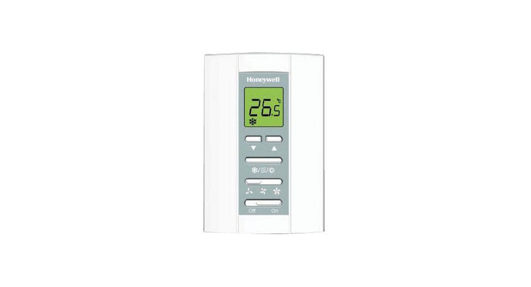
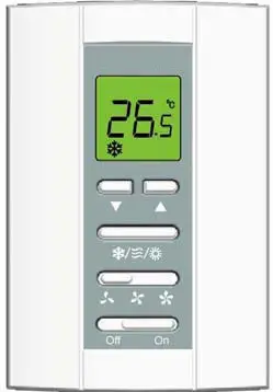
The T6812 digital thermostat is designed to control the valve and fan within 2-pipe fan-coil systems.Modern, attractive styling and comprehensive feature set make the T6812 suitable for a wide range of applications.There are 3 standard application configurations supported, and these are:
|
Application |
Description |
| 0 | 2 pipe system, heating only |
| 1 | 2 pipe system, cooling only |
| 2 | 2 pipe system, 1 stage heat or 1 stage cool, manual changeover |
The different applications can be selected from the installer setup mode and by altering the external wiring connections
FEATURES
- Clear and easy to read LCD display with backlight
- Room temperature or setpoint displayed
- The display can be configured to show ºC or ºF
- Heat / Cool or Fan-Only mode displayed on LCD
- Lockable keypad
- Room setpoint adjustable via simple-to-use up/down buttons
- Cool, Ventilation or Heat Icons display system function
- Manual control of fan speed (1, 2 or 3)
- Junction box or direct wall mounting
- Inbuilt temperature sensor
- Room temperature or setpoint displayed under normal operation (setpoint displayed during temperature adjustment)
- Proportional plus integral (P+I) control algorithm
- T6812 meets all relevant requirements for CE approval
- Installer setup mode allows operating parameters to be changed
- Installer set up settings retained in the event of a power loss
- -2°C to +2°C Temperature display offset via installer setup mode
- Setpoint stored in the event of power loss
- Easy to use installer setup mode allows for simple thermostat setup
- Setpoint range 10°C to 32°C
- Installer test mode for on-site wiring checks
- Line voltage (230V~) models are available
SPECIFICATIONS
| Setpoint range | 10…32ºC |
| Supply voltage | 230V~ (±10%) 50/60 Hz |
| Control Performance | P+I algorithm applied to ON/OFF control gives typical control to ±1.0°C at 22°C |
| Electrical ratings | Fan Motor: 230V~, 50…60Hz, 4.0A run, with inrush 10AValve Actuators: 230V~, 50…60Hz, 2.0A run, with inrush 3.5A |
| Operational life | Greater than 100,000 cycles (all loads) for thermostat contacts at 230V~ |
| Mounting | Mounts directly onto the wall or 86mm x 86mm or vertically mounted 2″ x 4″ wall-box. Mounting screws supplied. |
| Wiring | 7 screw-in terminals per unit, capable of accepting either 2 wires up to 1.5 mm2 |
| Enclosure | Plastic 2-piece housing |
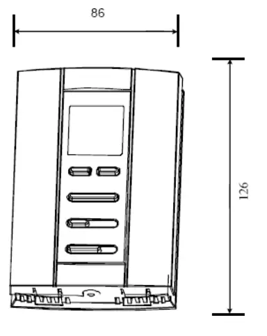
| Dimensions | 126 x 86 x 29 mm (h x w x d) |
| Environmental requirements | Operating temperature range 0ºC to +50ºC Shipping and storage temperature range -20 ºC to +55ºCHumidity range 5 to 95% RH, non-condensing |
| Approvals | CE mark. Complies with standards EN60730-1 (2001), EN55014-1 (2007), EN55014-2 (1997).The product must be wired as shown for CE compliance. |
T6812 APPLICATIONS
|
Application |
Description | Changeover | Fan speed |
Output type |
| 0 | 2 pipe system, heating only | No | Off/ 1,2 or 3 | On Off |
| 1 | 2 pipe system, cooling only | No | Off/ 1,2 or 3 | On Off |
| 2 | 2 pipe system, 1 stage heat or 1 stage cool | Manual | Off/ 1,2 or 3 | On Off |
INSTALLATION
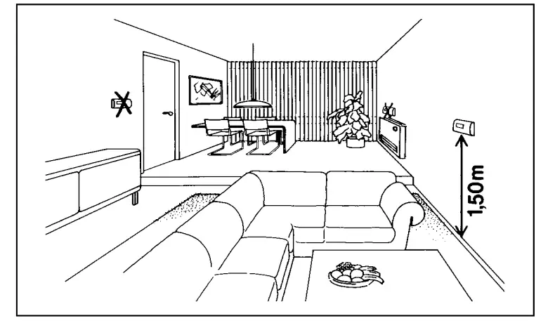 LocationThe T6812 thermostat is the temperature control element in the fan-coil or air-conditioning system and must be located about 1.2 to 1.5m above the floor (according to local building regulations) in a position with good air circulation at room temperature. Do not mount it where it could be affected by:-
- draughts or dead spots behind doors or in corners
- hot or cold air from ducts
- radiant heat from the sun or appliances
- unheated (uncooled) areas such as an outside wall behind the thermostat
- concealed pipes or chimneys
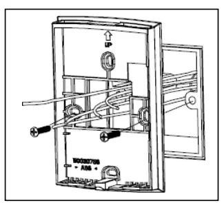
Mounting the thermostat
The T6812 thermostat can be directly mounted on the wall or on a vertically installed 2x4inch US junction box. Mounting screws are supplied for both alternatives.IMPORTANTThe installer must be a trained service engineerIsolate the power supply before beginning installation
- Locate the wall plate in the mounting position, insert the mounting screws through the appropriate holes, and screw them into position.
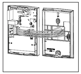
- Complete the wiring onto the terminal blocks in the main body of the thermostat.Attach the thermostat to the wall-plate as follows:
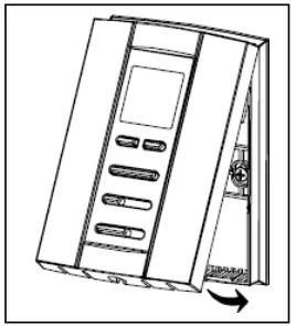
- Locate the 2 lugs at the top of the body onto the top of the wall plate and push the body onto the wall plate.
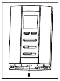
- Tighten the retaining screw in the lower edge of the thermostat.
Wiring the thermostat
The standard wiring access is via a hole in the center of the thermostat wall plate. See wiring diagrams for details.
Removing the thermostat from the wall
If it becomes necessary to remove the thermostat from the wall-plate:
- Isolate the power supply before removing the thermostat.
- Loosen the retaining screw in the lower edge of the thermostat.
- Pry the lower edge of the thermostat away from the wall plate.
- Use both hands to pull the thermostat straight away from the wall plate.
- NOTE – Incorrect removal of the thermostat from the wall plate may damage the device.
- Locate the wallplate and pull through the wires

- Complete the wiring onto the terminal blocks
- Locate lugs and clip the thermostat onto the backplate
- Tighten retaining screw at the base of the thermostat
INSTALLER SETUP MODE (ISU) – T6812 THERMOSTATS
|
ISU Number and description |
Range |
| 1 System Type | 0 = 2 Pipe system Heat Only |
| 1 = 2 Pipe system Cool Only | |
| 2 = 2 Pipe system 1H1C manual changeover (default) | |
| 9 Temperature Scale | 0 = ºF |
| 1 = ºC (default) | |
| 13 CPH value for HEATING | 1 – 12 (default = 4) |
| 14 CPH value for COOLING | 1 – 6 (default = 3) |
| 18 Temperature display offset | – 2.0ºC to + 2.0ºC incr. 0.5ºC (-4ºF to +4ºF incr. 1.0ºF) (default = 0º) |
| 19 Temperature display mode | 0 = Display room temperature (default) |
| 1 = Display setpoint | |
| 20 Heating range stops | 10 – 32ºC (default max. = 32ºC), 50 – 90ºF (default max. = 90ºF) |
| 21 Cooling range stops | 10 – 32ºC (default min. = 10ºC), 50 – 90ºF (default minx. = 50ºF) |
| 22 Keypad lockout | 0 = All keys available (default) |
| 1 = All keys locked |
DIMENSIONS
|
ORDERING SPECIFICATIONS |
|
| OS Number | Description |
| T6812A1000 | FCU Controller two pipe,230V~ |
WIRING DIAGRAMS
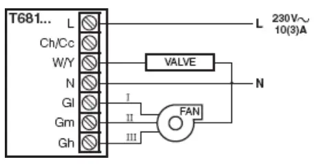
Typical wiring for two-pipe application with VC4 type valve –Spring return
 report this ad
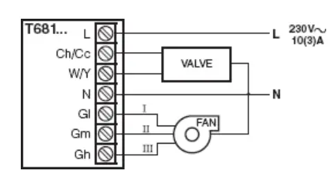
Typical wiring for two-pipe application with VC6 type valve –Driveopen / Drive closed
![]() Ademco 1 GmbHHardhofweg 4074821 MosbachPhone: +49 1801 466 388[email protected]homecomfort.resideo.com@2020 Resideo Technologies, Inc.All rights reserved The Honeywell Homea trademark is used under license from Honeywell International Inc. This product is manufactured by Resideo Technologies,Inc and its affiliates.
Ademco 1 GmbHHardhofweg 4074821 MosbachPhone: +49 1801 466 388[email protected]homecomfort.resideo.com@2020 Resideo Technologies, Inc.All rights reserved The Honeywell Homea trademark is used under license from Honeywell International Inc. This product is manufactured by Resideo Technologies,Inc and its affiliates.
![]() EN0H8581 R0 2020
EN0H8581 R0 2020
References
[xyz-ips snippet=”download-snippet”]