Honeywell TH9000 Series Equipment Interface Module Installation Guide
For up to 4 Heat/2 Cool systems with Equipment Interface Module or equivalent.
System Types
- Gas, oil, or electric heat with air conditioning
- Warm air, hot water, high efficiency furnaces, heat pumps, steam, gravity.
Must be installed by a trained, experienced technician
Read these instructions carefully. Failure to follow these instructions can damage the product or cause a hazardous condition.
![]() CAUTION: ELECTRICAL HAZARD. Can cause electrical shock or equipment damage. Disconnect power before beginning installation.
CAUTION: ELECTRICAL HAZARD. Can cause electrical shock or equipment damage. Disconnect power before beginning installation.
![]() MERCURY NOTICE: If this product is replacing a control that contains mercury in a sealed tube, do not place the old control in the trash. Contact your local waste management authority for instructions regarding recycling and proper disposal.
MERCURY NOTICE: If this product is replacing a control that contains mercury in a sealed tube, do not place the old control in the trash. Contact your local waste management authority for instructions regarding recycling and proper disposal.
Installation
- Remove cover from Equipment Interface Module (EIM).
- EIM can be mounted on equipment or on wall. Use included wall anchors for mounting onto drywall (drill 3/16″ holes for drywall; 7/32″ holes for plaster).
![]() CAUTION: This product may be damaged if mounted inside HVAC equipment. Install only on the outside of HVAC equipment.
CAUTION: This product may be damaged if mounted inside HVAC equipment. Install only on the outside of HVAC equipment.
Wiring
Connect wires as shown below (see wiring guides on following pages)

Restore power and check LED:
- LED blinks rapidly: Normal information transfer.
- LED blinks once: Incoming message to EIM.
- LED blinks continuously: Wiring problem.Check wiring to terminals 1, 2, 3.
- LED always off: Wiring problem. Check wiring to terminals 1, 2, 3.
- LED always on: EIM may need replacement
![]() NOTE: It is normal for the LED to blink continuously during startup, and while checking equipment status (Auto Discover mode).
NOTE: It is normal for the LED to blink continuously during startup, and while checking equipment status (Auto Discover mode).
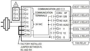
Wiring guide
- Typical hookup of conventional system with up to three-stage heat and two-stage cool with one transformer (3H/2C, 2H/2C, 2H/1C, 1H/2C, 1H/1C, 1H, 2H, 3H, 1C, 2C conventional).
 (WIRE TO TERMINALS ON THERMOSTAT)
 - Typical hookup of heat pump system with up to four-stage heat and two-stage cool with one transformer (4H/2C, 3H/2C, 2H/2C, 2H/1C, 1H/1C heat pump systems).
 (WIRE TO TERMINALS ON THERMOSTAT)
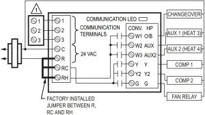
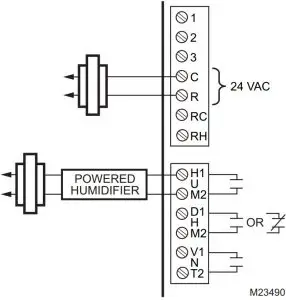
Wiring guide—equipment
With power supply
- Typical hookup of powered humidifier.
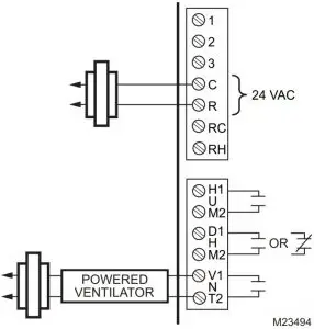
- Typical hookup of powered ventilation.
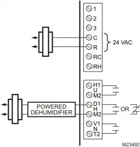
- Typical hookup of powered dehumidifier (whole house dehumidifier).
Without power supply
- Typical hookup of non-powered humidifier.
- Typical hookup of non-powered ventilation.
- Typical hookup of variable speed blower for dehumidification in low speed.


KEY
- NORMALLY OPEN, DRY CONTACTS
- NORMALLY CLOSED, DRY CONTACTS
Specifications
Temperature Ranges
- Heat: 40° to 90°F (4.5° to 32°C)
- Cool: 50° to 99°F (10° to 37°C)
Operating Ambient Temperature
- -30° to 150°F (-34 to 66°C)
Shipping Temperature
- -30° to 150°F (-34 to 66°C)
Operating Relative Humidity
- 5% to 90% (non-condensing)
Physical Dimensions
- 7-9/16″ H x 4-35/64″ W x 1-21/64″ D 185 mm H x 116 mm W x 34 mm D
Electrical Ratings
| Terminal | Voltage (50/60Hz) | Running Current |
| W Heating | 20-30 Vac | 0.02-1.0 A |
| W2 Heating | 20-30 Vac | 0.02-1.0 A |
| W3 Heating | 20-30 Vac | 0.02-1.0 A |
| Y Cooling | 20-30 Vac | 0.02-1.0 A |
| Y2 Cooling | 20-30 Vac | 0.02-1.0 A |
| Aux Auxiliary Heat | 20-30 Vac | 0.02-1.0 A |
| Aux2 Auxiliary Heat | 20-30 Vac | 0.02-1.0 A |
| G Fan | 20-30 Vac | 0.02-1.0 A |
| O/B Changeover | 20-30 Vac | 0.02-1.0 A |
[xyz-ips snippet=”download-snippet”]