Honeywell Thermostats Installation Guide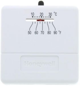
APPLICATION
The T812 and TS812 Thermostats are low voltage, controls for heat only, cool only or heating and cooling systems. See Table 1.
Table 1. Model Descriptions
| Model | Voltage | System | Anticipator |
| T812A | 24 Vac | Heat only | Adjustable 0.18A to 1.2A @ 30 Vac |
| T812B | 12 Vdc | Heat only | 0.18A to 1.2A @ 12 Vdc |
| T812C | 24 Vac | Heat and Cool | Adjustable 0.18A to 1.2A @ 30 Vac |
| T812D | 24 Vac | Cool only | Fixed 24 Vac to 30 Vac |
| TS812A | 750 mV | Heat only | 0.1A @ .75 Vdc |
![]() MERCURY NOTICEIf this control is replacing a control that contains mercury in a sealed tube, do not place your old control in the trash.
MERCURY NOTICEIf this control is replacing a control that contains mercury in a sealed tube, do not place your old control in the trash.
Contact your local waste management authority for instructions regarding recycling and the proper disposal of the old thermostat.
INSTALLATION
When Installing this Product…
- Read these instructions carefully. Failure to follow them could damage the product or cause a hazardous condition.
- Check the ratings given in the instructions and on the product to make sure the product is suitable for your application.
- Installer must be a trained, experienced service technician.
- After installation is complete, check out product operation as provided in these Instructions.
![]() CAUTION
CAUTION
- Electrical Shock Hazard.
- Can cause personal injury or equipment damage.
- Disconnect power supply before beginning installation.
Location
Locate the thermostat about 5 ft (1.5m) above the floor in an area with good air circulation at average temperature.
Do not mount the thermostat where it can be affected by:
- drafts, or dead spots behind doors and in corners.
- hot or cold air from ducts.
- radiant heat from the sun or appliances.
- concealed pipes and chimneys.
- unheated (uncooled) area such as outside wall behind the thermostat.
Fig. 1. Internal view of T812 with adjustable heat anticipator.
Wiring and Mounting
All wiring must comply with local codes and ordinances.
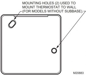 Fig. 2. Mounting hole locations for models without subbase.
T812 and TS812 Models Without Subbase
- In replacement applications, inspect the old wires for frayed or cracked insulation and replace any wires in poor condition; in new installations, run two wires to the location.
- Grasping the thermostat cover on the top and the bottom with one hand, push in on the bottom center and pull outward until the cover snaps free from the thermostat base.
- Connect the thermostat wires to the appropriate terminals on the thermostat back. See Fig. 4- for typical hookup diagrams.
- Push any excess wire back through the hole and plug any opening to prevent drafts that could affect thermostat performance.
- Adjust the heat anticipator (select models) to match the current draw of the system primary control. See Heat Anticipator Setting section.
- Fasten the thermostat to the wall with screws through the mounting holes on the upper left and right sides of the device. See Fig. 2.
- Replace the thermostat cover
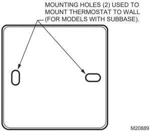 Fig. 3. Mounting hole locations for models with subbase.
T812 Models With Subbase
- In replacement applications, inspect the old wires for frayed or cracked insulation and replace any wires in poor condition; in new installations, run the appropriate number of wires to the location.
- Grasping thermostat cover on top and bottom with one hand, push in on bottom center and pull outward until cover snaps free from thermostat base.
- Disconnect thermostat from subbase by unscrewing the three screws under the thermostat cover. See Fig. 1.
- Connect the wires to the terminals on the front of the subbase. See Fig. 4-8.
- Push any excess wire back through the hole and plug any opening to prevent drafts that could affect thermostat performance.
- Loosely fasten thermostat subbase to the wall with a screw through the right mounting hole.Adjust the subbase so it is approximately level and start the second screw through the left mounting slot.
- Level the thermostat subbase for appearance only; it is not required for accurate operation.
- Tighten the mounting screws. See Fig. 3.
- Mount the thermostat to the thermostat subbase by tightening the three screws. See Fig. 1.
- Adjust the heat anticipator (select models) to match the current draw of the system primary control. See Heat Anticipator Setting section.
- Replace the thermostat cover.
 POWER SUPPLY. PROVIDE DISCONNECT MEANS AND OVERLOAD PROTECTION AS REQUIRED.
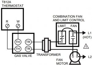 Fig. 4. T812A in typical gas heating system.
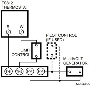 Fig. 5. Typical hookup to TS812A in millivolt system.
- POWER SUPPLY. PROVIDE DISCONNECT MEANS AND OVERLOAD PROTECTION AS REQUIRED
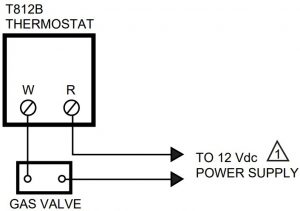 Fig. 6. T812B in 12 Vdc application.
- POWER SUPPLY. PROVIDE DISCONNECT MEANS AND OVERLOAD PROTECTION AS REQUIRED
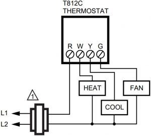 Fig. 7. T812C in heating and cooling system.
- POWER SUPPLY. PROVIDE DISCONNECT MEANS AND OVERLOAD PROTECTION AS REQUIRED.
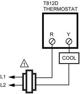 Fig. 8. T812D in cooling only application
SETTING AND CHECKOUT
Temperature Setting
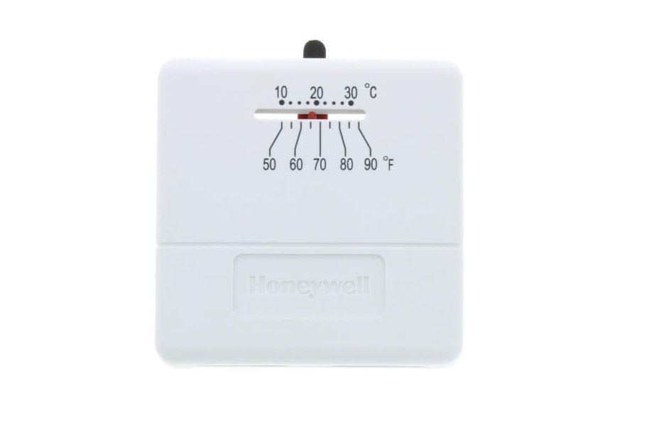
Move the temperature setting lever to the desired setpoint on the thermostat scaleplate, see Fig. 1, to control the temperature to desired point. (On positive off models, the control circuit is broken when the lever is moved to the extreme lowest setting of the temperature scale.)
Heat Anticipator Setting (Select Models)
IMPORTANT
- Use this thermostat only with controls that have current rating equal to (or within) the rating of the heat anticipator.
- Setting the heat anticipator allows the thermostat to maintain accurate temperature control.
Models with an adjustable heat anticipator should be adjusted to match the current draw of the primary control for optimum thermostat performance. To adjust, move the anticipator indicator lever to correspond to the control rating. See Fig. 1.
If the setting and current rating are not available, wire the thermostat into the system, but do not attach it to the wall. If the thermostat is already mounted, remove it from the wall, leaving it connected to the system wiring.
Connect an ammeter of the appropriate range (about 0.0A to 2.0A) between the terminals on the back of the thermostat. Move the temperature setting lever to a low setting so the contacts are broken. In cold weather, it may be necessary to hold the switch so the controls remain open. Allow the system to operate through the ammeter for one minute. Adjust the anticipator to match the meter reading.
NOTE: For best performance, the heat anticipator can require further adjustment. To lengthen burner-on time, move the indicator to a higher number, but not more than one-half scale marking at a time. To shorten burneron time, move the indicator in the opposite direction.
Cool Anticipator (Select Models)
Models with a cooling anticipator have a 24 Vac to 30 Vac fixed anticipator.
Checkout
![]() CAUTION
CAUTION
- Shorting Hazard.
- Can damage heat anticipator.
- Do not check operation by shorting across system control terminals.
Observe the system through at least one complete automatic cycle. Make certain that the system operates as intended. Check for correct operation of positive off switch, if used.
Calibration
This thermostat is carefully calibrated at the factory and cannot be field-adjusted.
Resideo Technologies, Inc.1985 Douglas Drive North, Golden Valley, MN 554221-800-468-150269-1606EFS—04 M.S. Rev. 02-20 | Printed in United States
© 2020 Resideo Technologies, Inc. All rights reserved.The Honeywell Home trademark is used under license from Honeywell International, Inc. This product is manufactured by Resideo Technologies, Inc. and its affiliates.
[xyz-ips snippet=”download-snippet”]