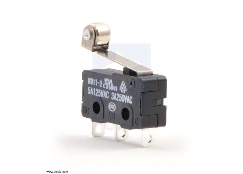
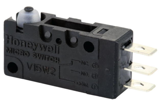
Honeywell V15W2 MICRO SWITCH
PERSONAL INJURY WARNING:DO NOT USE these products as safety or emergency stop devices or in any other application where failure of the product could result in personal injury.Failure to comply with these product installation instructions could result in death or serious injury.
CAUTION SWITCH DAMAGE:
- Wiring must be rated to meet or exceed circuitry requirements.
- Connecting circuitry must not exceed switch rating.
- Wiring connections must be properly secured.
- Do not exceed recommended soldering time or temperature.
- Do not contact switch housing with soldering device.
- Do not exceed recommended mounting screw tightening torques.
- Discontinue use if switch has been damaged or cover removed.
- Do not apply side loads to actuator or exceed specified travel limits.
- Do not operate or store in areas where corrosive gases such as hydrogen sulfide are present.
Failure to comply with these product installation instructions could result in death or serious injury.
GENERAL INFORMATION
MICRO SWITCH V15W2 basic switches are precision snap-action contact mechanisms enclosed in plastic cases. Switch actuation triggers the mechanical closure of the switch’s contacts. The switches are approved for use in Zone 2 hazardous locations. While a small amount of arcing occurs between the switch contacts during contact closure, the switch is environmentally sealed so that flammable gases cannot enter into the switching cavity. This mimimizes the chances of ignition of flammable gases in a hazardous atmosphere. The IEC Ex approvals are as such:
Ex nC IIA T5 Gc for an ambient temperature range of -25°C to +85°C per IEC 60079-0 6th Edition (2011) and IEC 60079-15 4th Edition (2010) via certificate IEC Ex DEK 17.0053U.The ATEX approval are as such: II 3 G Ex nC IIA T5 Gc per EN 60079-0 : 2012 + A11 : 2013 and EN 60079-15 : 2010 via ATEX certificate DEKRA 19ATEX0013 U
Mounting Information
| Mounting hole size | Screw type* | Screw size | Tightening Torque (max.) |
|
3,1 mm |
Flat fillister head |
3 mm |
4,5 kg-cm
[3.9 in-lb] |
| 2,9 mm
(-K option) |
Flat fillister head |
#4 |
4,5 kg-cm
[3.9 in-lb] |
*To prevent loosening of screws, use spring washers under screw heads and thread lock adhesive.
- Turn OFF the power supply before mounting or removing the switch, wiring, or performing maintenance or inspection. Failure to do so may result in electric shock.
- Switch must be mounted in an enclosure to prevent contact to live electrical parts and to protect the switch from exposure to ultraviolet light.
- Mount the switch onto a flat surface. Mounting on an uneven surface may cause deformation of the switch, resulting in faulty operation or damage.
- Use an operating device with low frictional resistance and of a shape that will not interfere with the plunger seal, otherwise the plunger may be damaged or the sealing may deteriorate.
- Position the operating device perpendicular to the actuator/pushbutton to prevent side loading of the switch actuator or pushbutton.
- Position the operating device so that no force is applied to the pushbutton/actuator when the switch is in the free position.
- The operating device should be positioned so that when the switch is in the operating position it should move the actuator no less than 70 % of the total travel. Setting the travel position so that less than 70 % of the total travel is used may cause poor contact or welding conditions due to an insufficient contact switching force.
- The operating device should never force the actuator/pushbutton to exceed the total travel position.
WIRING INFORMATION
- Connect wires firmly to terminals.
- Replace wires that have damaged insulation.
- Use properly sized receptacles.
- Use wire rated for the application’s electrical load and application’s temperature.
- Provide strain relief when a potential exists for forces to be transferred from the lead wires to the switch terminals.
MICRO SWITCH V15W2 Basic Switch
MOUNTING AND CIRCUIT INFORMATIONMounting dimensions shown below.A circuit diagram is included on the switch case labeling each of the terminals. The normal position corresponds to the switch plunger in its released position.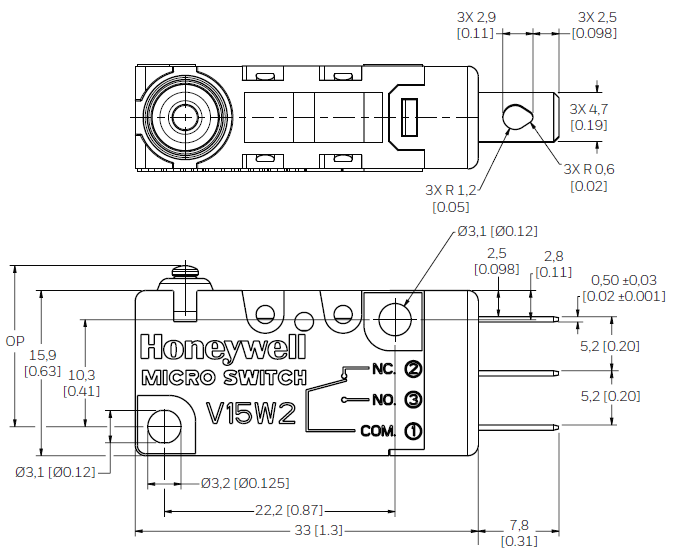
SOLDERING GUIDELINES
When hand soldering the switch’s terminals, do not exceed five seconds at 350 °C [662 °F]. Contacting the switch housing with the soldering device may damage the switch housing. Solder joints must not be moved for at least one minute after soldering.Do not try to clean the switch with a solvent or similar substance after the soldering process
SPECIFICATIONS
| Electrical rating | 5 A (resistive), 125 Vac/250 Vac |
| Operating temperature range | -25 °C to 85 °C
[-13 °F to 185 °F] |
| Rate of actuation | 0,1 mm/s to 1000 mm/s |
| Operating frequency (electrical) | 25 operations/minute max. |
| Operating frequency (mechanical) | 60 operations/minute max. |
SCHEDULE OF LIMITATIONS
The voltage, current, mechanical mounting, connections, creepage, and clearance distance specifications must be as per the instruction manual.The switch body shall be installed using a protective cover providing resistance to impact according EN/IEC 60079-0 clause 26.4.2 table 13 (after thermal endurance tests according to clause 26.7 for relevant non-metallic cover) for equipment grouping II and classification high risk for mechanical danger for protective covers.The electrical termination of the device installed in the application shall have a suitable enclosure providing a degree of protection of at least IP54 according to EN/IEC 60079-15 clause 6.3. Creepage distances and clearance specifications at the terminals must be taken into account when making electrical connections. Reference table 2 of EN/IEC 60079-15.
WARRANTY/REMEDY
Honeywell warrants goods of its manufacture as being free of defective materials and faulty workmanship during the applicable warranty period. Honeywell’s standard product warranty applies unless agreed to otherwise by Honeywell in writing; please refer to your order acknowledgment or consult your local sales office for specific warranty details. If war-ranted goods are returned to Honeywell during the period of coverage, Honeywell will repair or replace, at its option, without charge those items that Honeywell, in its sole discretion, finds defective. The foregoing is buyer’s sole remedy and is in lieu of all other warranties, expressed or implied, including those of merchantability and fitness for a particular purpose. In no event shall Honeywell be liable for consequential, special, or indirect damages.
While Honeywell may provide application assistance person-ally, through our literature and the Honeywell web site, it is buyer’s sole responsibility to determine the suitability of the product in the application.Specifications may change without notice. The information we supply is believed to be accurate and reliable as of this writing. However, Honeywell assumes no responsibility for its use.Honeywell Advanced Sensing Technologies services its customers through a worldwide network of sales offices and distributors. For application assistance, current specifications, pricing or the nearest Authorized Distributor, visit sps.honeywell.com/ast or call:
 Honeywell Advanced Sensing Technologies 830 East Arapaho RoadRichardson, TX 75081sps.honeywell.com/ast
References
[xyz-ips snippet=”download-snippet”]