
![]()
VB6 SERIES 6-WAY CONTROL BALL VALVES AND ACTUATORSINSTALLATION INSTRUCTIONS
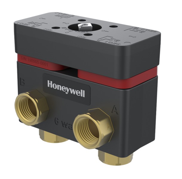
ApplicationThe VB6 6-Way Control Ball Valves regulates hot and chilled water with glycol solutions up to 60% in heating, ventilating, and air conditioning (HVAC) systems. These valves ship with a direct-coupled actuator factory-installed for modulating control. The valve is designed to be used exclusively with the MN7510A2001 actuator.Application Notes![]() IMPORTANT: Valve sizing is important for correct system operation. Undersized valves do not have sufficient capacity at maximum load. Oversized valves do not have sufficient authority over the load in modulating applications. Oversized valves can cause excessive cycling and the seat and ball can be damaged because of the restricted opening.Proper UseThese valves are intended for use in chilled water and hot water closed-loop applications only, with a media temperature range of 0 ºF to +212 ºF (18 ºC to 100 ºC), and static pressures up to 600 psi.
IMPORTANT: Valve sizing is important for correct system operation. Undersized valves do not have sufficient capacity at maximum load. Oversized valves do not have sufficient authority over the load in modulating applications. Oversized valves can cause excessive cycling and the seat and ball can be damaged because of the restricted opening.Proper UseThese valves are intended for use in chilled water and hot water closed-loop applications only, with a media temperature range of 0 ºF to +212 ºF (18 ºC to 100 ºC), and static pressures up to 600 psi.
These valves are to be operated with the Honeywell MN7510A2001 actuator only. Water should be properly filtered, treated, and conditioned for good operating performance, according to local conditions, and recommendations of the boiler or chiller manufacturers. The installation of strainers and filters is recommended.![]() IMPORTANT: The presence of excessive iron oxide (red rust) in the system voids the valve warranty.Required Operating TorqueThe VB6 series 6-way control ball valves are to be operated with the Honeywell MN7510A2001 actuator only These valves use a patented seat design that reduces the torque needed. The nominal required operating torque is 88 lb-in.Table 1. Close off Pressure
IMPORTANT: The presence of excessive iron oxide (red rust) in the system voids the valve warranty.Required Operating TorqueThe VB6 series 6-way control ball valves are to be operated with the Honeywell MN7510A2001 actuator only These valves use a patented seat design that reduces the torque needed. The nominal required operating torque is 88 lb-in.Table 1. Close off Pressure
| Valve Size | Close off Pressure |
| 1/2 inch and 3/4 inch | 200 psi (1380 kPa) |
Flow Characteristic
The VB6 series 6-way Ball Valves have true equal percentage flow characteristics, thanks to precision-machined metal discs in front of the ball.

® U.S. Registered Trademark Copyright © 2021 Honeywell Inc.All Rights ReservedPrinted in USA31-00380M-02Valve SizingTypical pressure drop across a control valve is in the range of 3 to 5 psi, however, the best control is achieved when the valve pressure drop is as close to the coil pressure drop as possible. The 6-Way valve will have two CV calculations, one each for Sequence 1 and Sequence 2, which will feature different flow rates most of the time.
INSTALLATION
When installing this product…
- Read these instructions carefully. Failure to follow them could damage the product or cause a hazardous condition.
- Check ratings given in instructions and on the product to ensure the product is suitable for your application.
- The installer must be a trained, experienced service technician.
- After installation is complete, check out product operation as provided in these instructions.
Preparation
 Caution: Equipment Damage HazardForeign particles like dirt and metal chips can damage the ball seals. For trouble-free operation of the product, good installation practice must include initial system flushing and chemical water treatment. Clean the lines upstream of particles larger than 1/16 inch diameter (welding slag, pipe scale, sand and other suspended particulate). Use of a 50 micron (or finer) system side stream filter is suggested. Remove all filters before flushing. Do not use boiler additives, solder flux and wetted materials which are petroleum-based or contain mineral oil, hydrocarbons, or ethylene glycol acetate. Compounds that can be used, with a minimum 40% water dilution, are diethylene glycol, ethylene glycol, and propylene glycol (antifreeze solutions). If installing these valves in an addition to, or retrofitting an existing building, do not assume that the fluid in the existing piping meets these criteria.CALIFORNIA PROPOSITION 65 WARNING
 This product can expose you to chemicals including lead, which is known to the State of California to cause cancer, birth defects, or other reproductive harm. For more information, go to www.P65Warnings.ca.gov.
Mechanical Installation of the Valve
![]() IMPORTANT: Hold valve with pipe wrench by hexagonal fitting ONLY. Do NOT handle the Valve body with the pipe wrench; product damage may result.Refer Dimension section on page 9 for more details on the dimensions of the Valve body and actuator.
IMPORTANT: Hold valve with pipe wrench by hexagonal fitting ONLY. Do NOT handle the Valve body with the pipe wrench; product damage may result.Refer Dimension section on page 9 for more details on the dimensions of the Valve body and actuator.
- Clean the lines upstream of particles larger than 1/16 in. diameter (welding slag, pipe scale, and other contaminants) to properly flush the system.
- Proceed with installation once the system specifics (expansion/contraction of the system and its medium as well as operating pressures) are within tolerances.
- Eliminate air or air bubbles from the system.
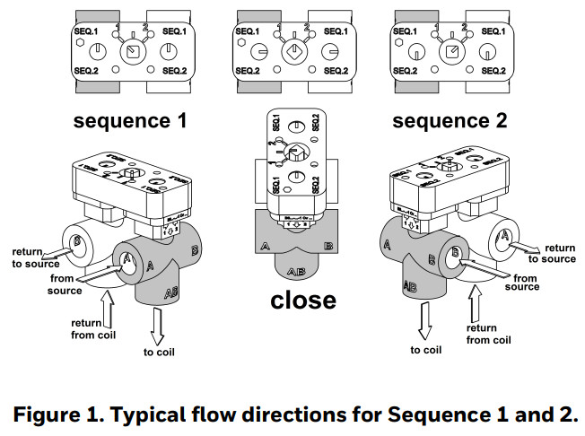
- Use the markings on the valve bodies to familiarize yourself with the A, B, and AB piping connections.
- Connect the AB-ports of the valve to the supply and return pipes of the coil.
- Connect the A-ports and B-ports as per the flow sequences. Refer to the below figure.
 IMPORTANT: Strictly follow flow direction and port connections as per flow sequences.
 - Clear threads on both valve and piping of any debris. Honeywell recommends Permabond A1044 or equivalent thread or pipe sealant. While using Teflon tape, it is recommended to use 4-6 rounds of tape applied tightly in a clockwise rotation. When using hemp as pipe sealant, ensure no strands are left in the valve or piping.
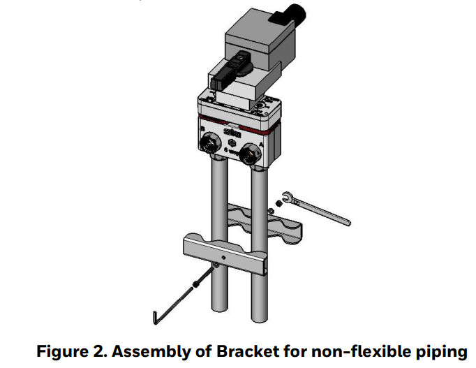
- Valves must be installed to avoid unnecessary pull or twist in the valve housing.
- Use the Bracket as shown below figure if nonflexible pipes are used in piping to keep pipes firm and parallel.
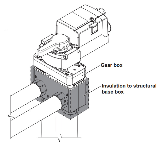
Valve Insulation
To avoid water condensation dripping from the 6way valve, insulate around the pipe connections and the structural box, but do not cover the gearbox in insulation.
Mechanical Installation for Actuator
Caution: To avoid personal injury (electrical shock) and to prevent equipment damage, before installation, you must remove power.
Mounting Position
- Choose a mounting position permitting easy access to cables and controls.
- Make sure that the actuator stem is in horizontal to upright vertical position, but never in a below horizontal position. Condensate from the Valve body may flow into the Gearbox or actuator, causing damage.
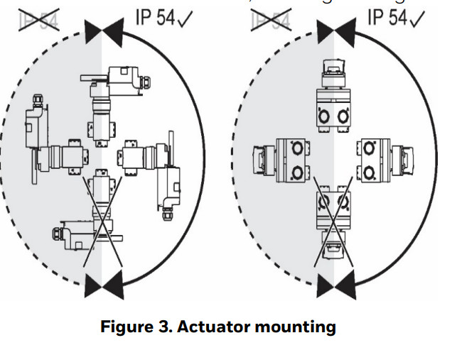
![]() NOTE:Further, in order to guarantee IP54, only original Honeywell grommets may be used. Preparing Actuator for mounting
NOTE:Further, in order to guarantee IP54, only original Honeywell grommets may be used. Preparing Actuator for mounting
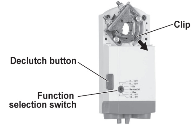
- Use a suitable plier to hold the clip of the Universal shaft adapter.
- Pull out the Clip as shown in the below figure to remove the Universal shaft adapter. Now, the actuator is ready to assemble on a 6-way control ball valve.
Assembling the actuator on the Valve body
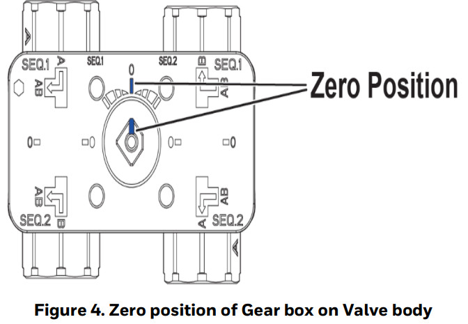
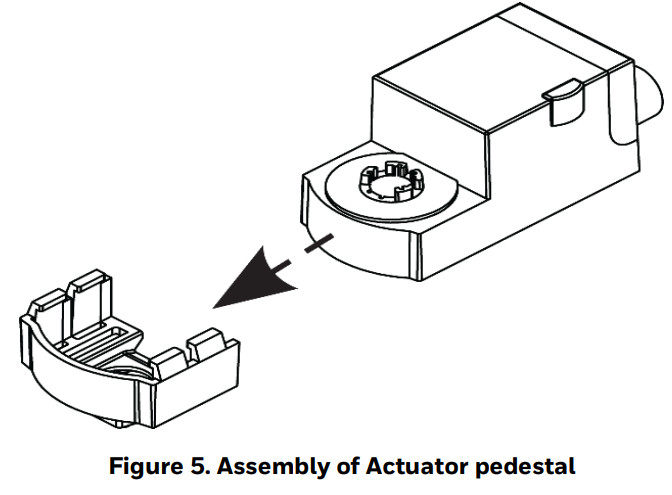
- Make sure that the Gearbox is in zero position as shown the below figure. Use the appropriate wrench to adjust (if necessary).
- Slide the actuator into the Actuator pedestal as shown in the below figure. Do not use additional tools or pressure as the Actuator pedestal is designed to press-fit with the MN7510A2001 actuator.
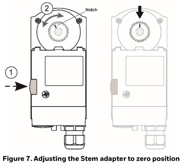
- Insert the Stem adapter into the Actuator output hub (Stem adapter and Output hub are keyed so they can be assembled in one way only). IMPORTANT:To prevent equipment damage, you must remove power or set the function selection switch to the “Service/Off” position before manual adjustment.
- Press and hold the Declutch button to permit rotation of the Stem adapter to any position. Rotate the Stem adapter, so that the notch on the Stem adapter points as shown in figure below.
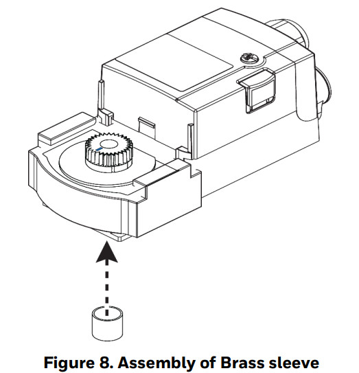
- Slide the Brass sleeve over the end of the stem adapter as shown in the figure below.
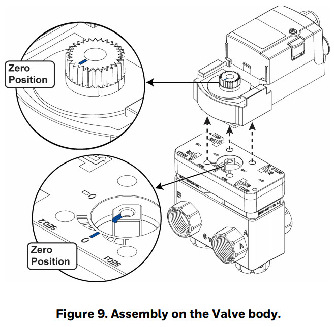
- Place the actuator assembly on the Valvebody as shown below figure. IMPORTANT:The only possible way that the valve stem and actuator Stem adapter can be assembled together is with both in the Zero position.
- Insert the Screw (M4) and Washer (supplied with the package) into the linkage shaft and tighten the screw (1.8 -2.5 Nm) to firmly assemble the actuator with the Valve body. See figure below.
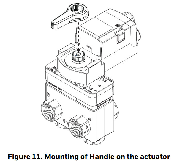
- Hold the handle in the vertical position (as shown below) and insert the handle on the linkage Stem adapter knob by pressing it downwards (press fit) to assemble it firmly.


Manual Adjustment
![]() IMPORTANT:To prevent equipment damage, you must remove power or set the function selection switch to the “Service/Off” position before manual adjustment.After removing power or setting the function selection switch to the “Service/Off” position, the Gearbox can be disengaged using the Declutch button, permitting the handle to be manually rotated to any position.
IMPORTANT:To prevent equipment damage, you must remove power or set the function selection switch to the “Service/Off” position before manual adjustment.After removing power or setting the function selection switch to the “Service/Off” position, the Gearbox can be disengaged using the Declutch button, permitting the handle to be manually rotated to any position.
Electrical Installation
The most important part of the electrical installation is the power supply for the actuator.Caution: To avoid personal injury (electrical shock) and to prevent equipment damage, before installation, you must remove power.
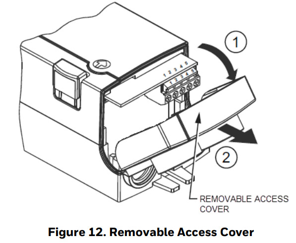
- Unscrew the actuator wiring cover in order to access to the terminal block(s) as shown below.
- Perform the wiring of the actuator using Figure 13 to Figure 15 as per the required application.
- If necessary, use the appropriate electrical cable conduits and cable gland to properly secure the actuator wiring.
- Replace the wiring cover once done.

Actuator Run modes
The function selection switch (see Figure 16) can be used to place the actuator into any one of two different modes:
- Modulating run mode
- Floating/2-position run mode
- Service/Off mode.
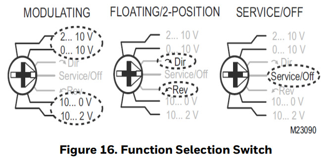
Modulating Run Mode
The Modulating Run mode can be used in four different types of control settings:
- 2…10 Vdc
- 0…10 Vdc
- 10…0 Vdc
- 10…2 Vdc
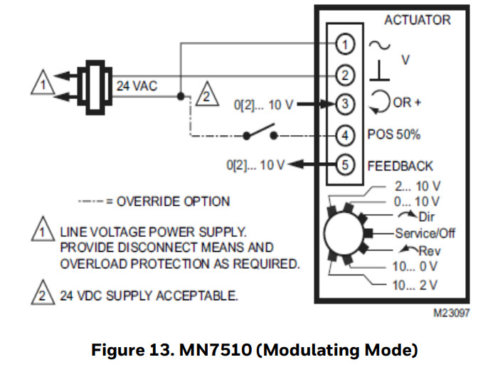
If the function selection switch has been set to one of the four modulating control settings – and if the actuator is wired correspondingly (see Figure 13) – then as soon as operating power is applied, the shaft adapter will run first completely counterclockwise and then completely clockwise, after which it will run according to the control signals applied.
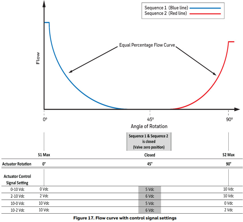
Use the above flow curve with given actuator control signal settings to configure 6-way valve for Sequence 1 (cooling), Sequence (2), and Off-position. Note that in Figure 13 it is shown how to override the actuator with a switch on wiring terminal 4 to go to the 50% position. This may also be used to rotate the valve to the zero (closed) position.
![]() IMPORTANT:The zero (closed) position of the valve can be achieved with the control signal as shown in the below table.
IMPORTANT:The zero (closed) position of the valve can be achieved with the control signal as shown in the below table.
| Valve closed command (45 degree actuator rotation) | |
| Actuator Control Signal Setting | Controller Output |
| 0-10 Vdc | 5Vdc |
| 2-10 Vdc | 6 Vdc |
| 10-0 Vdc | 5Vdc |
| 10-2 Vdc | 6 Vdc |
Floating/2-Position Run Mode (Not recommended)
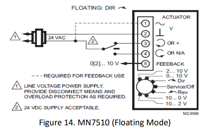
Using the MN7510A2001 actuator in floating / 2-position mode is not recommended with 6-way valves. Both Sequence 1 and Sequence 2 are closed at the actuator mid-stroke, 45-degree actuator rotation. It must be possible to command the actuator to position itself in the midstroke position, which is difficult to do with precision in floating mode, and impossible when floating mode is used for 2-position control. If it is desired to use the 6-way valve for simple seasonal changeover service, it is best if three distinct positions can be achieved:
1. Fully clockwise actuator rotation for Sequence 2 to be fully open.2. Fully counterclockwise actuator rotation for Sequence 1 to be fully open.3. Exactly mid-stroke, 45-degree actuator rotation, for Sequence 1 and 2 both being closed.
This scheme can only be achieved with the actuator selector switch set to one of the four modulating modes, using 0-10 Vdc, 2-10 Vdc, 10-0 Vdc, or 10-2 Vdc to achieve full clockwise, full counterclockwise, and precisely mid-stroke actuator positions.If desired, the actuator analog feedback can be used to verify the actual position. If only step 1 and 2 above are desired, and there is no need for step 3 to rotate the actuator to exactly 45 degrees to turn both Sequences 1 and 2 completely off, the floating mode may be used for 3-wire 2-position control.
Power-Off BehaviorIf power is removed, the shaft adapter remains in position.Service/Off ModeIf the function selection switch is set to the “Service/Off” position, then all rotary movement is canceled, and all control signals are ignored, allowing the actuator to be manually operated safely. Press and hold the De-clutch button and use the handle to operate the actuator to Sequence 1, 2, or, Off positions.Overriding The MN7510A2001 can be overridden to the 50% position by applying a 24 V signal to terminal 4 (see Figure 13.) With 24 V signal applied the actuator will ignore the control signal at terminal 3 and instead drive to the 50% position closing both Sequence 1 and Sequence 2.Feedback If correspondingly wired via terminal 5 (see Figure 13 to Figure 15), the actuator provides a feedback signal proportional to the actual position of the shaft adapter.
Flow Rate as per Valve Pressure Difference (ΔP)
Table 3. Flow rate as per Valve Pressure difference
| Valve Size | CV Value | Flow Rate (in g pm) for below Valve ΔP (in psid) | |||||||||||
| (inch) | For Sequence for 2• | 0.50 | 0.75 | 1.00 | 2.00 | 3.00 | 4.00 | 5.00 | 6.00 | 7.00 | 8.00 | 9.00 | 10.00 |
| 1/2 inch | Cv 0.30 | 0.21 | 0.26 | 0.30 | 0.42 | 0.52 | 0.60 | 0.67 | 0.73 | 0.79 | 0.85 | 90 | 0.95 |
| Cv 0.46 | 0.33 | 0.40 | 46 | 0.65 | 0.80 | 92 | 1. | 1. | 1. | 1.30 | 1. | 1. | |
| Cv 0.80 | 0.57 | 0.69 | 0.80 | 1. | 1. | 1.60 | 2. | 2. | 2. | 2. | 2.40 | 3. | |
| Cv1.20 | 0.85 | 1. | 1.20 | 1.70 | 2. | 2.40 | 3. | 3. | 3. | 3. | 3.60 | 4. | |
| Cv 1.90 | 1. | 2. | 1.90 | 3. | 3. | 3.80 | 4. | 5. | 5. | 5. | 5.70 | 6. | |
| Cv 3.00 | 2. | 2.60 | 3.00 | 424 | 5.20 | 600 | 7. | 7. | 8. | 8. | 9.00 | 9. | |
| Cv 4.70 | 3. | 4. | 4.70 | 7. | 8. | 9.40 | 11. | 12. | 12. | 13. | 14.10 | 15. | |
| Cv 7.40 | 5. | 6. | 7.40 | 10. | 13. | 14.80 | 17. | 18. | 20. | 21. | 22.20 | 23.40 | |
| 3/4 inch | Cv 4.70 | 332 | 4. | 4.70 | 7. | 8. | 9.40 | 11. | 12. | 12. | 13. | 14.10 | 15. |
| Cv 7.40 | 5. | 6. | 7.40 | 10. | 13. | 14.80 | 17. | 18. | 20. | 21. | 22.20 | 23.40 | |
| Cv 10.00 | 7. | 9. | 10.00 | 14. | 17. | 20.00 | 22. | 24. | 26. | 28. | 30.00 | 32. | |
| Cv 14.00 | 9.90 | 12. | 14.00 | 19.80 | 24. | 28.00 | 31.30 | 34. | 37. | 39.60 | 42.00 | 44. |
*For fully open valve position.For example:The VB6A003+012+AL valve is with CV 0.30 (for sequence 1) and CV is 1.20 (for sequence 2).If we consider the valve pressure difference (ΔP) 4 psid then as per the above table, the Flow rate for sequence 1 will be 0.60 gpm and for sequence 2 will be 2.40 GPM.
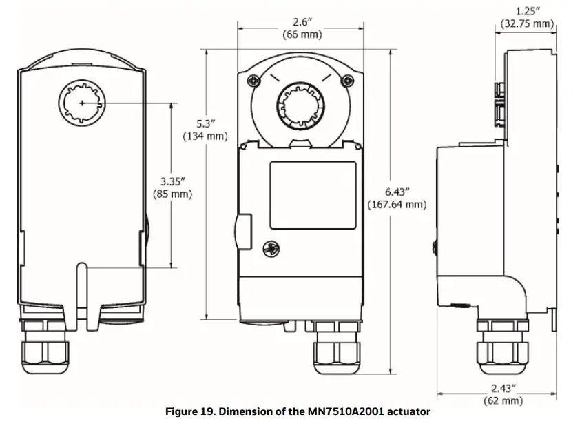
DIMENSIONS
Dimension of Valve body
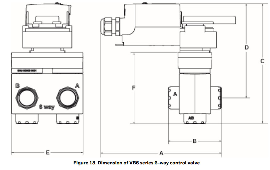
Table 2. Dimensions
| Valve nominal size | A | B | C | D | E | F | |
| Valve Body | Inch | inch (mm) | inch (mm) | inch (mm) | inch (mm) | inch (mm) | inch (mm) |
| 1/2′ | 6.85(174) | 2.76 (70) | 6.63 (168) | 5.33 (135) | 4.14 (105) | 3.77 (95) | |
| 3/4′ | 7.01 (178) | 3.07 (78) | 6.92 (176) | 5.46 (139) | 4 15 (105) | 4.09 (104) | |
Dimension of Valve body
The material in this document is for information purposes only. The content and the product described are subject to change without notice. Honeywell makes no representations or warranties with respect to this document. In no event shall Honeywell be liable for technical or editorial omissions or mistakes in this document, nor shall it be liable for any damages, direct or incidental, arising out of or related to the use of this document. No part of this document may be reproduced in any form or by any means without prior written permission from Honeywell.
![]() Honeywell Building Technologies715 Peachtree Street NEAtlanta, GA 30308The United States of America.https://buildings.honeywell.com
Honeywell Building Technologies715 Peachtree Street NEAtlanta, GA 30308The United States of America.https://buildings.honeywell.com
® U.S. Registered Trademark©2021 Honeywell International Inc.31-00380M-02 I Rev. 06-21
References
[xyz-ips snippet=”download-snippet”]