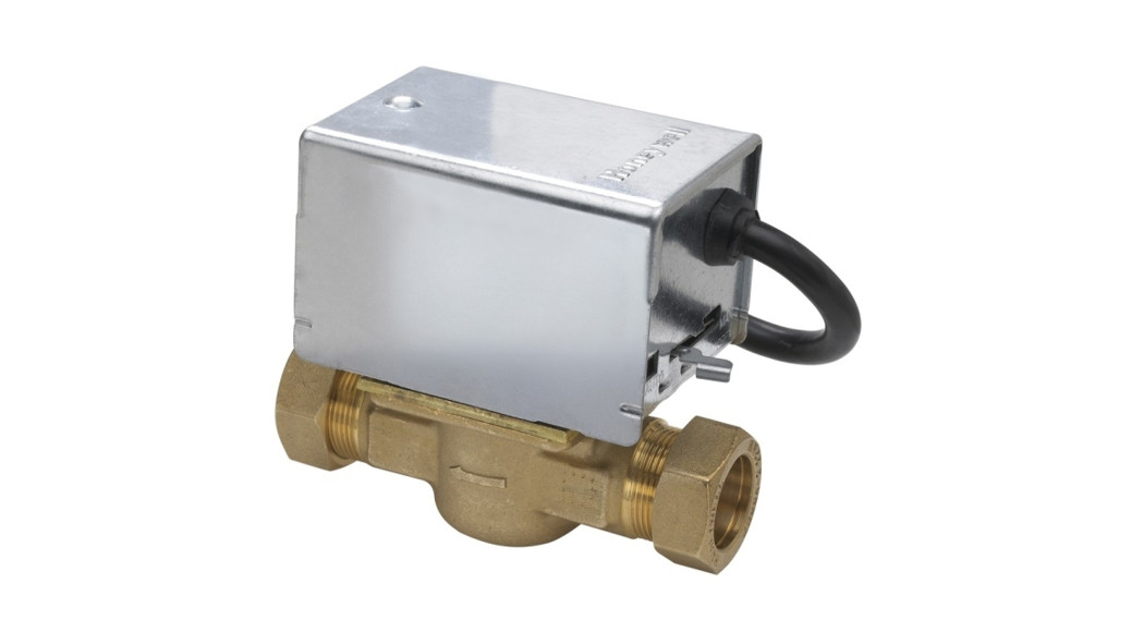
 VU4143HMotorized Zone Valves
This is a legacy product document supported by Resideo. It is no longer manufactured

APPLICATION
These two-position (open/closed) motorized zone valves are for use in small bore and mini-bore central heating installations to provide ”zoned’ space temperature control. Depending upon application they can be controlled by a room thermostat or by an aquastat.
SPECIFICATIONS
The specifications following are nominal and conform to generally accepted industry standards. Honeywell is not responsible for damages resulting from misapplication or misuse of its products.
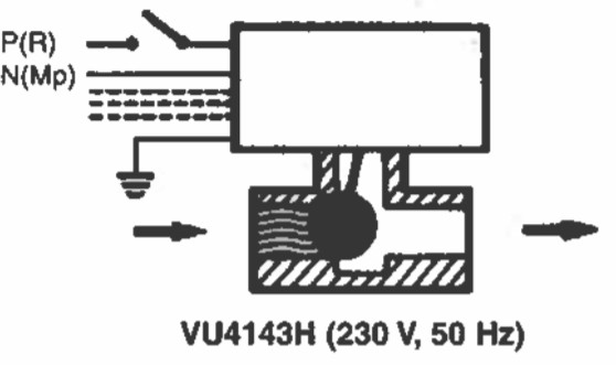
| Electrical Rating: | 230 Vac 50Hz, 0.03A | |
| Maximum differential pressure for close-off, and flow capacity rating: | ||
| 1/2” | 1.35 bar (135 kPa), | 3.0 kvs |
| 3/4” | 0.69 bar (69 kPa), | 0.69 kvs |
| 1” | 0.69 bar (69 kPa), | 6.9 kvs |
| Maximum static pressure: | 20 bar | |
| Maximum ambient temperature: | 50°C | |
| Maximum flow temperature: | 88°C | |
| Minimum flow temperature: | 5°C (not condensing air) (Special models available for chilled water applications.) | |
| Auxiliary switch rating: | 10A (2.2A) at 220/240 Vac, 50Hz. | |
| Approved: | CE |
MODELS:
|
MOUNTING
|
INSTALLATION
|
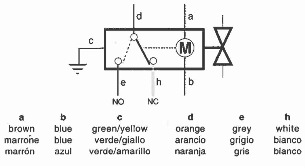
WIRING DIAGRAMS
|


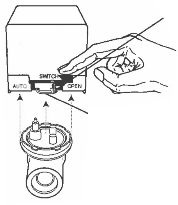
OPERATION
Caution: Disconnect power supply before connecting wiring to prevent electrical shock or equipment damage.The actuator has three different manual settings: AUTO, OPEN, and SWITCH.In AUTO mode, the valve cycles with the thermostat and activates the auxiliary switch valve is at lull open.In OPEN mode, the valve is opened to allow the system to be filled, flushed, or drained. The auxiliary switch is not activated. The valve returns to AUTO mode when it is energized.In SWITCH mode, the valve is opened and the auxiliary switch is activated to run the pump. The valve returns to AUTO mode when it is energized.
REMOVING THE ACTUATOR:
Note: It is not necessary to drain the system if the valve body assembly remains in the pipeline.
- Turn power supply OFF. Disconnect electrical leads, carefully noting the position and color of each lead.
- Place the manual operating lever in the OPEN position
- Remove actuator by depressing locking button and lifting straight up
MOUNTING THE ACTUATOR:
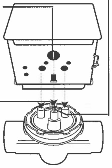
- Notch
- Actuator Coupling
- Ensure shaft slot polo% towards notch on side of the body for fitting into the engaging shaft
Home & Building Control ProductsPrinted in Canada
[xyz-ips snippet=”download-snippet”]