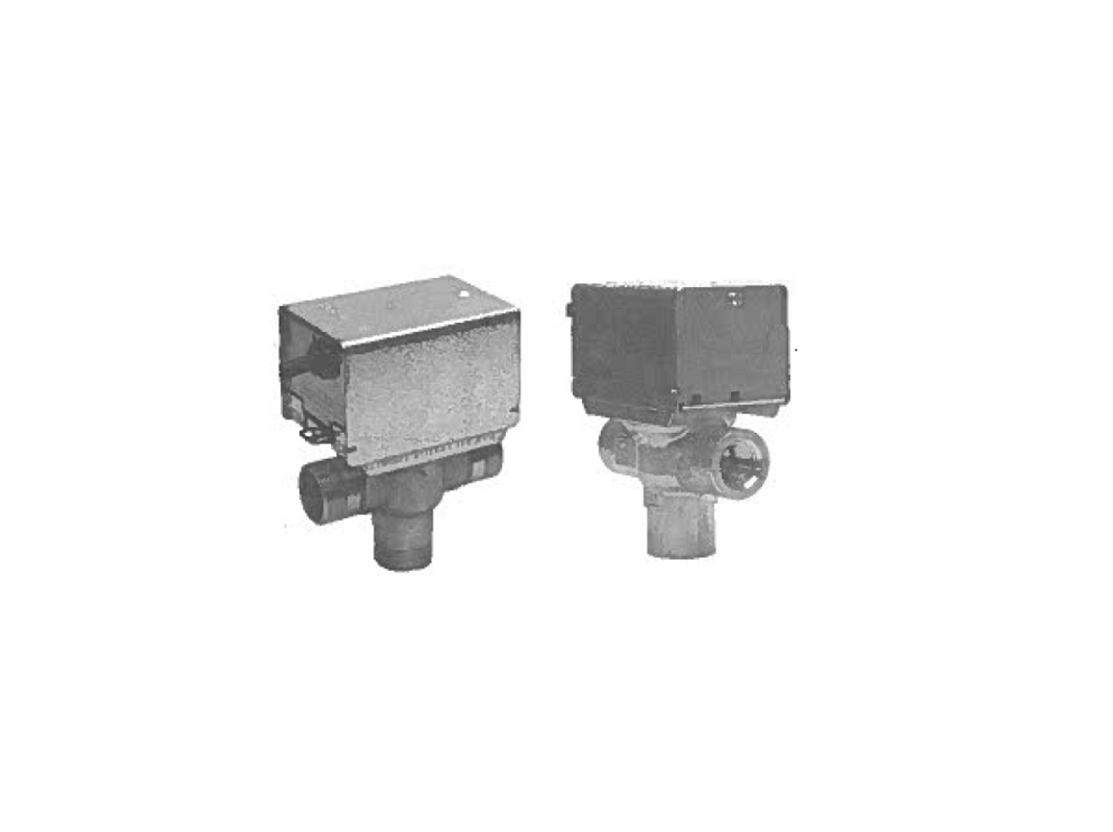
Honeywell VU4144C Motorized Diverter Valves Installation Guide
APPLICATION
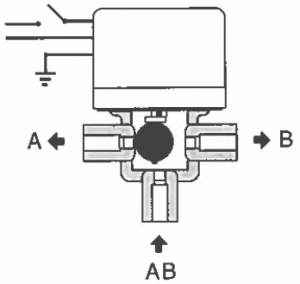
These 3-way motorized diverting valves provide two-position control of supply water flow in hydronic central heating installations and domestic hot water systems. Depending upon application they can be controlled by a room thermostat or by an aquastat (boiler thermostat).
SPECIFICATION
The specifications following are nominal and conform to generally accepted industry standards. Honeywell is not responsible for damages resulting from misapplication or misuse of its products.
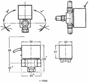
Electrical Rating: 230 Vac 50Hz, 0.04AMaximum differential pressure for close-off, and flow capacity rating: 3/4″ 0.69 bar (69 kPa), 6.0 kvs 1″ 0.55 bar (55 kPa), 8.1 kvsMaximum static pressure: 20 barMaximum ambient temperature: 50°CMaximum flow temperature: 88°CMinimum flow temperature: 5°C (not condensing air) (Special models required for chilled water application)Approved: CE
MOUNTING
INSTALLATION:
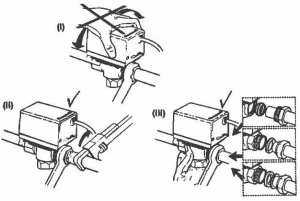
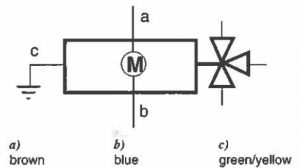
WIRING DIAGRAMS:
Caution: Disconnect power supply before connecting wiring to prevent electrical shock or equipment damage.
OPERATION
Disconnect power supply before using the OPEN position.The actuator has two manual settings: AUTO, OPEN.In AUTO mode, the valve cycles with the thermostat.In OPEN mode, the valve is opened to allow the system to be filled, Hushed or drained. The valve returns to AUTO mode when it is energized.
REMOVING THE ACTUATOR:
Note: It is not necessary to drain the system if the valve body assembly remains in the pipeline.
1. Turn power supply OFF. Disconnect electrical leads, carefully noting position and colour of each lead.
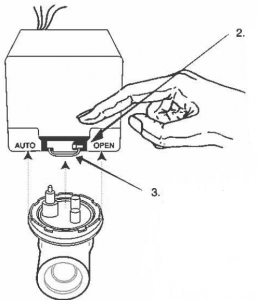
2. Place the manual operating lever in the OPEN position.3. Remove actuator by depressing locking button and lifting straight up
MOUNTING THE ACTUATOR:
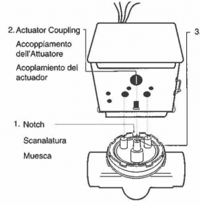
Ensure shaft slot pointstowards notch on side ofbody for fitting intoengaging shaft
4. Make proper wiring connections. Tum power supply back on.
Read More About This Manual & Download PDF:
[xyz-ips snippet=”download-snippet”]