
Honeywell Wire Saver THP9045A

About the Wire Saver
A wire saver acts as a splitter for applications that do not include a 24-volt C wire. If your heating/cooling system does not include a C wire, install the wire saver in or near the main unit (furnace, air handler) of your heating/cooling system.
What tools do I need to install it?
- Small, flat screwdriver
- Two-sided mounting tape (included)
- Thermostat wire bundle, ends stripped (included)
Before you begin installation, view the video at http://hwll.co/wiresaver
Step 1 Verify that you need a wire saver
Important! Ensure that the system is OFF (Quick Start Guide Step 1.1)
Complete Steps 1.1 through 1.6 in the Quick Start Guide.
- Identify existing wires and verify that there is no C wire (Quick Start Guide Step 1.2). If you have a C wire, you do not need to install the wire saver.
- If your old thermostat has no C wire connector but the wire bundle from your heating/ cooling system includes an extra wire not connected to the old thermostat, you can use that wire to connect your Wi-Fi thermostat’s C terminal. You do not need to use the wire saver. Refer to the Alternate Wiring video at wifithermostat.com/videos Take a photo of the wire connections (Quick Start Guide Step 1.2) or make notes to carry to your heating/cooling system.
Step 2 Wire the thermostat
At your new thermostat, for each wire:
- Loosen the screw, insert wire on inside edge of thermostat terminal, then tighten screw.
- Verify wire is firmly secured by gently pulling on wire.
- Repeat steps 1 and 2 for all wires.
- Match the wires labeled R and W to the R and W terminals.
- Match the wire labeled Y to the C terminal.
- Match the wire labeled G to the K terminal.
- Push any excess wire back into the wall opening after all wires are installed.Note: The wiring for your application might be different from the wiring shown here.
Step 3 Mount the wire saver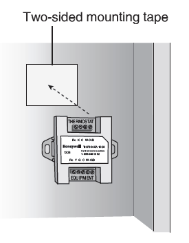
Mount the wire saver to a surface near the terminal block for the heating/cooling system.
- Locate the terminal block in your heating/cooling system to which the thermostat wires are attached. You may need to open or remove the front panel/door. If you are unsure how to do this, refer to your heating/cooling system documentation.
- Peel paper from one side of the included twosided mounting tape.
- Attach the sticky side to a suitable surface (such as the furnace wall or floor) that is close enough to the terminal block for the shortest wire to reach the wire saver.
- Peel the paper from the outer surface of the mounting tape and attach the wire saver with the terminal block labeled THERMOSTAT at the top.
Step 4 Select a wire configuration
Examine the labels on the terminal block for the existing thermostat wires. Determine which of the following combinations matches your setup:
- Single stage system (1 heat and 1 cooling stage) uses wires R or Rc, Y, G, W
- Two stage heat, single stage cooling system uses wires R or Rc, Y, G, W, W2
- Two stages for each heating and cooling uses wires R or Rc, Y, Y2 G, W, W2If none of these combinations matches what you see, call customer service for further instructions.
Step 5 Connect the wire saver
Connecting the wire saver involves two main actions: moving some wire connections from the terminal block in your heating/cooling system to the THERMOSTAT terminal block of the wire saver and using the included wire bundle to connect the terminal block on the equipment to the EQUIPMENT block on the wire saver.To connect the wire saver, follow the instructions and diagram for your setup as determined in Step 4.
- Follow instructions under 5a if you have a single stage setup.
- Follow instructions under 5b if you have two-stage heat, single-stage cooling.
- Follow instructions under 5c if you have two-stage heating and cooling.
5a Wire single-stage equipment
- Disconnect the R wire from your heating/cooling system’s terminal block.
- Connect the R wire to the Rc terminal on the THERMOSTAT end of the wire saver.
- Disconnect the W wire from the heating/cooling system; connect it to W on the THERMOSTAT end of the wire saver.
- Disconnect the G wire; connect it to K on the THERMOSTAT end of the wire saver.
- Disconnect the Y wire; connect it to C on the THERMOSTAT end of the wire saver.
- Connect stripped ends of the included wire bundle to the terminals labeled EQUIPMENT on the wire saver in this color order:
- Connect red to Rc
- Connect yellow to Y
- Connect green to G
- Connect blue to C
- Connect white to W
- Connect the other set of stripped ends to the terminals on your heating/cooling system following the same color order.
Wiring diagram: Single-stage equipment
When you complete the steps above, your wire saver and heating/cooling system will be wired as shown.
5b Wire two-stage heat, single-stage cooling
- Do not disconnect the W2 wire from your heating/cooling system.
- Disconnect the R wire from your heating/cooling system’s terminal block.
- Connect the R wire to the Rc terminal on the THERMOSTAT end of the wire saver.
- Disconnect the W wire from the heating/cooling system; connect it to W on the THERMOSTAT end of the wire saver.
- Disconnect the G wire; connect it to K on the THERMOSTAT end of the wire saver.
- Disconnect the Y wire; connect it to C on the THERMOSTAT end of the wire saver.
- Connect stripped ends of the included wire bundle to the terminals labeled EQUIPMENT on the wire saver in this color order:
- Connect red to Rc
- Connect yellow to Y
- Connect green to G
- Connect blue to C
- Connect white to W
- Connect the other set of stripped ends to the terminals on your heating/cooling system following the same color order.
Wiring diagram: Two-stage heat, single-stage cooling
When you complete the steps in 5b, your wire saver and heating/cooling system will be wired as shown.
5c Wire two-stage heat, two-stage cooling
- Do not disconnect the W2 or Y2 wires from your heating/cooling system.
- Disconnect the R wire from your heating/cooling system’s terminal block.
- Connect the R wire to the Rc terminal on the THERMOSTAT end of the wire saver.
- Disconnect the W wire from the heating/cooling system; connect it to W on the THERMOSTAT end of the wire saver.
- Disconnect the G wire; connect it to K on the THERMOSTAT end of the wire saver.
- Disconnect the Y wire; connect it to C on the THERMOSTAT end of the wire saver.
- Connect stripped ends of the included wire bundle to the terminals labeled EQUIPMENT on the wire saver in this color order:
- Connect red to Rc
- Connect yellow to Y
- Connect green to G
- Connect blue to C
- Connect white to W
- Connect the other set of stripped ends to the terminals on your heating/cooling system following the same color order.
Wiring diagram: Two-stage heat, two-stage cooling
When you complete the steps in 5c, your wire saver and heating/cooling system will be wired as shown.
Example wire saver setup: before and after
The instructions are for changing wiring at your main heating/cooling system. These images show the relationships between your thermostat and heating/cooling system before and after installing the wire saver.
Step 6 Close the equipment door
Close or put back door to the heating and cooling system so the interlock switch will allow the system to be turned on for the heating/cooling system and thermostat display. Your thermostat display will not turn on if the door/panel is not closed.
Step 7 Follow instructions in Quick Start Guide
Continue with Step 1.8 in the Quick Start Guide
Automation and Control SolutionsHoneywell International Inc.1985 Douglas Drive NorthGolden Valley, MN 55422wifithermostat.com® U.S. Registered Trademark. © 2014 Honeywell International Inc. 33-00042—02 M.S. 06-14 Printed in U.S.A.![]()
[xyz-ips snippet=”download-snippet”]