![]()

Instruction Manual

NOTICE
l instructions, warranties, and other collateral documents are subject to change at the sole discretion of Horizon Hobby, LLC. For up-to-date product literature, visit www.horizonhobby.com or towerhobbies.com and click on the support or resources tab for this product.
MEANING OF SPECIAL LANGUAGE:
The following terms are used throughout the product literature to indicate various levels of potential harm when operating this product:WARNING: Procedures, which if not properly followed, create the probability of property damage, collateral damage, and serious injury OR create a high probability of superficial injury.CAUTION: Procedures, which if not properly followed, create the probability of physical property damage AND a possibility of serious injury.NOTICE: Procedures, which if not properly followed, create a possibility of physical property damage AND little or no possibility of injury.
 WARNING: Read the ENTIRE instruction manual to become familiar with the features of the product before operating. Failure to operate the product correctly can result in damage to the product, personal property and cause serious injury.This is a sophisticated hobby product. It must be operated with caution and common sense and requires some basic mechanical ability. Failure to operate this Product in a safe and responsible manner could result in injury or damage to the product or other property. This product is not intended for use by children without direct adult supervision. Do not use with incompatible components or alter this product in any way outside of the instructions provided by Horizon Hobby, LLC. This manual contains instructions for safety, operation, and maintenance. It is essential to read and follow all the instructions and warnings in the manual, prior to assembly, setup or use, in order to operate correctly and avoid damage or serious injury.
14+ AGE RECOMMENDATION: Not for children under 14 years. This is not a toy.
Safety Precautions and Warnings
As the user of this product, you are solely responsible for operating in a manner that does not endanger yourself and others or result in damage to the product or the property of others.
- Always keep a safe distance in all directions around your model to avoid collisions or injury. This model is controlled by a radio signal subject to interference from many sources outside your control. Interference can cause momentary loss of control.
- Always operate your model in open spaces away from full-size vehicles, traffic and people.
- Always carefully follow the directions and warnings for this and any optional support equipment (chargers, rechargeable battery packs, etc.).
- Always keep all chemicals, small parts and anything electrical out of the reach of children.
- Always avoid water exposure to all equipment not specifically designed and protected for this purpose. Moisture causes damage to electronics.
- Never place any portion of the model in your mouth as it could cause serious injury or even death.
- Never operate your model with low transmitter batteries.
- Always keep aircraft in sight and under control.
- Always use fully charged batteries.
- Always keep transmitter powered on while aircraft is powered.
- Always remove batteries before disassembly.
- Always keep moving parts clean.
- Always keep parts dry.
- Always let parts cool after use before touching.
- Always remove batteries after use.
- Always ensure failsafe is properly set before flying.
- Never operate aircraft with damaged wiring.
- Never touch moving parts.
WARNING AGAINST COUNTERFEIT PRODUCTS: If you ever need to replace your Spektrum receiver found in a Horizon Hobby product, always purchase from Horizon Hobby, LLC or a Horizon Hobby authorized dealer to ensure authentic high-quality Spektrum product. Horizon Hobby, LLC disclaims all support and warranty with regards, but not limited to, compatibility and performance of counterfeit products or products claiming compatibility with DSM or Spektrum technology.
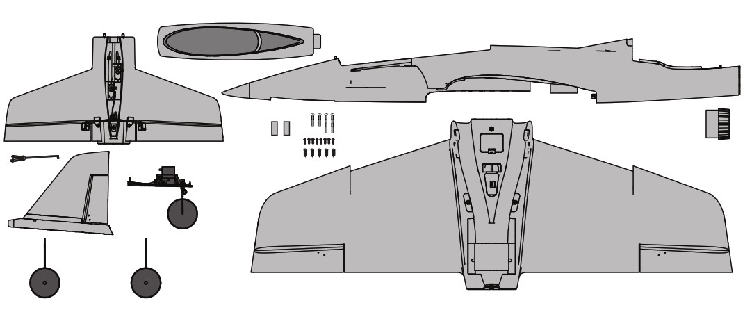
Box Contents

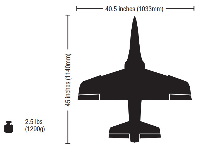
Specifications
| RTFREADY-TO-FLY | PNPPLUG-N-PLAY | |
| Motor: 2847-3200Kv 6-Pole Brushless motor (SPMXAM1100) | Installed | Installed |
| Fan Unit: 70mm Ducted Fan Unit (EFLM7450) | Installed | Installed |
| ESC: 70-Amp 3S/4S ESC w/Telemetry (SPMXAE0070) | Installed | Installed |
| Servos: (2) 9g mini Servo (SPMSA381)(3) 13g Digital MG Micro Servo (SPMSA382) | Installed | Installed |
| Receiver: Spektrum™ SRXL2™ DSMX Receiver w/Connector Installed (SPM4650C) | Installed | Required |
| Recommended Battery: 4000mAh 11.1V 3S Smart IC3™ 30C Li-Po (SPMX40003S30) | Included | Required |
| Recommended Battery Charger:S120 USB-C SMART Charger, 1x20W (SPMXC1020) | Included | Required |
| Recommended Transmitter:Full-Range 2.4GHz with Spektrum™ DSM2® /DSMX® technology with programmable mixing and adjustable dual rates | Included | Required |
If you own this product, you may be required to register with the FAA. For up-to-date information on how to register with the FAA, please visit https://registermyuas.faa.gov/. For additional assistance on regulations and guidance on UAS usage, visit knowbeforeyoufly.org/.
| RECEIVER BIND INFORMATION | |
| Channels | 6 |
| Frequency | 2404 – 2476 MHz |
| Compatibility | DSM2 and DSMX |
| Optional Upgrades (not included) |
| Landing Assist Sensor (LAS) |
| When added, the LAS module will assist you with your landing approach and at approximately 1m from the ground, the LAS module will level out the aircraft, adjust throttle if needed, and then flare the aircraft just before touchdown. |
From the box to the air
| √ |
| 1. Remove and inspect contents. |
| 2. Read this instruction manual thoroughly. |
| 3. Charge the flight battery. |
| 4. Fully assemble the aircraft |
| 5. Make sure all linkages move freely. |
| 6. Install a fully charged flight battery in the aircraft. |
| 7. Check the Center of Gravity (CG). |
| 8. Set up your transmitter |
| 9. Bind the aircraft to your transmitter |
| 10. Place the aircraft into Experienced Mode (Mode switch position 2) for the Control Direction Test. Place the aircraft on the ground facing away from you. |
| 11. Perform the control direction test with the transmitter |
| 12. Adjust the flight controls and transmitter as needed. |
| 13. Place the aircraft into Beginner Mode (Mode switch position 0) for the SAFE Control Direction Test and takeoff. |
| 14. Perform SAFE Control Direction Test |
| 15. Find a safe open area to fly. |
| 16. Perform a radio system range test. |
| 17. Plan flight for flying field conditions. |
| 18. Set a flight time for: 5 minutes for initial flights. Depending on your battery selection,adjust timer. |
Charger Warnings
CAUTION: All instructions and warnings must be followed exactly.Mishandling of Li-Po batteries can result in a fire, personal injury, and/or property damage.
- NEVER LEAVE CHARGING BATTERIES UNATTENDED.
- NEVER CHARGE BATTERIES OVERNIGHT.
- By handling, charging, or using the included Li-Po battery, you assume all risks associated with lithium batteries.
- If at any time the battery begins to balloon or swell, discontinue use immediately. If charging or discharging, discontinue and disconnect. Continuing to use, charge or discharge a battery that is ballooning or swelling can result in fire.
- Always store the battery at room temperature in a dry area for best results.
- Always transport or temporarily store the battery in a temperature range of 40–120º F (5–49º C). Do not store battery or aircraft in a car or direct sunlight.If stored in a hot car, the battery can be damaged or even catch fire.
- Always charge batteries away from flammable materials.
- Always inspect the battery before charging and never charge dead or damaged batteries.
- Always disconnect the battery after charging, and let the charger cool between charges.
- Always constantly monitor the temperature of the battery pack while charging.
- ONLY USE A CHARGER SPECIFICALLY DESIGNED TO CHARGE LI-PO BATTERIES. Failure to charge the battery with a compatible charger may cause fire resulting in personal injury and/or property damage.
- Never discharge Li-Po cells to below 3V under load.
- Never cover warning labels with hook and loop strips.
- Never charge batteries outside recommended levels.
- Never attempt to dismantle or alter the charger.
- Never allow minors under the age of 14 to charge battery packs.
- Never charge batteries in extremely hot or cold places (recommended between 40–120° F or 5–49° C) or place in direct sunlight.
Charge the Flight Battery
The recommended battery for the E-flite Habu STS aircraft, included with the RTF version, is an 11.1V, 4000mAh 3S 30C Smart Technology LiPo battery with an IC3™ connector (SPMX40003S30). If using a different battery, the battery should be of similar capacity, dimensions, and weight to fit in the fuselage. The aircraft electronic speed control is equipped with an IC3 device connector. Ensure the battery chosen is compatible. Always ensure the model balances at the recommended center of gravity (CG) with the chosen battery. Follow your chosen battery and battery charger instructions to charge the flight battery.
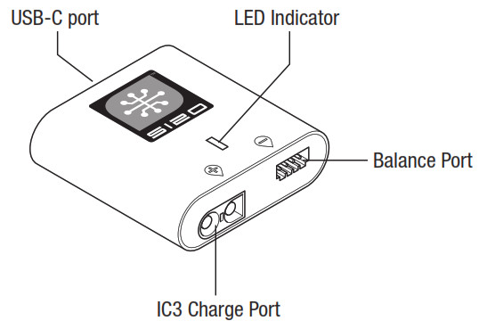
RTF Smart Technology Battery and S120 Charger, Specifications and OperationThe Spektrum S120 SMART Technology battery charger included with the RTF version of the aircraft is compatible only with Spektrum SMART 2-3 cell LiPo batteries or 6-7 cell NiMH batteries. It is not compatible with any other battery chemistries or non-SMART batteries.A USB power supply is required for use. A USB-C QC-type power supply is recommended for the fastest charge times.
| S120 Specifications | |
| Input | USB Type C, power supply not included |
| Input Voltage | 5V-12V |
| Charge Power | 18W max (dependant on the power supply) |
| Compatible USB Power Adaptor | 5V/1A, 5V/2A, USB Quick Charge (QC) 2.0/3.0 |
| Battery Connector | IC3™ and balance connector |
| Battery Types | LiPo, NiMH (Spektrum SMART Batteries only ) |
| Cell Count | 2-3 cell LiPo, 6-7 cell NiMH |
| Max Output Voltage | 13.05V |
| Max Output Current | Up to 2A |
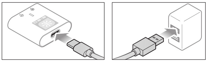
To charge the included flight battery:1. Using the supplied Type-C USB cable, connect the S120 charger to a USB power supply (not included ).
2. Insert the Spektrum SMART Battery IC3 connector (A) into the charger IC3 port, and insert the battery balance lead (B) into the charger balance port. Both the IC3 and balance connectors must be connected for the charging process to begin. The battery may be disconnected from the charger at any time to stop the charging process.
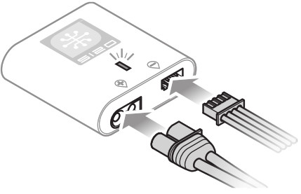
IMPORTANT: SMART NiMH batteries do not have a balance connector.3. Disconnect the IC3 and balance connectors when the charge and balance cycles are complete, as indicated by the LED.4. The LED indicator will glow solid red to indicate a charging error. Follow the operation steps to ensure proper connection is used to charge the battery.Refer to the LED indicator table for charger status.IMPORTANT: Connecting a non-SMART battery will cause a charge error and the S120 will not recognize or charge the battery.
| LED Indicator | |
| Power On | USB 5V: White LEDUSB Quick Charge 2.0/3.0: Blue LED |
| LiPo: Purple LED
NiMH: Yellow LED |
Battery Capacity |
| Less Than 25% | Single Flash |
| 25% – 75% | Double Flash |
| 76% – 99% | Triple Flash |
| Charge Complete | Green LED (Solid) |
| Error | Red LED (Solid) |
Transmitter
RTFREADY-TO-FLY
Installing the Transmitter BatteriesYour Spektrum DXS Transmitter comes prebound to the aircraft.Remove the battery cover, install the four included batteries (noting proper polarity) and reinstall the battery cover.Low Battery AlarmWhen the transmitter battery voltage drops below 4.7 volts, an alarm sounds, and the voltage LEDs flash. The batteries must be replaced immediately. If this happens while flying, land your aircraft as soon and as safely as possible.CAUTION: If using rechargeable batteries, charge only rechargeable batteries. Charging non-rechargeable batteries may cause the batteries to burst, resulting in injury to persons and/or damage to property.
![]()
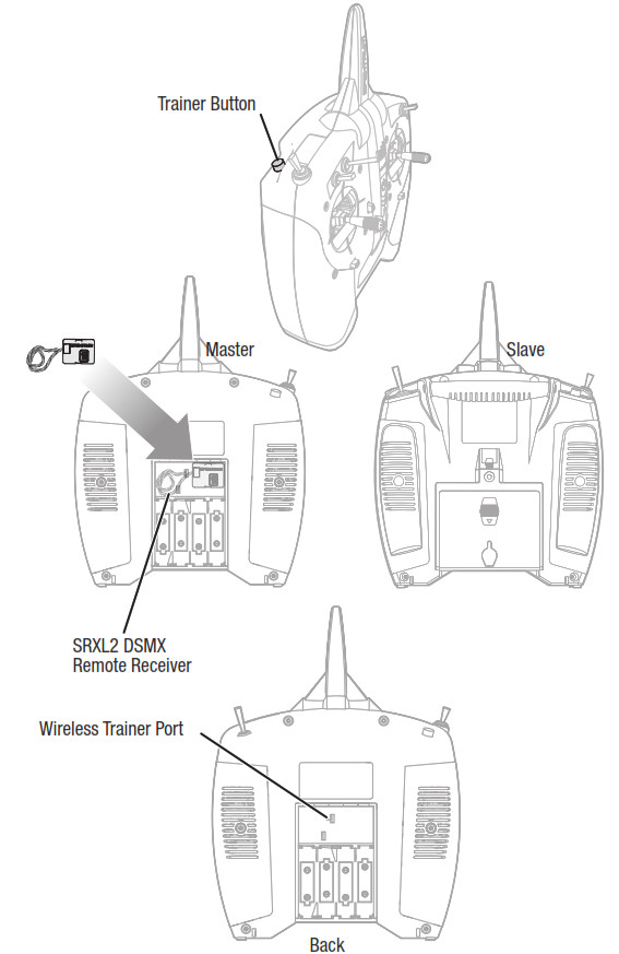
Explanation of DXS Transmitter LEDs, Switches, and Modes for the Habu STS.Trainer/Bind/Panic Button (I button):This switch is used as both the trainer and bind switch as well as the Panic Switch for your Habu STS. For complete binding instructions, refer to the binding section below. When using the trainer function, connect the SRXL2 DSMX remote receiver (SPM9747, sold separately) into the wireless trainer port of the master (instructor) transmitter. The master transmitter must be powered ON and bound to the aircraft receiver. The slave transmitter must be powered OFF. Any time you press and hold the trainer button on the master, it will give control authority to the slave. Releasing the trainer button returns control to the master.IMPORTANT: The slave transmitter must always have the same settings as the master. See Flight Training section for setup of other Spektrum Transmitters.Hi/Lo Rate Switch (F Switch):This switch supports high and low rate functions on aileron, elevator, and rudder channels. In the upper, or “HI” position, servo travel is 100% on these channels. In the lower, or “LO,” position, servo travel decreases to 70%. This switch lets you quickly change control rates from high for aggressive maneuvers to low for smooth, precise maneuvers. When learning to fly, use low rate.Flight Mode Switch (A Switch):This switch is used to select the SAFE Flight mode. For other conventional receivers, this switch controls a servo connected to the Channel 5/Gear port.
![]()
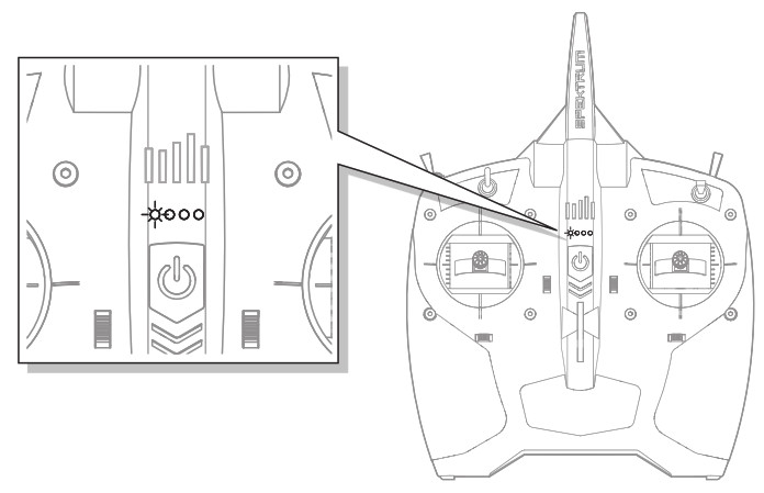
RGB LEDs:Flashing with beeps- Bind mode when Trainer (Bind) switch is held and the transmitter is powered on (see Binding instructions).Pulsates with one low tone beep every 2 seconds (when transmitter battery voltage drops below 4.7 volts). Replace the transmitter batteries immediately. If this happens while flying, land your aircraft as soon and as safely as possible.
Battery Voltage LevelThe included DXS transmitter includes a new flight battery voltage level indicator feature.LED SMART Battery voltage indication is based on current-voltage and will change with throttle/power usage. When the throttle is increased, voltage drops, causing the bars to indicate lower power (e.g., fewer LEDs solid or flashing.) When the throttle is lowered to idle/off, the bars recover (e.g., more LEDs solid or flashing). LED bars will rise and lower depending on throttle/power usage.
The SMART Battery low voltage alarm sounds when the ESCs are close to reaching low voltage cutoff. The alarm will sound for 25 seconds. If the throttle is lowered to allow voltage recovery, the alarm will stop early. Land the aircraft when the alarm sounds.After landing, reset the SMART Battery low voltage warning by either (1) powering cycling the DXS transmitter, or (2) disconnecting the battery from the aircraft for more than 15 seconds or until the LED voltage indication bars go out.Connect a fully charged battery to the aircraft, which will ensure the SMART Battery low voltage warning resets prior to the next flight.
Transmitter Setup
If using any DSMX transmitter other than the included DXS (3 position gear switch, RTF only) the radio will have to be configured correctly for the SAFE system to work properly.
• SAFE Flight mode is selected using Channel 5 signal (high, middle, low)• Panic mode is selected with Channel 6 signal (high, low)
Refer to your transmitter’s manual for more information about transmitter setup.If using a 2 position switch for SAFE flight modes, only Beginner andExperienced modes will be active.BNF Transmitter Telemetry SetupIf the transmitter that you intend to use with this aircraft is not displaying telemetry data, visit Spektrumrc.com and update your firmware. With the latest firmware installed on your transmitter, the telemetry option should now be functional on your transmitter.
| Computerized Transmitter Setup(DX6 Gen2, DX6e,DX7 Gen2, DX8 Gen2, DX9, iX12, DX18 and DX20) | |
| Start all transmitter programming with a blank model(do a model reset), then name the model. | |
| Set Aileron, Elevator, and Rudder Rates to: | HIGH 100% |
| LOW 70% | |
| DX6DX6eDX8DX9iX12DX20 | Go to the SYSTEM SETUP |
| Set MODEL TYPE: AIRPLANE | |
| Go to CHANNEL ASSIGN:click NEXT to go to Channel Input Config: GEAR: B, AUX1: I | |
| Go to the FUNCTION LIST | |
| Go to Throttle Cut:set to Switch H, Position: —100 | |
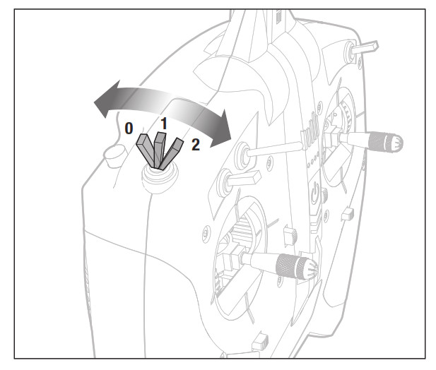
| Resulting in: | Switch H operates Throttle Cut, position 0 is normal and position 1 cuts power to the throttle. Switch B operates the 3 SAFE modes(0 beginner/1 intermediate/2 experienced).Button I operates PANIC mode. |
SMART Technology Electronic Speed Control (ESC)The Habu STS is equipped with an exclusive Smart ESC that can provide a variety of real-time power system related telemetry data including motor RPM, current, battery voltage and more to compatible Spektrum AirWare™ equipped transmitters (including the DX6e and 8e, DX6 and 8 G2, the DX9, iX12, and others) while you fly.Access the telemetry data by plugging the ESC into channel 6 on the A3230 Flight Controller. The ESC will send the below information to the flight control and the information will be displayed on the compatible transmitter.
• RPM• Voltage• Current• Throttle• FET Temperature• BEC Temperature
ESC StatusRPM: 0Volts: 0.0VMotor: 0.0A 0% OutputThrottle: 0%Fet Temp: 0.0CBEC: 0.0C 0.0A 0.0V
Dual Rates
The included DSMX® full range transmitter features dual rates to allow you to select the amount of travel that you want from the control surfaces.
| Dual Rate | High Rate | Low Rate |
| Aileron | 100% | 70% |
| Elevator | 100% | 70% |
| Rudder | 100% | 70% |
Assemble the Aircraft
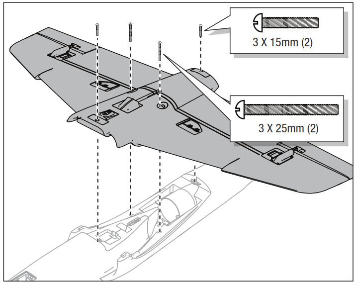
Wing Installation
- Position the wing and fuselage with the bottom side facing up.
- Align and attach the wing to the fuselage.
- Secure the wing to the fuselage using the 4 screws. Use two 3 x 15mm screws for the front and back holes. Use two 3 x 25mm screws for the side holes.
- Disassemble in reverse order.
Assemble the Aircraft
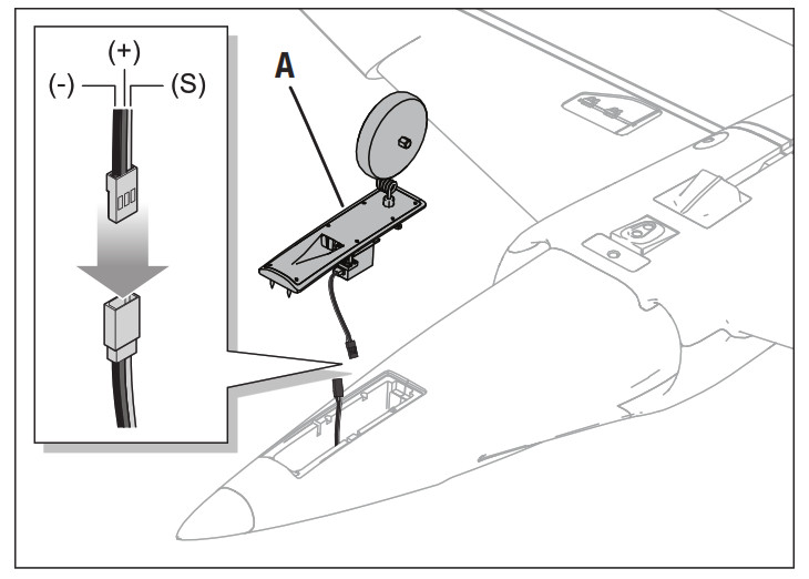
Nose Gear Installation
- Connect the nose gear assembly servo connector to the nose gear servo extension in the fuselage. When connecting the servo connectors match the colored wires when inserting the male servo plug in the female. Orange is the signal wire (S) red is positive (+) brown is negative (-).
- Install the nose gear assembly (A) into the fuselage with the air vent facing forward.
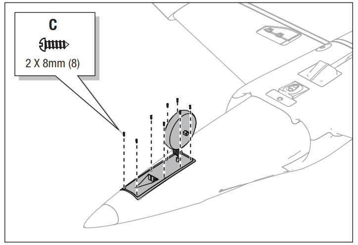
- Secure the nose gear assembly using the eight 2 x 8mm screws (C).Disassemble in reverse order.
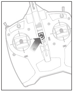
Main Gear Installation
- Position the aircraft so the bottom of the wing faces up.
- Insert the main gear strut (A) into the gear plate hole located on the wing.
- Carefully turn each strut in the gear plate until the horizontal section (B) of the strut gently snaps into place. Where needed, disassemble in reverse order.

Assemble the Aircraft
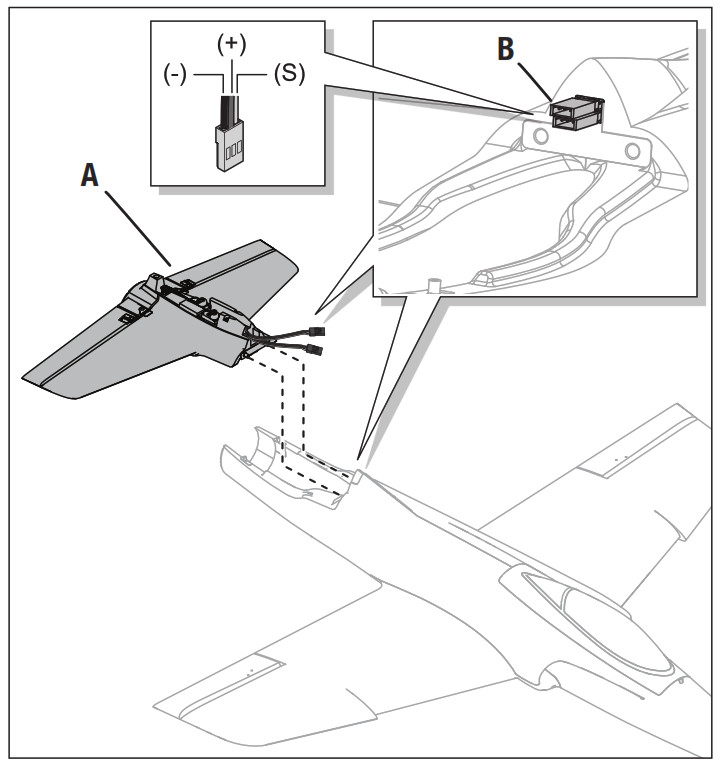
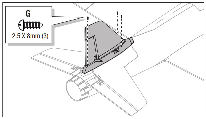
Tail Installation
- Loosely align the horizontal stabilizer assembly (A) on the rear of the fuselage.
- Correctly connect the rudder and elevator servo connectors (B) to the marked connectors in the fuselage. Orange is the signal wire (S) red is positive (+) brown is negative (-).IMPORTANT: Ensure no wires are pinched or damaged when the tail unit is attached to the fuselage.
- Install and secure the tail assembly on the top of the rear fuselage using two screws (C).
- Manually position the rudder servo arm as shown (D).
- Align and press the tail cone (E) on the rear of the fuselage and secure the cone in place with included tape (F).
- Align the vertical fin with the fuselage and guide the rudder servo arm through the hole of the vertical fin base.
- Secure the vertical fin to the fuselage with three 2.5 x 8mm screws (G).
- Attach the Z-bend of the linkage (H) in the second hole of the rudder servo arm (I) (the hole next to the outermost hole).
- Attach the linkage clevis (J) to the outer hole of the rudder control horn (K). Ensure the tube (L) tightens the clevis on the control horn.Where needed, disassemble in reverse order.

Tail Installation Continued

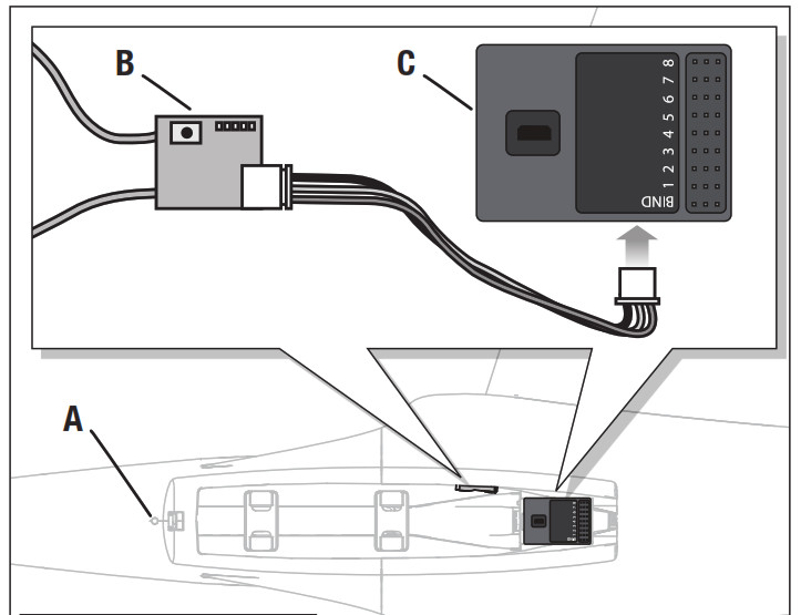
PNP Receiver Selection and Installation
SRLX DSMX Receiver and Flight Controller InstallationInstall the Spektrum SRLX DSMX receiver (SPM4650C) and flight controller (SPMA3220B) combination to experience the HABU STS with SMART Technology.
- Press the latch button (A) and remove the canopy.
- Using double-sided servo tape, (not included) mount the SRLX DSMX receiver (B) to the interior side panel of the receiver compartment.
- Connect the SRLX DSMX receiver to the flight controller (C).
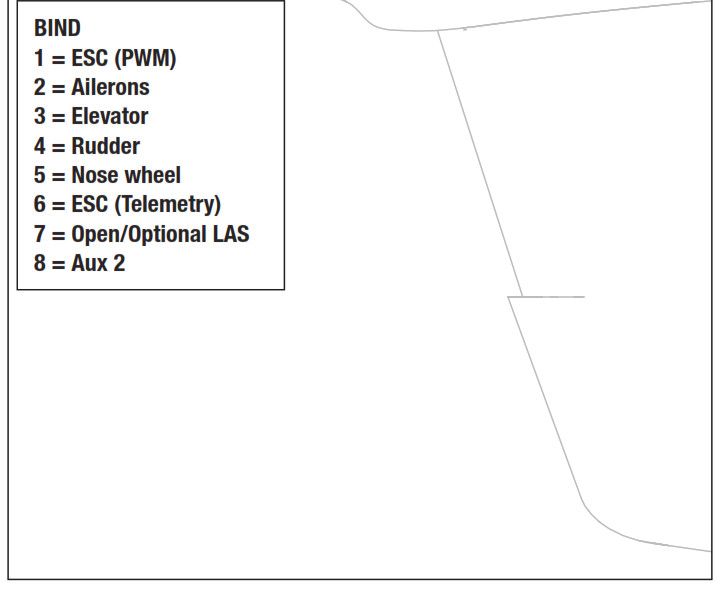
- Attach the appropriate control surfaces to their respective ports on the flight controller using the table at the right.
- Using double-sided servo tape, (not included) the flight controller to the platform at the rear of the receiver compartment as shown.
The flight controller should be mounted in the orientation shown, parallel to the length of the fuselage, with the label facing up and the servo ports facing the rear of the aircraft. The orientation of the flight controller is critical for all AS3X® and SAFE® technology setups.CAUTION: Incorrect installation of the flight controller could cause a crash.
Transmitter and Receiver Binding
Binding is the process of programming the control unit to recognize the GUID (Globally Unique Identifier) code of a single specific transmitter.The aircraft should be bound to the transmitter at the factory, but if you need to re-bind them, follow these steps. If your aircraft does not respond to the transmitter when the batteries in the aircraft and transmitter are fully charged, your aircraft and transmitter may need to be re- bound using the instructions in the chart.IMPORTANT: The throttle will not arm if the transmitter’s throttle control is not put at the lowest position. If you encounter problems, follow the binding instructions and refer to the transmitter troubleshooting guide for other instructions. If needed, contact the appropriate Horizon Product Support office.* FailsafeIf the receiver loses transmitter communication, the failsafe will activate.When activated, failsafe moves the throttle channel to its preset failsafe position (low throttle) that was set during binding. All other channels move for the aircraft to slowly circle and descend until radio link is re-established.
| √ | Binding Procedure |
| 1. Make sure the transmitter is powered off. | 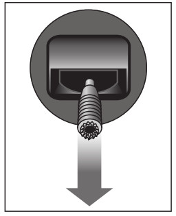 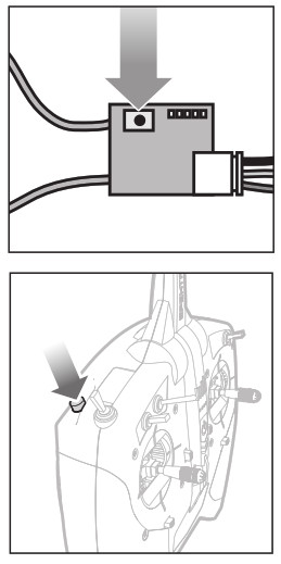
|
| 2. Make sure the transmitter controls are neutral, the throttle is in the low position, and the aircraft is immobile.* | |
| 3. Connect the flight battery to the ESC. The Flight Controller LED will begin to flash red and blue. | |
| 4. On the remote Spektrum receiver that is connected to the flight controller, press and release the bind button. The receiver LED will flash rapidly. | |
| 5. Press and hold the Bind button on the top of the transmitter while turning ON the power switch. | |
| 6. When the receiver binds to the transmitter, the receiver LED will be solid ON. | |
| Once bound the receiver and transmitter should retain their bind for future flights. | |
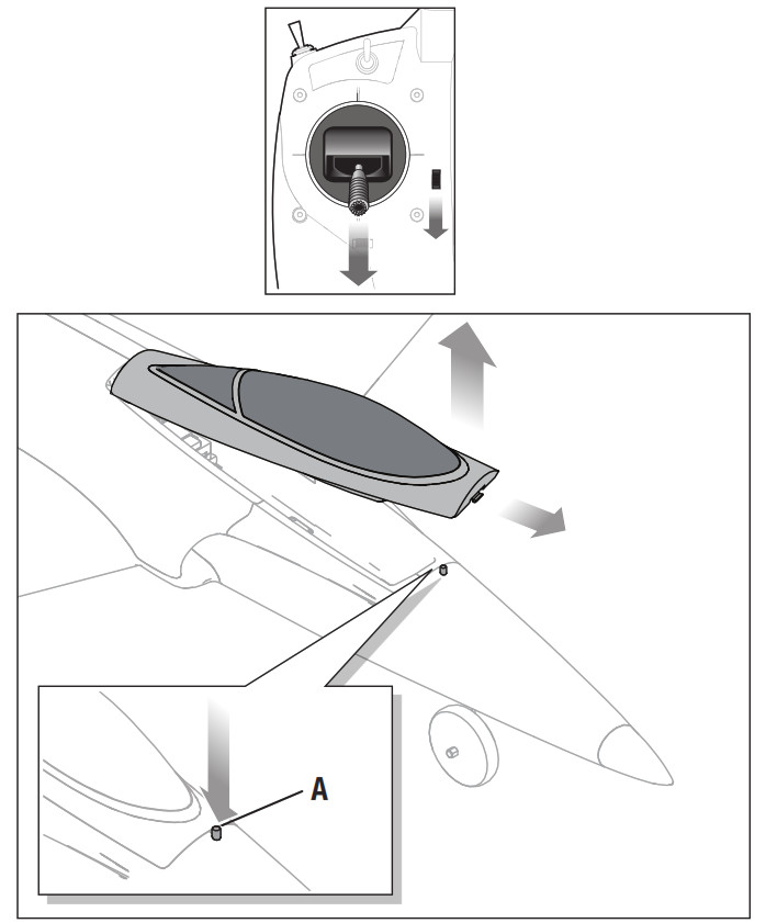
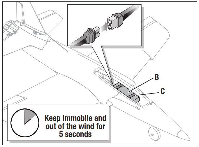
Flight Battery Installation, SAFE system and Electronic Speed Control (ESC) Arming
- Rest the aircraft on its landing gear on a flat surface.
- Lower the throttle and turn on the throttle hold switch, then power on the transmitter for at least 5 seconds.
- Press the latch button (A) and remove the canopy.
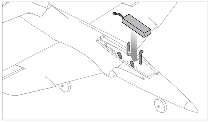
- Secure the flight battery (B) in the battery compartment using the hook and loop straps (C) so that the aircraft has a balanced Center of Gravity (CG).
- Connect the flight battery to the aircraft.TIP: Connect the battery to the flight controller plug before securing the battery. Then secure the battery with the hook and loop straps. Important: Before flying, refer to the “Verifying Your Aircraft’s Center of Gravity (CG)” section for details about final battery placement.6. Replace the canopy.The aircraft should be on level ground and must be kept immobile while the SAFE system initializes. If the aircraft does not initialize after about 30 seconds because of too much movement, disconnect and reconnect the flight battery to re-initialize the system.After the SAFE system initializes, the rudder will move back and forth, then come to neutral to indicate the SAFE system has initialized and is ready to operate. If you accidentally connect the battery while the throttle is not a its lowest position, the ESC will not arm the motor. Reduce throttle to lowest setting for motor to arm.
IMPORTANT: SAFE technology is not active until you advance the throttle past 25%. Once it is active, the control surfaces may move on the aircraft. This is normal. The SAFE technology will remain active until the ESC is turned off.
CAUTION: Always disconnect the Li-Po flight battery from the aircraft receiver when not flying to avoid over-discharging the battery. Batteries discharged to a voltage lower than the lowest approved voltage may become damaged, resulting in loss of performance and potential fire when batteries are charged.
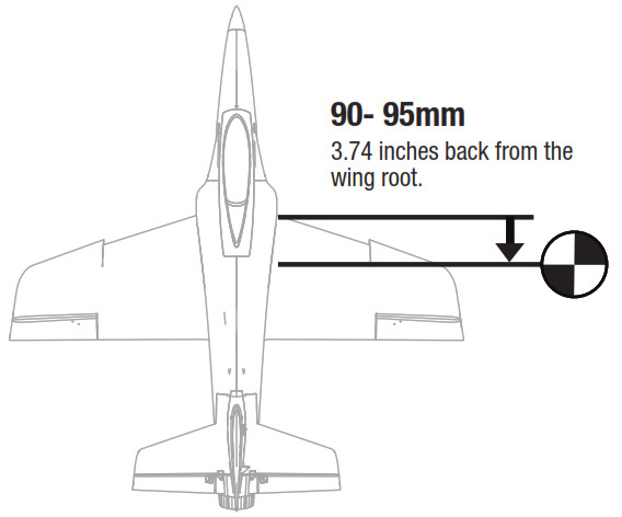
Center of Gravity (CG)
An aircraft with a correct CG has its weight balanced at a calculated point where the entire airframe will balance when suspended at that point. After installing the battery (in the recommended position) and before powering on the ESC switch, verify the CG by supporting the aircraft 90-95mm (approximately 3.74 inches) back from the wing root, as shown.3S 4000mAh Smart battery CG position- The battery is installed all the way forward in battery compartment. Only the front battery strap will be used.4S 4000mAh Smart battery CG position- The battery is installed centered in the battery tray, using both front and rear battery straps. Balance the aircraft on your fingertips near the fuselage under the wings.
- If the nose goes down, move the flight battery back until the aircraft balances.
- If the nose goes up, move the flight battery forward until the aircraft balances.
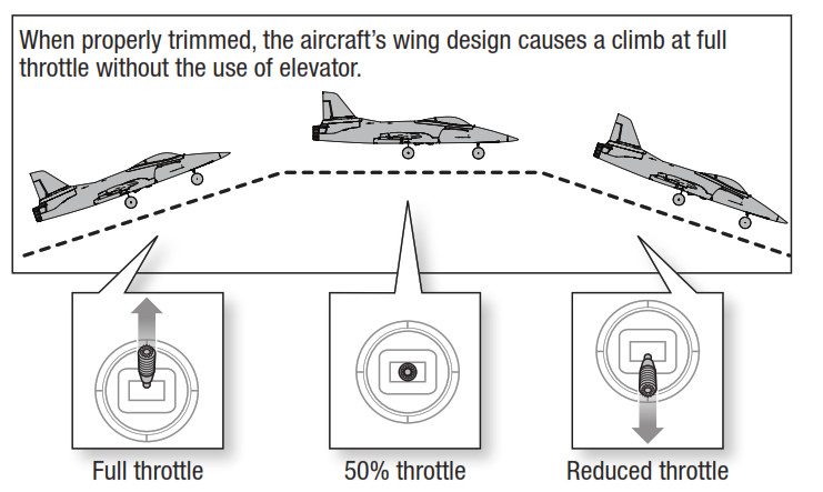
When flying with correct CG in beginner mode, the aircraft should climb gradually at full power and fly level at 50%–60% power with no elevator input. If the aircraft CG is too far forward (nose heavy), up elevator is required to fly level at 50%–60% power. If the aircraft CG is too far aft (tail heavy), down elevator is required to fly level. Adjust the battery position as needed.
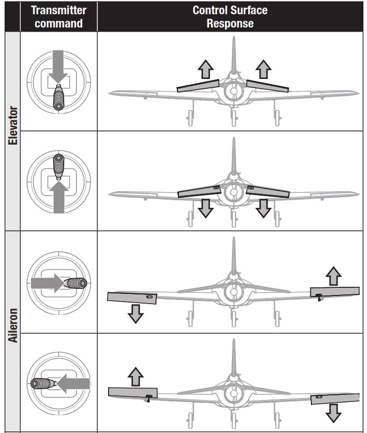
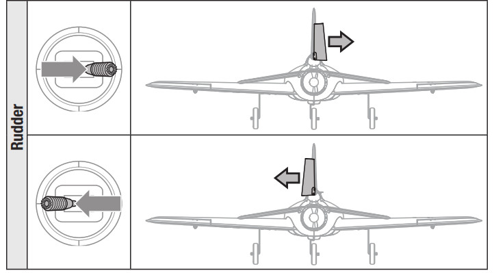
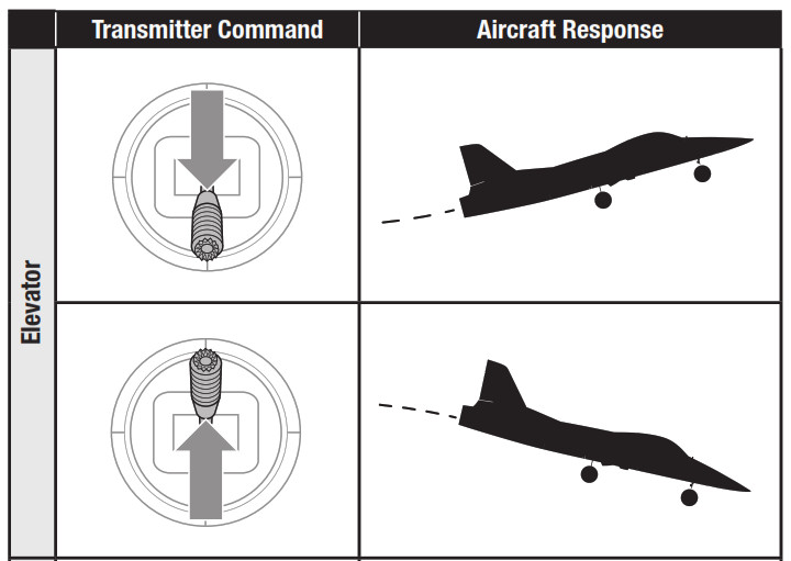
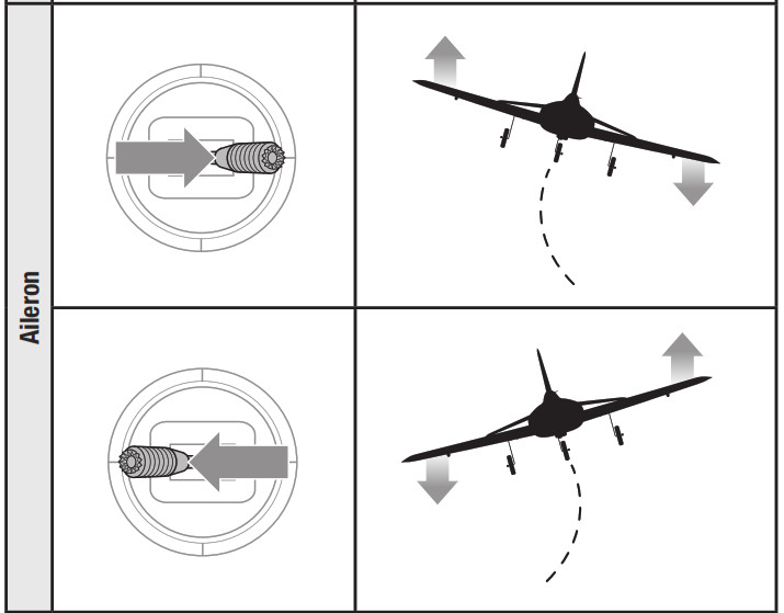
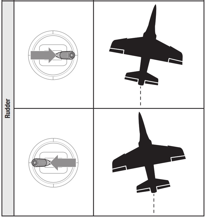
Control Direction Test
WARNING: Do not perform this or any other equipment test with the propeller installed on the aircraft. Serious injury or property damage could result from the motor starting inadvertently.
- Set the flight mode switch to Experienced mode (position 2).
- Keep the throttle at zero and place the model on level ground away from obstacles.
- Move the sticks on the transmitter as described in the table to ensure the aircraft control surfaces respond as shown.
If the control surfaces do not respond as shown, DO NOT FLY. Refer to the Troubleshooting Guide for more information. If you need more assistance, contact the appropriate Horizon Hobby Product Support department.If the aircraft responds as shown, continue on to the Flight Control section.
Choose a Flying Field
Consult local laws and ordinances before choosing a location to fly your aircraft.
In order to have the most success and to protect your property and aircraft, it is very important to select a place to fly that is very open.Remember, your aircraft can reach significant speeds when flying and can cover ground quickly. Plan on flying in an area that gives you more space than you think you need, especially with first flights.
The flying site should:
- Have a minimum of approximately 1300 feet(400m) of clear space in all directions.
- Be clear of people and pets.
- Be free of trees, buildings, cars, power lines or anything that could entangle your aircraft or interfere with your line of sight.
Range Test
WARNING: While holding the aircraft during the range test, always keep body parts and loose items away from the motor. Failure to do so could cause personal injury.
Before each flying session, and especially with a new model, you should perform a range check. If you have the PNP aircraft, refer to your transmitter manual to perform a range check of your system.
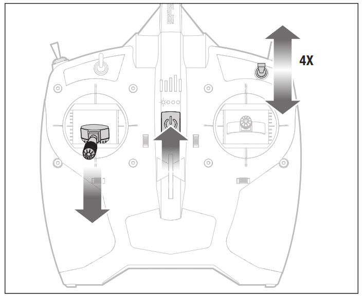
The RTF included DXS transmitter incorporates a range check mode to reduce the output power of the transmitter. Follow the directions below to enter range check mode for the DXS transmitter:
- Power on the transmitter for 5 seconds or more with the throttle stick and trim low. Plug in the aircraft battery and keep the aircraft immobile for 5 seconds.
- Face the model with the transmitter in your normal flying position.
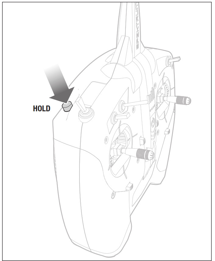
- Toggle (back and forth = 1 toggle) the HI/LO Rate switch rapidly 4 times and then press and hold the bind button. The transmitter LEDs will flash and the alarm will sound. The system is in range check mode. Do not let go of the bind button until you are finished with the range check.IMPORTANT: You must hold the BIND/Panic button during the entire range check process. Releasing the button will exit the range check mode.
- With the radio system powered on and the model restrained on the ground, stand 28 meters (90 feet) away from the model.TIP: In some aircraft, when the model is placed on the ground, the antenna(s) can be within inches of the ground. Close proximity of the antenna(s) to the ground can reduce the effectiveness of the range check. If you experience issues during the range check, restrain the model on a non-conductive stand or table up to 2ft (60cm) above the ground, then range check the system again.
- Move the transmitter rudder, elevator, aileron, and throttle control to ensure they operate smoothly at 28 meters (90 feet).
- If control issues exist, do not attempt to fly. Refer to the contact table at the end of this manual to contact Horizon Hobby product support. Also, see the Spektrum website for more information.
- When the range check is successfully completed, release the bind button to exit range check mode.
CAUTION: Due to the reduced output power of the transmitter, NEVER attempt to fly while the transmitter is in range check mode. Loss of control will occur.
Sensor Assisted Flight Envelope (SAFE) Technology Flight Modes
At any time during a flight you can switch between the 3 flight modes or use Panic recovery to get your aircraft to a safe flying attitude. Change between flight modes by changing the flight mode switch position.
Beginner Mode (position 0)
Flight Controller LED Blue
- Envelope limit: Pitch (nose up and down) and Roll (wing tips up and down) angles are limited to help you keep the aircraft airborne.
- Self-leveling: when the pitch and roll controls are returned to neutral, the aircraft returns to level flight.
- Stability assisted takeoff and landing.
- Throttle-based climb and descent.
Intermediate Mode (position 1)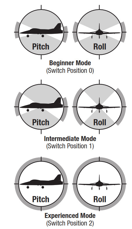 Flight Controller LED Purple• Natural Flight Experience: In normal training flight conditions, the pilot experiences natural AS3X® flight for smooth handling and outstanding precision.• Large Flight Envelope: The pilot is only prevented from entering extreme flight conditions outside the training flight envelope.TIP: When flying Intermediate Mode, the Habu STS will automatically be in beginner mode when below 100 feet.
Panic RecoveryThis function is intended to provide you with the confidence to continue to improve your flight skills. If you become disoriented or the aircraft is in an unknown or uncomfortable attitude in any flight mode:
- Press and hold the Bind/PANIC button on the transmitter and release the control sticks. The aircraft will immediately pull out of a dive and roll wings upright and level.IMPORTANT: The aircraft will recover to a safer attitude even if sticks are held while holding the PANIC button. However, release the control sticks for the quickest recovery.
- Release the PANIC button and continue your flight.
CAUTION: The Panic Recovery function will not avoid obstacles in the aircraft flight path. Sufficient altitude is required for the aircraft to return to straight and level flight if the aircraft is upside down when the panic function is applied.
Flight Control
IMPORTANT: Even though SAFE technology is a very helpful tool, the aircraft still needs to be flown manually. If incorrect input is given at lower altitudes or at slower speeds, the aircraft can crash. Study these control inputs and the aircraft response to each carefully before attempting your first flight. For first flights, set the SAFE® flight mode switch to Beginner Mode (position 0). For smooth control of your aircraft, always make small corrections. All directions are described as if you were sitting in the aircraft.
Flying faster or slower: When your aircraft is stable in the air, push the throttle stick up to make the aircraft go faster. Pull the throttle stick back to slow down. The aircraft will climb when the throttle is increased.Elevator up and down: Push the elevator stick forward to make the aircraft go down. Pull the elevator stick back to go up.Aileron right and left: Move the aileron stick right to make the aircraft roll or “bank” right. Move the aileron stick left to bank left.TIP: Always picture yourself in the aircraft when determining which way to bank the aircraft wings. When the aircraft is flying away from you, banking the aircraft right or left appears normal. When flying toward you, the aircraft will appear to bank the opposite direction to the control input given. This will become more instinctual with experience.
Rudder left and right: Push the rudder stick left or right to yaw or point the nose of the aircraft left or right. The rudder stick is also used to steer the aircraft left and right while taxiing on the ground.TIP: Similar to aileron control, picture yourself in the aircraft to determine which direction to point the nose whether you are flying away from yourself or toward yourself.
Flight Training
InstructionTo the new pilot:This aircraft is easy to fly and helps you apply beginner skills to flying; however, we recommend you get help from a qualified flight instructor for your first radio-controlled flights. Some model flying clubs provide flight training at their flying fields. Find a nearby flying club through your local hobby shop. In the U.S., visit the Academy of Model Aeronautics at www.modelaircraft.org for more information on clubs and flight instruction.
To the flight instructor:Feel free to experiment with the SAFE technology before instructing your student on this aircraft. The progressive switch positions in the SAFE technology are intended for a new pilot to learn with minimal instructor assistance. We recommend using Channel 5 Switch Position 1 to instruct a new pilot. Switch positions 0 and 2 may stabilize the aircraft more or less than you desire for instruction purposes.
RTFRADY-TO-FLY
DXS Wireless Trainer FeatureYour DXS transmitter may be connected to another transmitter through the SRXL2 DSMX Remote Receiver (SPM9747, sold separately).
The DXS transmitter is ideal as the master as it is compatible with all Spektrum transmitters when using this feature. Servo reversing and trims must be the same on both transmitters.
This “buddy box” approach has helped many new pilots get the feel for aircraft control with the close assistance of a flight instructor. Connecting two transmitters enables your flight instructor to hold the master transmitter while you hold the slave transmitter. While you learn to fly, the instructor holds the trainer switch to give you control of the aircraft. If you need help, the flight instructor can release the switch to take control.
IMPORTANT: If a transmitter other than the included DXS is used for master or slave, refer to Buddy Box Setup in this manual.
Remote Receiver Installation1. Open the battery door2. Connect the remote receiver cable to the wireless trainer port.3. Install the remote receiver in the cavity behind the battery door with double-sided tape.
Buddy Box SetupIMPORTANT: If using the buddy box option for training on a transmitter other than the included DXS use these settings for a Master and or Slave Transmitter. Failure to do so will not allow SAFE technology Flight modes to work correctly.
| Slave Transmitter Setup | |
| Slave Transmitter | Slave Setup |
| DX4e, DX5e (2pos) | Factory Trainer Settings |
| DX4e. DX5e (3pos) | Factory Trainer Settings |
| DXe | Factory Trainer Settings |
| DX6i | Factory Trainer Settings |
| DX7 | Factory Trainer Settings |
| DX6 DX9DX7s DX1 0tDX7(G2) DX18DX8 DX20DX8(G2) | Factory Trainer Settings |
IMPORTANT: If using the buddy box option the transmitter must be configured using the Transmitter Setup and Buddy Box setup charts.
| Master Transmitter Setup | |
| Master Transmitter DX4e, DX5e (2pos) | Master Setup |
| Factory Trainer Settings | |
| DX4e, DX5e (3pos) | Factory Trainer Settings |
| DXe | Factory Trainer Settings |
| DX6i | Factory Trainer Settings |
| DX7 | Trainer to Normal |
| DX6 DX9DX7s DX1 OtDX7(G2) DX18DX8 DX20DX8(G2)* | Activate Programmable Master and insurechannels Thro – Aux 1 are set to slave. |
Preflight Checklist
| √ |
| 1. Find a safe open area to fly. |
| 2. Charge the flight battery. |
| 3. Install a fully charged flight battery in the aircraft. |
| 4. Make sure all linkages move freely. |
| 5. Check the Center of Gravity (CG). |
| 6. Perform the control direction test |
| 7. Perform a radio system range test. |
| 8. Plan flight for flying field conditions. |
| 9. Set a flight time for:4-6 minutes using a 3000mAh 3S battery pack.8-10 minutes using a 4000mAh 3S battery pack. |
| 10. Have Fun! |
Flying
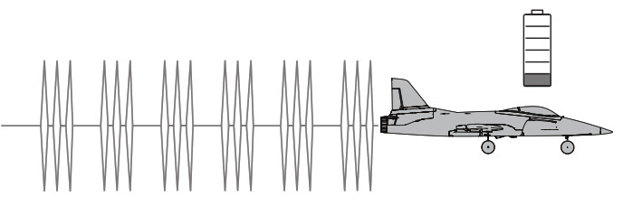
TakeoffSet the flight mode switch to Beginner Mode (position 0) for your first flights. Set a flight timer for 5 minutes for initial flights. Depending on your battery selection, adjust timer.TIP: The included DXS transmitter includes a new flight battery voltage level indicator feature. See page 6 for more details.TIP: When battery reaches LVC, the motor will pulse on/off for about 30 seconds before motor shuts off indicating it is time to land. Adjust timer accordingly.
Ground LaunchOnce the aircraft is ready for flight, slowly advance the throttle to start the takeoff roll into the wind. Small rudder inputs may be required for heading correction as the aircraft will begin a slow climb out as the throttle is advanced.TIP: Rudder/nose wheel control throw is automatically set for taxi mode in beginner mode when on the ground and under 6 meters of altitude.This provides more control to taxi the aircraft and yaw control during landings.Once airborne, rudder control throw is automatically reduced to beginner flight mode.

In FlightLet the aircraft climb at full throttle, into the wind, until the aircraft reaches about 50 feet. Gradually turn the aircraft away from you while still maintaining altitude. Climb to about 200 feet and reduce the throttle to about half throttle stick position. Try not to get the aircraft too high or far away. It will make it difficult to see.Make small and gentle stick movements to see how the aircraft responds.
Flying with the nose pointed toward you is one of the hardest things to do when learning to fly. Practice flying in large circles high off the ground.
If you lose the orientation of the aircraft, press and hold the PANIC button and the aircraft will return to level flight.
NOTICE: If a crash is imminent, activate throttle hold or quickly lower the throttle and throttle trim. Failure to do so could result in extra damage to the airframe, as well as damage to the ESC and motor.
Low Voltage Cutoff (LVC)LVC is a function built into your ESC to protect the battery from over-discharge. When the battery charge is low, LVC limits power supplied to the motor. The aircraft will begin to slow and you will hear the motor pulse. When the motor power decreases, land the aircraft immediately and recharge the flight battery.NOTICE: Repeated flying to LVC will damage the battery.Disconnect and remove the Li-Po battery from the aircraft after use to prevent trickle discharge. Charge your Li-Po battery to about half capacity before storage. During storage, make sure the battery charge does not fall below 3V per cell.
Land the aircraft
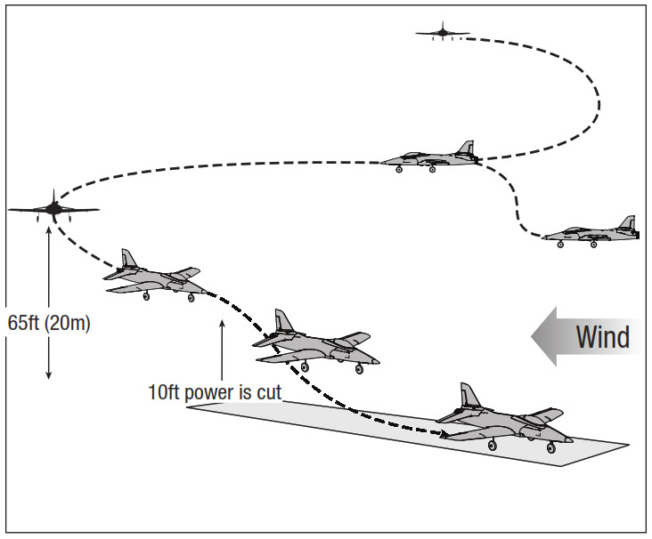
- Reduce the throttle to around 50% to slow the airspeed.
- Fly the aircraft downwind past the end of the runway.
- Turn the aircraft into the wind and line the aircraft up with the runway center line.
- Decrease the throttle further and begin descending towards the runway, keeping the wings level during approach. Try to have the aircraft at 10ft altitude as it passes over the threshold of the runway.
- As the aircraft passes over the threshold of the runway slowly decrease the throttle.
- Just as the aircraft is about to touch down, gently pull back on the elevator to raise the nose and flare for a gentle landing.
NOTICE: If a crash is imminent, activate throttle hold or quickly lower the throttle. Failure to do so could result in extra damage to the airframe, as well as damage to the ESC and motor.IMPORTANT: When finished flying, never keep the aircraft in the sun. Do not store the aircraft in a hot, enclosed area such as a car. Doing so can damage the foam.
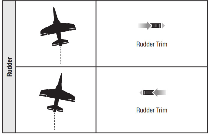
Trimming the Aircraft
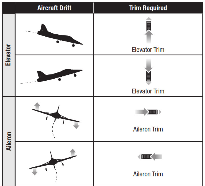
Adjusting Trim in flightIf your aircraft does not fly straight and level at half throttle with the sticks at neutral, fly into the wind and adjust the trim sliders as indicated in the table until the aircraft maintains a reasonably straight and level flight path.• Trimming is best done in calm wind conditions.• The SAFE flight mode switch should be set to Experienced mode (position 2) before adjusting the trims.
After the aircraft is trimmed in flight, land the aircraft and proceed to the Manually Adjusting Trim section to set the trim mechanically.
The included RTF DXS transmitter features electronic trim buttons. The transmitter emits a faint beep with each click of the trim buttons in either direction. Holding the button in either direction quickly adjusts the trim several steps until the button is released or until the trim reaches the end of its travel. If the trim button does not beep when clicked, the trim is at the far end of its travel. Center trim is indicated by a slightly louder beep.TIP: Trim the aircraft at a sufficient altitude of 30 meters (about 100’). Having an experienced flight instructor trim your aircraft during the first flight is recommended.
Manually Adjusting TrimThe SAFE flight mode switch should be set to Experienced mode (position 2) before manually adjusting the trim settings.The aircraft should be kept still while performing manual adjustment of trim.With the trim settings from the trim flight still set in the transmitter, take note of the positions of each of the control surfaces, one at a time.Adjust the clevis on each control surface to position the surface the same as it was with the trim offset.1. Remove the clevis from the control horn.2. Turn the clevis (as shown) to lengthen or shorten the pushrod.3. Close the clevis onto the control horn and slide the tube towards the horn to secure the clevis.4. Move to the next control surface.When you have all of the surface trims centered, return the trim settings on the transmitter to neutral by pushing the trim buttons for each surface until the transmitter emits a loud beep indicating center trim.

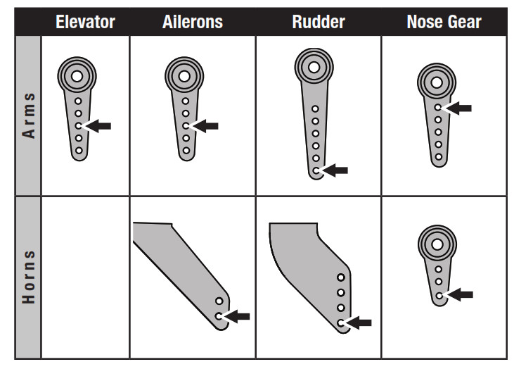
Factory settings for the Control Horns and Servo Arms
The Illustration shows recommended hole settings in the servo arms and control horns.
Post Flight
- Disconnect the flight battery from the ESC (Required for Safety and battery life).
- Power OFF the transmitter.
- Remove the flight battery from the aircraft.
- Recharge the flight battery.
- Repair or replace all damaged parts.
- Store the flight battery apart from the aircraft and monitor the battery charge.
- Make note of the flight conditions and flight plan results, planning for future flights.
AS3X® System Trouble Shooting Guide
| Problem | Possible Cause | Solution |
| Trim change when flight mode is switched | Trim is not at neutral | If you need to adjust the trim more than 8 clicks, return the trim to neutral and manually adjust the clevis to center the trim |
| Sub-Trim is not at neutral | Do not use Sub-Trim. Adjust the servo arm or the clevis |
Troubleshooting Guide
| Problem | Possible Cause | Solution |
| Aircraft does not operate | There is no link between the transmitter and receiver | Re-Bind the system following directions in this manual |
| Transmitter AA batteries are depleted or installedincorrectly as indicated by a dim or unlit LED on thetransmitter or the low battery alarm | Check polarity installation or replace with fresh AA batteries | |
| No electrical connection | Push connectors together until they are secure | |
| Flight battery is not charged | Fully charge the battery | |
| Crash has damaged the radio inside the fuselage | Replace the fuselage or receiver | |
| Aircraft keeps turning in one direction | Rudder or rudder trim is not adjusted correctly | Adjust stick trims, then land and manually adjust aileron and/or rudder linkages so no transmitter trim is required |
| Aileron or aileron trim is not adjusted correctly | Adjust stick trims or manually adjust aileron positions | |
| Adjust stick trims or manually adjust aileron positions | Wing or tail is damaged | Replace damaged part |
| Damaged Rotor | Land immediately and replace damaged Rotor | |
| Center of gravity is behind the recommended location | Shift battery forward, do not fly until correct Center of Gravity location is achieved | |
| Aircraft nose rises steeply at halfthrottle | Wind is too gusty or strong | Postpone flying until the wind calms down |
| Elevator is trimmed ‘up’ too much | If trim must be adjusted more than 4 clicks when pushing the trim button, adjust push rod length | |
| Battery is not installed in the correct position. | Move forward approximately 1/2” | |
| Aircraft will not climb | Battery is not fully charged | Fully charge battery before flying |
| Elevator may be trimmed ‘down’ | Adjust elevator trim ‘up’ | |
| Rotor damaged | Land immediately, replace Rotor | |
| Aircraft is difficult to launch in the wind | Launching the aircraft down wind or into a cross wind | Always launch the aircraft directly into the wind |
| Flight time is too short | Battery is not fully charged | Recharge battery |
| Flying at full throttle for the entire flight | Fly at just above half throttle to increase flying time | |
| Wind speed too fast for safe flight | Fly on a calmer day | |
| Rotor damaged | Replace Rotor | |
| Aircraft vibrates | Rotor, spinner or motor damaged | Tighten or replace parts |
| Rudder, ailerons or elevator do not move freely | Rotor, spinner or motor damaged | Tighten or replace parts |
| Rudder, ailerons or elevator do not move freely | Damaged or blocked push rods or hinges | Repair damage or blockage |
| Aircraft will not Bind (during binding) to transmitter | Transmitter is too near aircraft during binding process | Move powered transmitter a few feet from aircraft, disconnect and reconnect battery to aircraft |
| Aircraft or transmitter is too near a large metal object,wireless source or another transmitter | Move the aircraft and transmitter to another location and attempt binding again | |
| Flight battery/transmitter battery charge is too low | Replace/recharge batteries | |
| Aircraft will not connect (after binding) to transmitter | Transmitter is too near aircraft during connecting process | Move powered transmitter a few feet from aircraft, disconnect and reconnect battery to aircraft |
| Aircraft or transmitter is too near a large metal object,wireless source or another transmitter | Move the aircraft and transmitter to another location and attempt connecting again | |
| Aircraft battery/Transmitter battery charge is too low | Replace/recharge batteries | |
| Transmitter may have been bound to a different model(using different DSM Protocol) | Bind aircraft to transmitter | |
| After being properly adjusted, aileron and/or rudder are not in neutral position when battery is plugged in | Model was moved during initial power on | Unplug flight battery and reconnect, keeping model immobile for at least 5 seconds |
Optional Landing Assist Sensor (LAS) Upgrade
The Habu STS is upgradable with the addition of the optional LAS module (SPMA3180 not included) this allows the advanced SAFE features to be combined with a Landing Assist Sensor (LAS) for smoother gentler landings.
IMPORTANT: For best results when using LAS, land on grass surfaces or a light-colored surface, such as light-colored concrete. Black surfaces or water normally do not have enough reflection for the sensor to receive accurate readings.
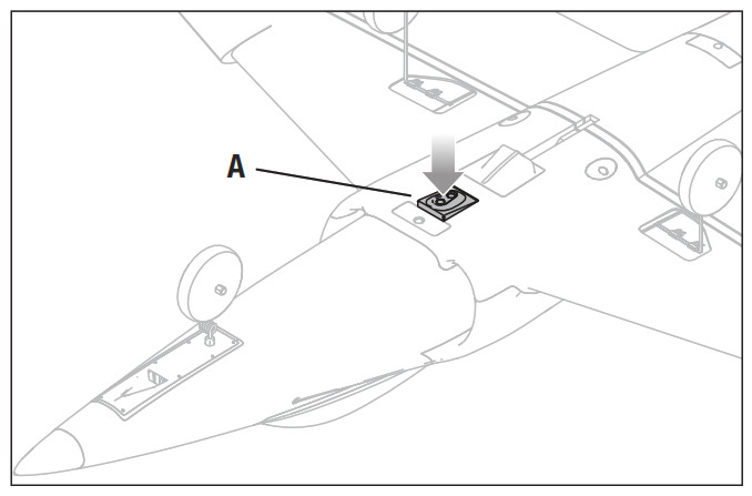
Installation of the LAS module
- Rotate the aircraft to access the bottom of the fuselage.
- Press the factory-installed plug (A) to release it. Then removed it from the LAS pocket. Save the plug for flights without LAS module.
- Feed the LAS connector through the channel in the base of the LAS pocket.
- Align the LAS module with the wires facing the back of the aircraft.Place the LAS module into the pocket and press it to secure it into place with a click.
- Place the aircraft on its landing gear and connect LAS connector to Channel 7 on the flight controller. For correct polarity of the plug ensure that the orange (not brown) signal wire (B) is facing towards the front of the aircraft when plugged into the flight controller.
Landing with LASReduce throttle, keep the wings level and slowly reduce the altitude of the aircraft. When the aircraft’s landing approach reaches an altitude of roughly 1m the LAS will level off the aircraft, manage the throttle, and then flare the aircraft for a touchdown.IMPORTANT: LAS is functional for all SAFE flight modes except for Experienced Mode. When the flight mode is switched to Experienced mode the LAS is deactivated and the pilot will have zero assistance on landing, a traditional manual landing of the aircraft is necessary.IMPORTANT: Installation of the LAS module is not auto land. The aircraft must be guided and aligned with the landing strip for landing.TIP: If the speed of the aircraft is too fast for landing or above 20% throttle setting, LAS is not effective.TIP: If the Aircraft’s landing approach is too low and fast, LAS will not flare.


Service and Repairs
NOTICE: After any impact or replacement, always ensure the receiver and flight controller are secure in the fuselage. If you replace the receiver or flight controller, install the new receiver in the same orientation and manner as the original receiver or damage may result.Repairs to the wings and fuselage of this aircraft can be made easily using virtually any adhesive (hot glue, regular CA (cyanoacrylate adhesive), epoxy, etc).When parts are not repairable, see the Replacement Parts List for ordering by item number. For a listing of all replacement and optional parts, refer to the list at the back of this manual.

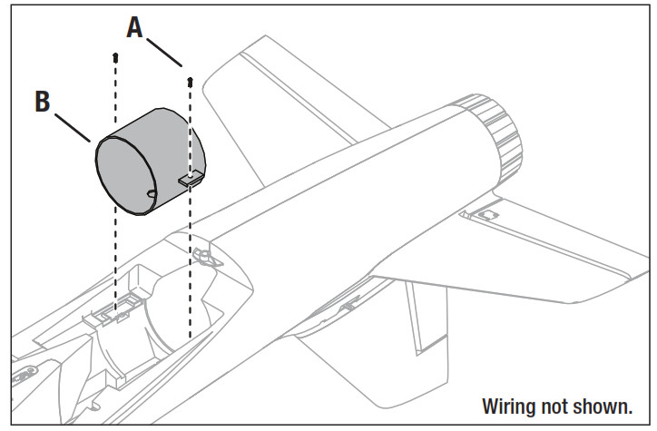
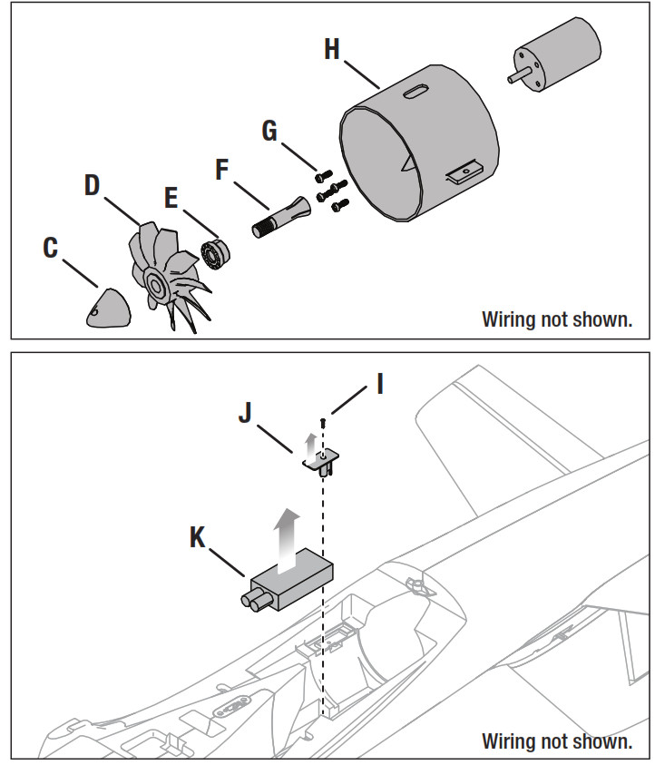
Power Components ServiceDisassembly
- Remove the four screws and carefully remove the wing.
- Remove the two screws (A) from the fan unit mounting tabs.
- Pull the fan unit (B) out of the fuselage and disconnect the motor leads from the ESC.
- Remove the spinner (C) from the rotor by using a hex wrench inserted through the spinner holes and turning the spinner from the motor shaft adapter.
- Remove the rotor (D), rotor backplate (E) and motor shaft adapter (F).
- Remove the four screws (G) to remove the motor from the fan shroud (H).
- Remove the screw (I) and plastic ESC clip (J) .
- Disconnect the throttle lead from the receiver and pull the ESC (K) from the fuselage, taking note of the routing of the power and throttle leads through the fuselage.
AssemblyAssemble in reverse order.• Assemble in reverse order.• Correctly align and connect the motor wire colors with the ESC wires.• Ensure the ESC is installed correctly and secured to the fuselage using clip and screw.• Ensure the front of the rotor is installed facing the nose of the aircraft.• Use a hex wrench to tighten the spinner on the rotor and collet.• Ensure the spinner is fully connected for safe operation.• Ensure no wiring is pinched by any of the power components.• Correctly align and install wing to fuselage using 4 wing screws.
Replacement Parts
| Part # | Description |
| EFLO1551 | Fuselage, Painted: Habu STS |
| EFLO1552 | Wing, Painted: Habu STS |
| EFLO1553 | Horizontal Stabilizer: Habu STS |
| EFLO1554 | Landing Gear Set: Habu STS |
| EFLO1555 | Hatch: Habu STS |
| EFLO1556 | Decal Sheet: Habu STS |
| EFLO1557 | Pushrod Set,Servo Cvrs:Habu STS |
| EFLO1558 | 70mm EDF Unit w/Motor: Habu STS |
| EFLO1559 | 70mm Ducted Fan: Habu STS |
| EFLO1560 | Tail Cone: Habu STS |
| EFLO1561 | Hands-Free Connector: Habu STS |
| EFL01562 | Vertical Fin Assembly: Habu STS |
| EFLO1563 | Control Horn Set: Habu STS |
| SPMXAE0070 | 70-Amp 3S/4S ESC w/Telemetry |
| SPM4650C | DSMX SRXL2 RX w/Connector |
| SINA3230B | Flight Controller: Habu STS |
| SPMR1010 | DXS Transmitter Only |
| SPMSA381 | 9g Mini Servo: 400mm Lead |
| SPMSA3811 | Servo Arms, Gears SA381 Servo |
| SPMSA382 | 13g Metal Gear Servo, 240mm Lead |
| SPMSA3821 | Servo Arms, Gears SA382 Servo |
| SPMX40003S30 | 4000mAh 3S 11.1V Smart 30C; IC3 |
| SPMXAM1100 | BL Motor 2847-3200: Habu STS |
| SPMXC1020 | S120 USB-C Smart Charger, 1x2OW |
Recommended Parts
| Part #SPMR1010 | Description |
| DXS Transmitter Only | |
| SPMR8000 | DX8 Transmitter Only MD2 |
| SPMR9910 | DX9 Black Transmitter Only MD2 |
| SPMX40003S30 | 4000mah 3S 11.1V Smart 30C; IC3 |
| SPMXC1010 | Smart S2100 AC Charger, 2X100W |
Optional Parts
| Part # | Description |
| SPM6716 | Spektrum DSMR Transmitter Case |
| SPM6722 | Spektrum Single Aircraft TX Case |
| SPMA3180 | Landing Assist Sensor (LAS) |
| SPMR8000 | DX8 Transmitter Only MD2 |
| SPMX32004S30 | 3200mAh 4S 14.8V Smart 30C: IC3 |
| SPNX40004S30 | 4000mAh 4S 14.8V Smart 30C: IC3 |
| SPMXBC100 | SMART Battery & Servo Tester |
| SPMXC1010 | Smart S2100 AC Charger, 2X1DOW |
| SR/K10201 | 30A 540W Power Supply |
| SR/K10202 | 16A 380W Power Supply |
| SPMXC1050 | Smart S1500 DC Charger, 1 x500W |
| SPMXC1070 | Smart S150 AC/DC Charger, 1 x5OW |
AMA National Model Aircraft Safety Code
Effective January 1, 2014A. GENERALA model aircraft is a non-human-carrying aircraft capable of sustained flight in the atmosphere. It may not exceed limitations of this code and is intended exclusively for sport, recreation, education and/or competition. All model flights must be conducted in accordance with this safety code and any additional rules specific to the flying site.
- Model aircraft will not be flown:(a) In a careless or reckless manner.(b) At a location where model aircraft activities are prohibited.
- M odel aircraft pilots will:(a) Yield the right of way to all man carrying aircraft.(b) See and avoid all aircraft and a spotter must be used when appropriate.(AMA Document #540-D.)(c) Not fly higher than approximately 400 feet above ground level within three (3) miles of an airport, without notifying the airport operator.(d) Not interfere with operations and traffic patterns at any airport, heliport or seaplane base except where there is a mixed use agreement.(e) Not exceed a takeoff weight, including fuel, of 55 pounds unless in compliance with the AMA Large Model Aircraft program. (AMA Document 520-A.)(f) Ensure the aircraft is identified with the name and address or AMA number of the owner on the inside or affixed to the outside of the model aircraft. (This does not apply to model aircraft flown indoors).(g) Not operate aircraft with metal-blade propellers or with gaseous boosts except for helicopters operated under the provisions of AMA Document #555.(h) Not operate model aircraft while under the influence of alcohol or while using any drug which could adversely affect the pilot’s ability to safely control the model.(i) Not operate model aircraft carrying pyrotechnic devices which explode or burn, or any device which propels a projectile or drops any object that creates a hazard to persons or property.Exceptions:• Free Flight fuses or devices that burn producing smoke and are securely attached to the model aircraft during flight.• Rocket motors (using solid propellant) up to a G-series size may be used provided they remain attached to the model during flight. Model rockets may be flown in accordance with the National Model Rocketry Safety Code but may not be launched from model aircraft.• Officially designated AMA Air Show Teams (AST) are authorized to use devices and practices as defined within the Team AMA Program Document (AMA Document #718).(j) Not operate a turbine-powered aircraft, unless in compliance with the AMA turbine regulations. (AMA Document #510-A).
- Model aircraft will not be flown in AMA sanctioned events, air shows or model demonstrations unless:(a) The aircraft, control system and pilot skills have successfully demonstrated all maneuvers intended or anticipated prior to the specific event.(b) An inexperienced pilot is assisted by an experienced pilot.
- When and where required by rule, helmets must be properly worn and fastened. They must be OSHA, DOT, ANSI, SNELL or NOCSAE approved or comply with comparable standards.
B. RADIO CONTROL
- All pilots shall avoid flying directly over unprotected people, vessels, vehicles or structures and shall avoid endangerment of life and property of others.
- A successful radio equipment ground-range check in accordance with manufacturer’s recommendations will be completed before the first flight of a new or repaired model aircraft.
- At all flying sites a safety line(s) must be established in front of which all flying takes place (AMA Document #706.)(a) Only personnel associated with flying the model aircraft are allowed at or in front of the safety line.(b) At air shows or demonstrations, a straight safety line must be established.(c) An area away from the safety line must be maintained for spectators.(d) Intentional flying behind the safety line is prohibited.
- RC model aircraft must use the radio-control frequencies currently allowed by the Federal Communications Commission (FCC). Only individuals properly licensed by the FCC are authorized to operate equipment on Amateur Band frequencies.
- RC model aircraft will not operate within three (3) miles of any pre-existing flying site without a frequency-management agreement (AMA Documents#922 and #923.)
- With the exception of events flown under official AMA Competition Regulations, excluding takeoff and landing, no powered model may be flown outdoors closer than 25 feet to any individual, except for the pilot and the pilot’s helper(s) located at the flight line.
- Under no circumstances may a pilot or other person touch a model aircraft in flight while it is still under power, except to divert it from striking an individual.
- RC night flying requires a lighting system providing the pilot with a clear view of the model’s attitude and orientation at all times. Hand-held illumination systems are inadequate for night flying operations.
- The pilot of a RC model aircraft shall:(a) Maintain control during the entire flight, maintaining visual contact without enhancement other than by corrective lenses prescribed for the pilot.(b) Fly using the assistance of a camera or First-Person View (FPV) only in accordance with the procedures outlined in AMA Document #550.(c) Fly using the assistance of autopilot or stabilization system only in accordance with the procedures outlined in AMA Document #560.
Please see your local or regional modeling association’s guidelines for proper, safe operation of your model aircraft.
Limited Warranty
What this Warranty CoversHorizon Hobby, LLC, (Horizon) warrants to the original purchaser that the product purchased (the “Product”) will be free from defects in materials and workmanship at the date of purchase.What is Not CoveredThis warranty is not transferable and does not cover (i) cosmetic damage, (ii) damage due to acts of God, accident, misuse, abuse, negligence, commercial use, or due to improper use, installation, operation or maintenance, (iii) modification of or to any part of the Product, (iv) attempted service by anyone other than a Horizon Hobby authorized service center, (v) Product not purchased from an authorized Horizon dealer, (vi) Product not compliant with applicable technical regulations, or (vii) use that violates any applicable laws, rules, or regulations.OTHER THAN THE EXPRESS WARRANTY ABOVE, HORIZON MAKES NO OTHER WARRANTY OR REPRESENTATION, AND HEREBY DISCLAIMS ANY AND ALL IMPLIED WARRANTIES, INCLUDING, WITHOUT LIMITATION, THE IMPLIED WARRANTIES OF NON- INFRINGEMENT, MERCHANTABILITY, AND FITNESS FOR A PARTICULAR PURPOSE. THE PURCHASER ACKNOWLEDGES THAT THEY ALONE HAVE DETERMINED THAT THE PRODUCT WILL SUITABLY MEET THE REQUIREMENTS OF THE PURCHASER’S INTENDED USE.
Purchaser’s RemedyHorizon’s sole obligation and purchaser’s sole and exclusive remedy shall be that Horizon will, at its option, either (i) service, or (ii) replace, any Product determined by Horizon to be defective. Horizon reserves the right to inspect any and all Product(s) involved in a warranty claim. Service or replacement decisions are at the sole discretion of Horizon. Proof of purchase is required for all warranty claims.SERVICE OR REPLACEMENT AS PROVIDED UNDER THIS WARRANTY IS THE PURCHASER’S SOLE AND EXCLUSIVE REMEDY.Limitation of LiabilityHORIZON SHALL NOT BE LIABLE FOR SPECIAL, INDIRECT, INCIDENTAL OR CONSEQUENTIAL DAMAGES, LOSS OF PROFITS OR PRODUCTION OR COMMERCIAL LOSS IN ANY WAY, REGARDLESS OF WHETHER SUCH CLAIM IS BASED IN CONTRACT, WARRANTY, TORT, NEGLIGENCE, STRICT LIABILITY OR ANY OTHER THEORY OF LIABILITY, EVEN IF HORIZON HAS BEEN ADVISED OF THE POSSIBILITY OF SUCH DAMAGES. Further, in no event shall the liability of Horizon exceed the individual price of the Product on which liability is asserted. As Horizon has no control over use, setup, final assembly, modification or misuse, no liability shall be assumed nor accepted for any resulting damage or injury. By the act of use, setup or assembly, the user accepts all resulting liability. If you as the purchaser or user are not prepared to accept the liability associated with the use of the Product, purchaser is advised to return the Product immediately in new and unused condition to the place of purchase.LawThese terms are governed by Illinois law (without regard to conflict of law principals). This warranty gives you specific legal rights, and you may also have other rights which vary from state to state. Horizon reserves the right to change or modify this warranty at any time without notice.WARRANTY SERVICESQuestions, Assistance, and ServicesYour local hobby store and/or place of purchase cannot provide warranty support or service. Once assembly, setup or use of the Product has been started, you must contact your local distributor or Horizon directly. This will enable Horizon to better answer your questions and service you in the event that you may need any assistance. For questions or assistance, please visit our website at www.horizonhobby.com, submit a Product Support Inquiry, or call the toll-free telephone number referenced in the Warranty and Service Contact Information section to speak with a Product Support representative.
Inspection or ServicesIf this Product needs to be inspected or serviced and is compliant in the country you live and use the Product in, please use the Horizon Online Service Request submission process found on our website or call Horizon to obtain a Return Merchandise Authorization (RMA) number. Pack the Product securely using a shipping carton. Please note that original boxes may be included, but are not designed to withstand the rigors of shipping without additional protection. Ship via a carrier that provides tracking and insurance for lost or damaged parcels, as Horizon is not responsible for merchandise until it arrives and is accepted at our facility. An Online Service Request is available at http://www.horizonhobby.com/content/service-center_render-service-center. If you do not have internet access, please contact Horizon Product Support to obtain a RMA number along with instructions for submitting your product for service. When calling Horizon, you will be asked to provide your complete name, street address, email address, and phone number where you can be reached during business hours. When sending product into Horizon, please include your RMA number, a list of the included items, and a brief summary of the problem. A copy of your original sales receipt must be included for warranty consideration. Be sure your name, address, and RMA number are clearly written on the outside of the shipping carton.
NOTICE: Do not ship LiPo batteries to Horizon. If you have any issue with a LiPo battery, please contact the appropriate Horizon Product Support office.
Warranty RequirementsFor Warranty consideration, you must include your original sales receipt verifying the proof-of-purchase date. Provided warranty conditions have been met, your Product will be serviced or replaced free of charge. Service or replacement decisions are at the sole discretion of Horizon.
Non-Warranty ServiceShould your service not be covered by warranty, service will be completed and payment will be required without notification or estimate of the expense unless the expense exceeds 50% of the retail purchase cost. By submitting the item for service you are agreeing to payment of the service without notification. Service estimates are available upon request. You must include this request with your item submitted for service. Non-warranty service estimates will be billed a minimum of ½ hour of labor. In addition you will be billed for return freight. Horizon accepts money orders and cashier’s checks, as well as Visa, MasterCard, American Express, and Discover cards. By submitting any item to Horizon for service, you are agreeing to Horizon’s Terms and Conditions found on our website http://www.horizonhobby.com/content/service-center_render-service-center.
ATTENTION: Horizon service is limited to Product compliant in the country of use and ownership. If received, a non-compliant Product will not be serviced. Further, the sender will be responsible for arranging return shipment of the un-serviced Product, through a carrier of the sender’s choice and at the sender’s expense. Horizon will hold non-compliant Product for a period of 60 days from notification, after which it will be discarded.
Warranty and Service Contact Information
| Country of Purchase | Horizon Hobby | Contact Information | Address |
| United States of America | Horizon Service Center (Repairs and Repair Requests) | servicecenter.horizonhobby.con-RequestForm/ | 2904 Research Rd Champaign, IL 61822 |
| Horizon Product Support (Product Technical Assistance) | [email protected] 877-504-0233 | ||
| Sales | [email protected] | ||
| 800-338-4639 | |||
| European Union | Horizon Technischer Service | [email protected] | Hanskampdng 9D 22885 Barsbiittel, Germany |
| Sales: Horizon Hobby GmbH | +49 (0) 4121 2655 100 |
FCC Information
Contains FCC ID: BRWSRLRR2 and FCC ID: BRWKATY1TThis device complies with part 15 of the FCC rules. Operation is subject to the following two conditions: (1) This device may not cause harmful interference, and (2) this device must accept any interference received, including interference that may cause undesired operation.CAUTION: Changes or modifications not expressly approved by the party responsible for compliance could void the user’s authority to operate the equipment. This product contains a radio transmitter with wireless technology which has been tested and found to be compliant with the applicableregulations governing a radio transmitter in the 2.400GHz to 2.4835GHz frequency range.
Supplier’s Declaration of ConformityEFL Habu STS RTF and PNP (EFL01500 and EFL01575)This device complies with part 15 of the FCC Rules. Operation is subject to the following two conditions: (1) This device may not cause harmful interference, and (2) this device must accept any interference received, including interference that may cause undesired operation.CAUTION: changes or modifications not expressly approved by the party responsible for compliance could void the user’s authority to operate the equipment.NOTE: This equipment has been tested and found to comply with the limits for a Class B digital device, pursuant to part 15 of the FCC Rules. These limits are designed to provide reasonable protection against harmful interference in a residential installation. This equipment generates, uses and can radiate radiofrequency energy and, if not installed and used in accordance with the instructions, may cause harmful interference to radio communications. However, there is no guarantee that interference will not occur in a particular installation. If this equipment does cause harmful interference to radio or television reception, which can be determined by turning the equipment off and on, the user is encouraged to try to correct the interference by one or more of the following measures:• Reorient or relocate the receiving antenna.• Increase the separation between the equipment and receiver.• Connect the equipment into an outlet on a circuit different from that to which the receiver is connected.• Consult the dealer or an experienced radio/TV technician for help.Horizon Hobby, LLC2904 Research Rd., Champaign, IL 61822Email: [email protected]Web: HorizonHobby.com
IC Information
Contains IC: 6157A-SRLRR2 and IC: 6157A-KATY1TCAN ICES-3 (B)/NMB-3(B)This device complies with Industry Canada licence-exempt RSS standard(s).Operation is subject to the following two conditions:(1) this device may not cause interference, and (2) this device must accept any interference, including interference that may cause undesired operation of the device.
Compliance Information for the European Union
 EU Compliance Statement:EFL Habu STS RTF (EFL01500)Horizon Hobby, LLC hereby declares that this product is in compliance with the essential requirements and other relevant provisions of the RED and EMC Directives.A copy of the EU Declaration of Conformity is available online at: http://www.horizonhobby.com/content/support-render-compliance.
Frequency Band: 2404-2476 MHzMax EIRP: 2.96dBmTransmitter Max EIRP: 20dBm
EFL Habu STS PNP (EFL01575)Horizon Hobby, LLC hereby declares that this product is in compliance with the essential requirements and other relevant provisions of the EMC Directives.A copy of the EU Declaration of Conformity is available online at: http://www.horizonhobby.com/content/support-render-compliance.
Instructions for disposal of WEEE by users in the European Union
 This product must not be disposed of with other waste. Instead, it is the user’s responsibility to dispose of their waste equipment by handing it over to a designated collection point for the recycling of waste electrical and electronic equipment. The separate collection and recycling of your waste equipment at the time of disposal will help to conserve natural resources and ensure that it is recycled in a manner that protects human health and the environment. For more information about where you can drop off your waste equipment for recycling, please contact your local city office, your household waste disposal service, or where you purchased the product.

©2020 Horizon Hobby, LLC.E-flite, Avian, Plug-N-Play, Bind-N-Fly, BNF, the BNF logo, DSM, DSM2, DSMX, SRXL2, Spektrum AirWare, EC5, IC5, AS3X, SAFE, the SAFE logo, ModelMatch, and the Horizon Hobby logo are trademarks or registered trademarks of Horizon Hobby, LLC.The Spektrum trademark is used with permission of Bachmann Industries, Inc.Futaba is a registered trademark of Futaba Denshi Kogyo Kabushiki Kaisha Corporation of Japan.All other trademarks, service marks and logos are property of their respective owners. US 8,672,726. US 9,056,667. US 9,753,457. US 10,078,329. US 9,930,567. US 10,419,970 .CN201721563463.4. Other patents pending.http://www.horizonhobby.com/
References
RC Airplanes and Helicopters, RC Cars and Trucks, RC Boats, RC Radios | Horizon Hobby
RC Cars, RC Trucks, RC Airplanes, Model Trains, and Slot Cars at Tower Hobbies
Horizon Hobby Compliance Information
Ferngesteuerte Flugmodelle, Autos, Trucks, Hubschrauber, Boote und Fernsteuerungen | Horizon Hobby
Spektrum RC Transmitters and RC Electronics | Spektrum
Academy of Model Aeronautics
RC Airplanes and Helicopters, RC Cars and Trucks, RC Boats, RC Radios | Horizon Hobby
[xyz-ips snippet=”download-snippet”]