
![]()
![]()
600mmInstruction Manual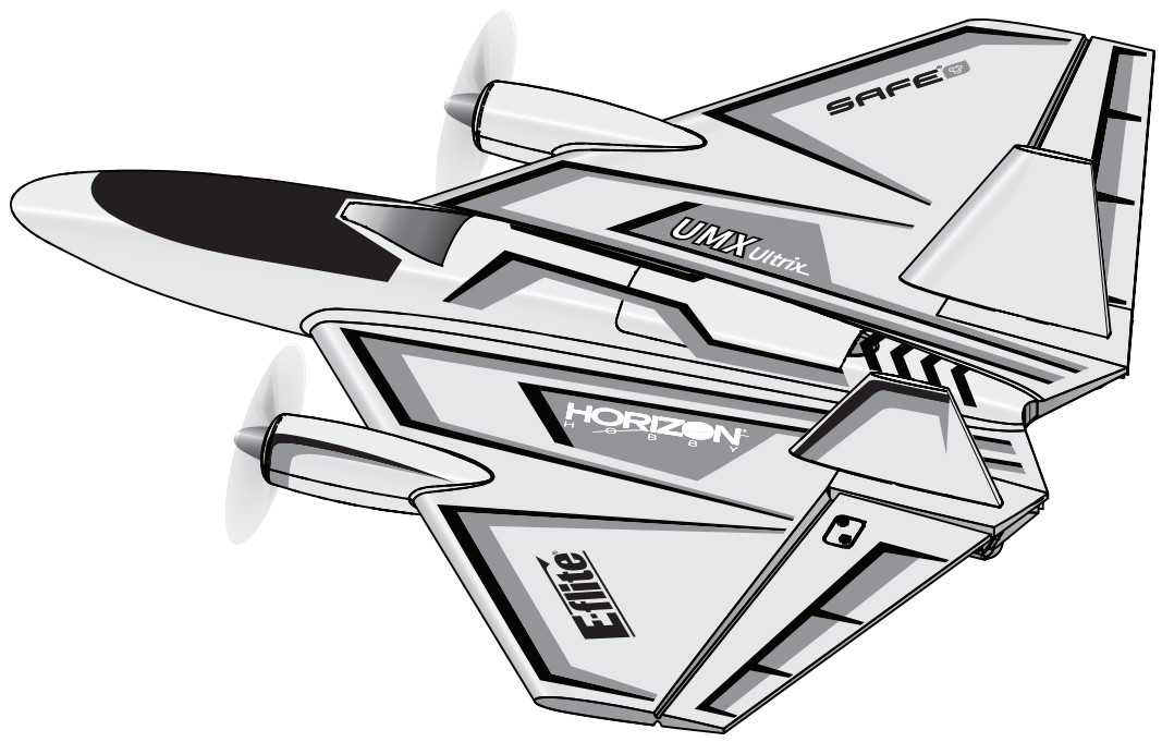
NOTICEAll instructions, warranties, and other collateral documents are subject to change at the sole discretion of Horizon Hobby, LLC. For up-to-date product literature, visit orizonhobby.com or towerhobbies.com and click on the support or resources tab for this product.
MEANING OF SPECIAL LANGUAGE
The following terms are used throughout the product literature to indicate various levels of potential harm when operating this product:![]() WARNING: Procedures, which if not properly followed, create the probability of property damage, collateral damage, and serious injury OR create a high probability of superficial injury.CAUTION: Procedures, which if not properly followed, create the probability of physical property damage AND a possibility of serious injury.NOTICE: Procedures, which if not properly followed, create a possibility of physical property damage AND little or no possibility of injury.WARNING: Read the ENTIRE instruction manual to become familiar with the features of the product before operating. Failure to operate the product correctly can result in damage to the product, personal property and cause serious injury.This is a sophisticated hobby product. It must be operated with caution and common sense and requires some basic mechanical ability. Failure to operate this Product in a safe and responsible manner could result in injury or damage to the product or other property. This product is not intended for use by children without direct adult supervision. Donot use incompatible components or alter this product in any way outside of the instructions provided by Horizon Hobby, LLC. This manual contains instructions for safety, operation, and maintenance. It is essential to read and follow all the instructions and warnings in the manual, prior to assembly, setup or use, in order to operate correctly and avoid damage or serious injury.
WARNING: Procedures, which if not properly followed, create the probability of property damage, collateral damage, and serious injury OR create a high probability of superficial injury.CAUTION: Procedures, which if not properly followed, create the probability of physical property damage AND a possibility of serious injury.NOTICE: Procedures, which if not properly followed, create a possibility of physical property damage AND little or no possibility of injury.WARNING: Read the ENTIRE instruction manual to become familiar with the features of the product before operating. Failure to operate the product correctly can result in damage to the product, personal property and cause serious injury.This is a sophisticated hobby product. It must be operated with caution and common sense and requires some basic mechanical ability. Failure to operate this Product in a safe and responsible manner could result in injury or damage to the product or other property. This product is not intended for use by children without direct adult supervision. Donot use incompatible components or alter this product in any way outside of the instructions provided by Horizon Hobby, LLC. This manual contains instructions for safety, operation, and maintenance. It is essential to read and follow all the instructions and warnings in the manual, prior to assembly, setup or use, in order to operate correctly and avoid damage or serious injury.
Age Recommendation: Not for children under 14 years. This is not a toy.
Safety Precautions and Warnings
As the user of this product, you are solely responsible for operating in a manner that does not endanger yourself and others or result in damage to the product or the property of others.
- Always keep a safe distance in all directions around your model to avoid collisions or injury. This model is controlled by a radio signal subject to interference from many sources outside your control. Interference can cause momentary loss of control.
- Always operate your model in open spaces away from full-size vehicles, traffic, and people.
- Always carefully follow the directions and warnings for this and any optional support equipment (chargers, rechargeable battery packs, etc.).
- Always keep all chemicals, small parts, and anything electrical out of the reach of children.
- Always avoid water exposure to all equipment not specifically designed and protected for this purpose. Moisture causes damage to electronics.
- Never place any portion of the model in your mouth as it could cause serious injury or even death.
- Never operate your model with low transmitter batteries.
- Always keep aircraft in sight and under control.
- Always use fully charged batteries.
- Always keep the transmitter powered on while the aircraft is powered.
- Always remove batteries before disassembly.
- Always keep moving parts clean.
- Always keep parts dry.
- Always let parts cool after use before touching.
- Always remove batteries after use.
- Always ensure the failsafe is properly set before flying.
- Always engage throttle cut before approaching the aircraft.
- Never operate aircraft with damaged wiring.
- Never touch moving parts.
![]() WARNING AGAINST COUNTERFEIT PRODUCTS: If you ever need to replace your Spektrum receiver found in a Horizon Hobby product, always purchase from Horizon Hobby, LLC or a Horizon Hobby authorized dealer to ensure authentic high-quality Spektrum product. Horizon Hobby, LLC disclaims all support and warranty with regards to, but not limited to, compatibility and performance of counterfeit products or products claiming compatibility with DSM or Spektrum technology.
WARNING AGAINST COUNTERFEIT PRODUCTS: If you ever need to replace your Spektrum receiver found in a Horizon Hobby product, always purchase from Horizon Hobby, LLC or a Horizon Hobby authorized dealer to ensure authentic high-quality Spektrum product. Horizon Hobby, LLC disclaims all support and warranty with regards to, but not limited to, compatibility and performance of counterfeit products or products claiming compatibility with DSM or Spektrum technology.
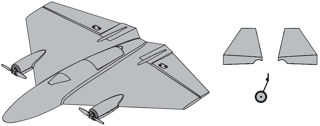
Box Contents
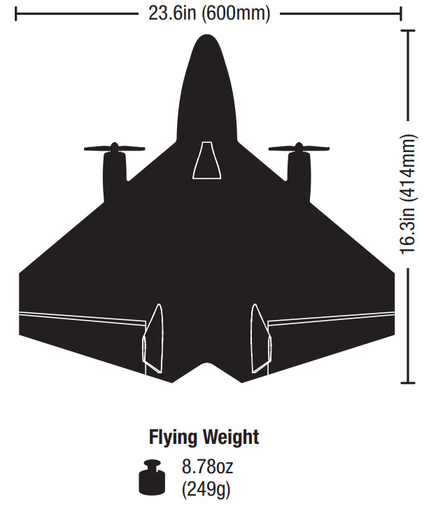
Specifications
Components
Installed
| Motors | (2) 1206-3900Kv Brushless In-Runner 12-pole (SPMXAM2000) |
| Receiver | Spektrum— AS3X/SAFE Receiver iSPMA3255) |
| Servo | Elevon: Q) Spektrum SPMSH2040LIN |
Required to Complete
| Transmitter | Full range 6-channel 2.4GHz with Speldrum DSMX° technology with adjustable Dual Rates. |
| Battery | 11.1V 3S 85OrnAh – w/IC2″ connector (SPMX8503S30) |
| Battery Charger | 3-cell Li-Po battery balancing charger |
Preflight Checklist
| 1 | Remove and inspect contents. |
| 2 | Read the instruction manual thoroughly. |
| 3 | Charge the flight battery. |
| 4 | Program your transmitter. |
| 5 | Install the fully charged flight battery in the aircraft |
| 6 | Check the center of gravity (CG). |
| 7 | Bind the aircraft to your transmitter. |
| 8 | Make sure all linkages move freely. |
| 9 | Perform the control direction test. |
| 10 | Adjust the flight controls and transmitter as needed. |
| 11 | Perform a radio system range test. |
| 12 | Find a safe open area to fly. |
| 13 | Plan flight for flying field conditions. |
Transmitter Setup
IMPORTANT: After you set up your model, always rebind the transmitter and receiver to set the desired failsafe positions.If your transmitter allows it, enable the throttle cut feature. Always engage throttle cut before approaching the aircraft.IMPORTANT: The Ultrix DOES NOT need elevon mixing. The elevon mixing is handled in the receiver.Dual RatesFlight modes and dual rates/expo should be on the same switch.A low rate is recommended for the initial flights.NOTICE: To ensure AS3X® technology functions properly do not lower rate values below 50%.ExpoAfter your initial flights, you may adjust the expo value to better suit your flying style.Control For Optional LightsThe optional LEDs are controlled from channel 6. In the channel input menu, set channel 6 (Aux1) to a momentary witch (I). In the Servo Setup menu, reverse channel 6 (Aux1). The LEDs will change to the next light pattern each time channel 6 is cycled.
| Computerized Transmitbu Setup | |
| Start all transmitter grammar with a blank ICRO model (do a model reset), then name the model. | |
| Mode switch | Assign Ch5 to switch B (Channel input config) |
| Servo Setup | Normal Ch 1-5. Reverse Ch 6 |
| Travel 100% | |
| Rates and Expo (ail. ele. rud) | Switch of your choice. we recommend switch B |
| (Pos 0) Rates | 100% |
| (POs 0) Expo | 0% |
| (Pos 1) Pate | 70% |
| (Pos 1) Expo | 30% |
| (Pos 2) Pate | 100% |
| (Pos 2) Expo | 40% |
| Timer | 5-8 minutes |
| Throttle Cut | Assign to Switch H (-130%) |
With both Ch 5 and Rates/Expo assigned to the same switch, there are three flight modes.(Pos 0) SAFE(Pos 1) AS3X low rate(Pos 2) AS3X high rate
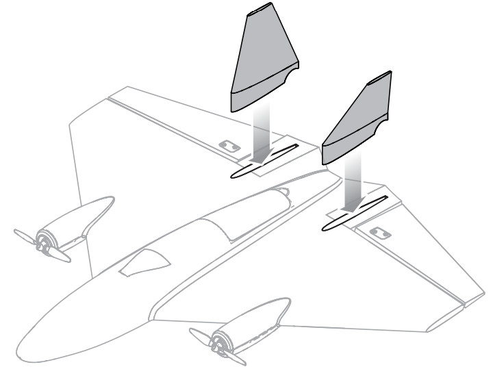
Install the Vertical Stabilizers
Press the vertical stabilizers into position.
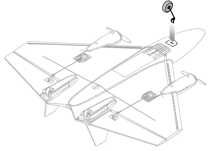
Optional Nose Gear
Invert the aircraft and press the optional nose gear into the slot on the bottom of the fuselage.
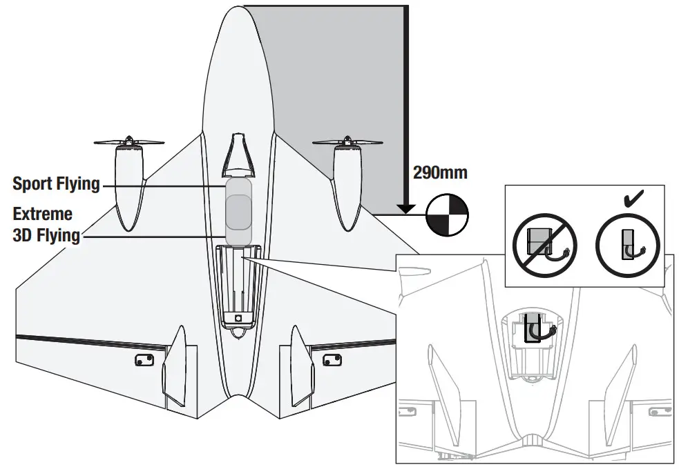
Battery Placement and Center of Gravity (CG)
The CG location is 290mm back from the nose, which was determined with the recommended battery at the front of the battery tray.-Sport Flying Battery Location: Install the battery in the front of the battery compartment.-Extreme 3D Location: Install the battery so that the back edge of the battery is aligned with the front edge of the battery hatch opening.
Transmitter and Receiver Binding
| Binding Procedure |
| 1. Refer to your transmitter manual for instruction on binding the transmitter to a receiver. |
| 2. Ensure the flight battery is not corrected to the aircraft. |
| 3. Depending on your transmitter, either power off the transmitter or ensure the RF signal is off. |
| 4. Connect the flight battery to the Aircraft. The LEDs will begin flashing fast, the LED will flashing blue and red indicating the receiver is in the binding mode. |
| 5. Make sure the transmitter controls are at neutral and the throttle and throttle trim are ii the low position. |
| 6. Place the transmitter in bind mode. Refer to your transmitter manual for tindrig instructions. |
| 7. After 5-10 seconds. the receiver will connect and the motor will arm. if you encounter problems refer to the Troubleshooting Guide at the bad( of the manual. |
For subsequent flights, power on the transmitter for 5 seconds before connecting the flight battery.
| LED Indicator on Receiver | |
| Waiting to Bind | Fast Blue flashing and fast red flashing |
| Connected, throttle not at zero | Red and Blue Solid |
| SAFE Mode | Blue Solid |
| AS3X Mode | Red Solid |
| Low Voltage Cutoff | Red Flashing |
Arming the ESC also occurs after binding as previously described, but the subsequent connection of a flight battery requires the steps below.
Arming the ESC
- Lower throttle and throttle trim to lowest settings. Power on the transmitter then wait 5 seconds

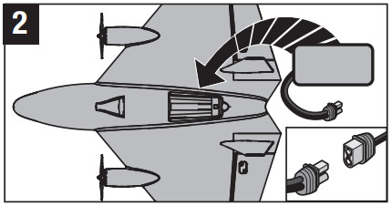
- Install the flight battery and connect it to the ESC. Slide battery to nose
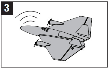
- Keep the plane immobile, upright, and away from the wind for 5 seconds. A series of tones indicates the aircraft is armed and ready.

Low Voltage Cutoff (LVC)
When a Li-Po battery is discharged below 3V per cell, it will not hold a charge. The aircraft’s ESC protects the flight battery from over-discharge using Low Voltage Cutoff (LVC). Before the battery charge decreases too much, LVC removes power supplied to the motor. Power to the motor quickly decreases and increases, showing that some battery power is reserved for flight control and safe landing.When the motor power pulses, land the aircraft immediately and recharge the flight battery. Disconnect and remove the Li-Po battery from the aircraft after use to prevent trickle discharge. During storage, make sure the battery charge does not fall below 3V per cell.TIP: Due to the quiet nature of the aircraft, you may not hear the pulsing of the motor.For your first flights, set your transmitter timer or a stopwatch to 3 minutes. Adjust your timer for longer or shorter flights once you have flown the aircraft. Flights of 4 minutes or more are achievable if using proper throttle management.NOTICE: Repeated flying to LVC will damage the battery.
Control Centering
Before the first flights, or in the event of an accident, make sure the flight control surfaces are centered. Adjust the linkages mechanically if the control surfaces are not centered. The use of the transmitter sub-trims may not correctly center the aircraft control surfaces due to the mechanical limits of linear servos.
- Ensure AS3X is OFF.
- Make sure the control surfaces are neutral when the transmitter controls and trims are centered. The transmitter sub-trim must always be set to zero.
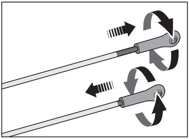
- When needed, adjust the linkage. Turn the ball link on the linkage to change the length between the servo arm and the control horn until the elevon is straight.
Centering Controls After First FlightsFor best performance with AS3X, it is important that excessive trim is not used. Do not trim the aircraft while SAFE Select is active. Always trim the aircraft in AS3X mode. If the model requires excessive transmitter trim (4 or more clicks of trim per channel), return the transmitter trim to zero and adjust the linkages mechanically so that the control surfaces are in the flight trimmed position.
Control Direction Test
Properly bind your aircraft and transmitter before doing these tests. Verify the linkages move freely. Switch ON the transmitter and connect the battery. Use the transmitter to operate the aileron and elevator controls. View the aircraft from the rear when checking the control directions.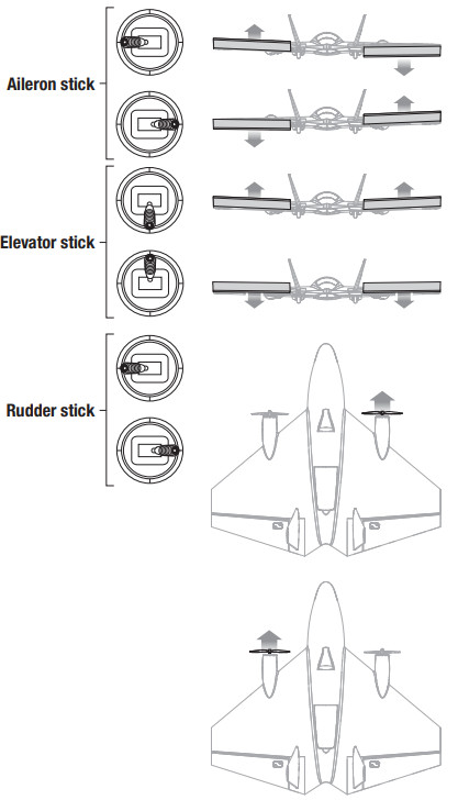 Ailerons
- Move the aileron stick to the left. The right elevon should move down and the left elevon up, which will cause the aircraft to bank left in flight.
- Move the aileron stick to the right. The right elevon should move up and the left elevon down, which will cause the aircraft to bank right in flight.Elevators
- Pull the elevator stick back. The elevons should move up, which will cause the aircraft to pitch up in flight.
- Push the elevator stick forward. The elevons should move down, which will cause the aircraft to pitch down in flight.Rudder/ Differential Thrust
- Move the rudder stick to the left. The right motor will accelerate, which will cause the aircraft to yaw left in flight.
- Move the rudder stick to the right. The left motor will accelerate, which will cause the aircraft to yaw right in flight.Tip: The motors will not accelerate with rudder input when the throttle is in the OFF position.
Smart Technology Telemetry
This aircraft includes Spektrum Smart Technology in the receiver, which can provide telemetry information like battery voltage. To take advantage of Smart Technology, you will need a compatible transmitter. A firmware update for your transmitter may be required.To View Smart Telemetry:
- Begin with the transmitter bound to the receiver
- Power on the transmitter.
- Power on the aircraft.
- The Smart Logo appears under the battery logo on the home page. A signal bar appears in the top left corner of the screen.
- Scroll past the servo monitor to view Smart technology screens.
For more information about compatible transmitters, firmware updates, and how to use the Smart Technology on your transmitter, visit www.SpektrumRC.com.
SAFE® Technology
The Ultrix has two flight modes on Channel 5, SAFE and AS3X.When flying in SAFE mode, the aircraft will return to level flight any time the aileron and elevator controls are neutral. Applying aileron or elevator control will cause the airplane to the bank, climb, or dive. The amount the stick is moved will determine the attitude the airplane flies. Holding full control will push the aircraft to the predetermined bank and pitch limits, but it will not go past those angles.When flying in a SAFE ode, it is normal to hold the control stick deflected with moderate aileron input when flying through a turn. To fly smoothly with SAFE, avoid making frequent control changes and don’t attempt to correct for minor deviations. Holding deliberate control inputs will command the aircraft to fly at a specific angle, and the model will make all corrections to maintain that flight attitude.Return the elevator and aileron controls to neutral before switching from SAFE mode to AS3X mode. If you do not neutralize controls when switching into AS3X mode, the control inputs used for SAFE mode will be excessive for AS3X mode and the aircraft will react immediately.Differences between SAFE and AS3X modesThis section is generally accurate but does not take into account flight speed, battery charge status, and other limiting factors.
| SAFE Select | AS3X | ||
| Control Input | The control stick is neutralized | Aircraft will self-level | Aircraft will continue to fly at its present attitude |
| Holding a small amount of control | Aircraft will bank or pitch to a moderate angle and maintain the attitude | Aircraft will continue to pitch or roll slowly | |
| Holding full control | Aircraft will bank or pitch to the predetermined limits and maintain the attitude | Aircraft will continue to roll or pitch rapidly |
Flying Tips and Repairs
WARNING: If your transmitter supports it, always engage throttle cut before approaching the aircraft. Range Check your Radio System After final assembly, range check the radio system with the aircraft. Refer to your specific transmitter instruction manual for range test information.FlyingWe recommend flying your aircraft outside in no greater than moderate winds or inside in a large gymnasium. Always avoid flying near houses, trees, wires, and buildings. You should also be careful to avoid flying in areas where there are many people, such as busy parks, schoolyards or soccer fields. Consult local laws and ordinances before choosing a location to fly your aircraft.

Hand LaunchingTo hand launch the aircraft, pinch the wing from the rear between the vertical stabilizers with your thumb on top. We recommend launching in SAFE flight mode. Advance to full throttle and release the aircraft with a gentle forward toss, slightly up (5–10 degrees above the horizon), and directly into the wind. After the model gains altitude and speed, decrease the throttle as you desire.LandingAlways land into the wind. During the flare, keep the wings level and the aircraft pointed into the wind. Slowly lower the throttle while easing back on the elevator to bring the aircraft gently down for a belly landing.TIP: We recommend belly landings on a soft surface. If hard surfaces are your only option for landings, consider installing the optional nose skid.NOTICE: Always fully lower the throttle at the touch down when landing the aircraft to prevent damage to the propellers and motors.Failure to lower the throttle stick and trim to the lowest possible positions during a crash could result in damage to the ESC in the receiver unit.Over-Current Protection (OCP)The aircraft is equipped with over-current protection. OCP protects the ESC from overheating and stops the motor when the transmitter throttle is set too high and the rotor cannot turn. OCP will only activate when the throttle is positioned just above 1/2 throttle. After the ESC stops the motor, fully lower the throttle to re-arm the ESC.RepairsCrash damage is not covered under warranty.Repair this aircraft using foam-compatible CA glue or clear ape. Only use foam-compatible CA glue as other types of glue can damage the foam. When parts are not repairable,see the Replacement Parts List for ordering by item number.
Post Flight Checklist
| 1 | Disconnect the flight battery from the ESC. |
| 2 | Power OFF the transmitter. |
| 3 | Remove the flight battery from the aircraft. |
| 4 | Recharge the flight battery. |
| 5 | Repair or replace all damaged parts. |
| 6 | Store the flight battery apart from the aircraft and monitor the battery charge. |
| 7 | Make note of the flight conditions and flight plan results, planning for future flights. |
Service of Power Components
Disassembly
CAUTION: DO NOT handle the motor while the flight battery is connected. Personal injury could result.
- The motor covers are secured to the wing using clear tape.
- Disconnect the motor connector from the receiver.
- Cut the tape and decals on the fuselage and carefully remove the motor covers.
- Remove the 2 screws from the motor mount to remove the motor mount and motor from the wing.
- Remove the 4 screws from the back of the motor to remove it from the mount.
- The propeller requires a 1.5mm hex driver to remove the 2 screws holding the propeller on.
Assembly Assemble in reverse order, connecting the motor covers to the wing with clear tape.
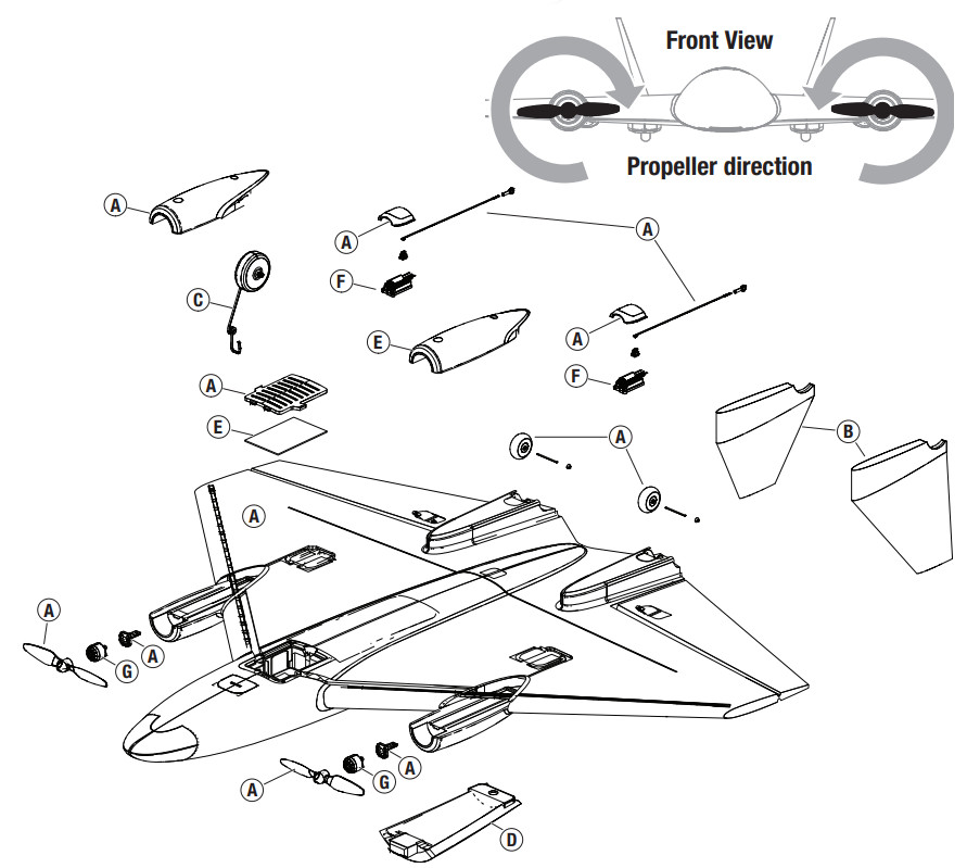
Replacement Parts List
| Part # | Description | |
| A | EFLO2201 | Replacement Airframe: Ultrix 600mm |
| B | EFL02202 | Vertical Fin Set: Ultrix 600mm |
| C | EFL02203 | Pushrod/Nosewheel: Ultrix 600mm |
| D | EFL02204 | Battery Hatch: Ultrix 600mm |
| E | SPMA3255 | RX/ESC Unit: Ultrix 600mm |
| F | SPMSH2040LW | 2.9g Linear Long Throw Servo |
| G | SPMXAM2000 | 1206-3900Kv Motor: Ultrix 600mm |
| H | EFLP9448 | Prop Set (4): Ultrix 600mm |
Recommended Parts List
| Part # | Description |
| SPMX8503S30 | 850mAh 3S Smart G2 30C; IC2 |
| SPMXC1080 | Smart S1100 AC Charger, 1x100W |
| SPMXCA320 | Adapter: IC3 Batt / IC2 Dev 6 |
Optional Parts
| Part # | Description |
| EFL02205 | LED Set: Ultrix 600mm |
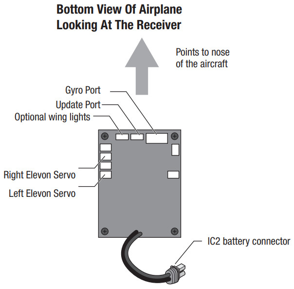
Receiver Wiring DiagramReference the following diagram for all wiring connections to the receiver.
AS3X Troubleshooting Guide
| Problem | Possible Cause | Solution |
| Control surfaces not at the neutral position when the transmitter controls are at neutral | Control surfaces not mechanically centered from factory | Center control surfaces mechanically by adjusting the U-bends on control linkages |
| The aircraft was moved after the flight battery was connected and before sensors initialized | Disconnect and reconnect the flight battery while keeping the aircraft still for 5 seconds | |
| The model flies inconsistently from flight to flight | Trims are moved too far from the neutral position | Neutralize trims and mechanically adjust linkages to center control surfaces |
| Controls oscillate in flight (model rapidly jumps or moves) | Propeller is unbalanced, causing excessive vibration | Remove propeller and motor. Check motor shaft for straightness and replace prop if damaged |
Troubleshooting Guide
| Problem | Possible Cause | Solution |
| Aircraft will not respond to throttle but responds to other controls | Throttle stick and/or throttle trim too high | Reset controls with throttle stick and throttle trim at the lowest setting |
| The throttle channel is reversed | Reverse throttle channel on the transmitter | |
| Motor disconnected from the receiver | Open fuselage and make sure motor is connected to the receiver | |
| Extra motor noise or extra vibration | Damaged propeller or motor | Replace damaged parts |
| Propeller out of balance | Balance or replace the propeller | |
| Reduced flight time oraircraft underpowered | Flight battery charge is low | Completely recharge flight battery |
| Flight battery damaged | Replace flight battery and follow flight battery instructions | |
| Flight conditions may be too cold | Make sure the battery is not cold before use | |
| Battery capacity too low for flight conditions | Replace battery or use a larger capacity battery | |
| LED on receiver flashes and aircraft will not bind to the transmitter (during binding) | Transmitter too near aircraft during the binding process | Power off the transmitter, move transmitter a larger distance from aircraft, disconnect and reconnect flight battery to aircraft and follow binding instructions |
| Bind switch or button not held long enough during the binding process | Power oft transmitter and repeat bind process. Hold transmitter bind button or switch until the receiver is bound | |
| LED on receiver flashes rapidly and aircraft will not respond to the transmitter (after binding) | Less than a 5-second wait between first powering on the transmitter and connecting flight battery to aircraft | Leaving transmitter on. disconnect and reconnect flight battery to aircraft |
| Aircraft bound to different model memory (ModelMatch ” radios only) | Select correct model memory on transmitter and disconnect and reconnect flight battery to aircraft | |
| Flight battery/transmitter battery charge is too low | Replace/recharge batteries | |
| The control surface does not move | Control surface. control horn, linkage or servo damage | Replace or repair damaged parts and adjust controls |
| Wire damaged or connections lose | Do a check of wires and connections. connect or replace as needed | |
| Flight battery charge is low | Fully recharge flight battery | |
| Control linkage does not move freely | Make sure control linkage moves freely | |
| Controls reversed | Transmitter settings reversed | Adjust controls on transmitter appropriately |
| Motor loses power | Damage to motor or power components | Do a check of motor and power components for damage (replace as needed) |
| Motor power quickly decreases and increases then the motor loses power | Battery power is down to the point of receiver/ESC Low Voltage Cutoff (LVC) | Recharge flight battery or replace the battery that is no longer performing |
| Motor/ESC is not armed after landing | Over Current Protection (0CP) stops the motor when the transmitter throttle is set high and the rotor cannot turn | Fully lower throttle and throttle trim to arm ESC |
| Servo locks or freezes at full travel | Travel adjust value is set above 100% overdriving the servo | Set Travel adjust to 100% or less and/or set sub-trims to zero and adjust linkages mechanically |
Limited Warranty
What this Warranty CoversHorizon Hobby, LLC, (Horizon) warrants to the original purchaser that the product purchased (the “Product”) will be free from defects in materials and workmanship at the date of purchase.What is Not CoveredThis warranty is not transferable and does not cover (i) cosmetic damage, (ii) damage due to acts of God, accident, misuse, abuse, negligence, commercial use, or due to improper use, installation, operation or maintenance, (iii) modification of or to any part of the Product, (iv) attempted service by anyone other than a Horizon Hobby authorized service center, (v) Product not purchased from an authorized Horizon dealer, (vi) Product not compliant with applicable technical regulations, or (vii) use that violates any applicable laws, rules, or regulations.OTHER THAN THE EXPRESS WARRANTY ABOVE, HORIZON MAKES NO OTHER WARRANTY OR REPRESENTATION, AND HEREBY DISCLAIMS ANY AND ALL IMPLIED WARRANTIES, INCLUDING, WITHOUT LIMITATION, THE IMPLIED WARRANTIES OF NON-INFRINGEMENT, MERCHANTABILITY ND FITNESS FOR A PARTICULAR PURPOSE. THE PURCHASER ACKNOWLEDGES THAT THEY ALONE HAVE DETERMINED THAT THE PRODUCT WILL SUITABLY MEET THE REQUIREMENTS OF THE PURCHASER’S INTENDED USE.Purchaser’s RemedyHorizon’s sole obligation and purchaser’s sole and exclusive remedy shall be that Horizon will, at its option, either (I) service, or (ii) replace, any Product determined by Horizon to be defective. Horizon reserves the right to inspect any and all Product(s) involved in a warranty claim. Service or replacement decisions are at the sole discretion of Horizon.Proof of purchase is required for all warranty claims.SERVICE OR REPLACEMENT AS PROVIDED UNDER THIS WARRANTY IS THE PURCHASER’S SOLE AND EXCLUSIVE REMEDY.Limitation of LiabilityHORIZON SHALL NOT BE LIABLE FOR SPECIAL, INDIRECT, INCIDENTAL, OR CONSEQUENTIAL DAMAGES, LOSS OF PROFITS OR PRODUCTION OR COMMERCIAL LOSS IN ANY WAY, REGARDLESS OF WHETHER SUCH CLAIM IS BASED IN CONTRACT, WARRANTY, TORT, NEGLIGENCE, STRICT LIABILITY OR ANY OTHER THEORY OF LIABILITY, EVEN IF HORIZON HAS BEEN ADVISED OF THE POSSIBILITY OF SUCH DAMAGES. Further, in no event, shall the liability of Horizon exceed the individual price of the Product on which liability is asserted. As Horizon has no control over use, setup, final assembly, modification or misuse, no liability shall be assumed nor accepted for any resulting damage or injury. By the act of use, setup or assembly, the user accepts all resulting liability. If you as the purchaser or user are not prepared to accept the liability associated with the use of the Product, the purchaser is advised to return the Product immediately in new and unused condition to the place of purchase.LawThese terms are governed by Illinois law (without regard to conflict of law principles). This warranty gives you specific legal rights, and you may also have other rights which vary from state to state. Horizon reserves the right to change or modify this warranty at any time without notice.WARRANTY SERVICESQuestions, Assistance, and ServicesYour local hobby store and/or place of purchase cannot provide warranty support or service. Once assembly, setup or use of the Product has been started, you must contact your local distributor or Horizon directly. This will enable Horizon to better answer your questions and service you in the event that you may need any assistance. For questions or assistance, please visit our website at www.horizonhobby.com, submit a Product Support Inquiry, or call the toll-free telephone number referenced in the Warranty and Service Contact Information section to speak with a Product Support representative.Inspection or ServicesIf this Product needs to be inspected or serviced and is compliant in the country you live and use the Product in, please use the Horizon Online Service Request submission process found on our website or call Horizon to obtain a Return Merchandise Authorization (RMA) number. Pack the Product securely using a shipping carton. Please note that original boxes may be included, but are not designed to withstand the rigors of shipping without additional protection. Ship via a carrier that provides tracking and insurance for lost or damaged parcels, as Horizon is not responsible for merchandise until it arrives and is accepted at our facility. An Online Service Request is available at http://www.horizonhobby.com/content/service-center_render-servicecenter. If you do not have internet access, please contact Horizon Product Support to obtain an RMA number along with instructions for submitting your product for service. When calling Horizon, you will be asked to provide your complete name, street address, email address, and phone number where you can be reached during business hours.When sending products into Horizon, please include your RMA number, a list of the included items, and a brief summary of the problem. A copy of your original sales receipt must be included for warranty consideration. Be sure your name, address, and RMA number are clearly written on the outside of the shipping carton.
NOTICE: Do not ship LiPo batteries to Horizon. If you have any issues with a LiPo battery, please contact the appropriate Horizon Product Support office.Warranty Requirements For Warranty consideration, you must include your original sales receipt verifying the proof-of-purchase date. Provided warranty conditions have been met, your Product will be serviced or replaced free of charge. Service or replacement decisions are at the sole discretion of Horizon.Non-Warranty ServiceShould your service not be covered by warranty, service will be completed and payment will be required without notification or estimate of the expense unless the expense exceeds 50% of the retail purchase cost. By submitting the item for service you are agreeing to payment of the service without notification. Service estimates are available upon request. You must include this request with your item submitted for service.Non-warranty service estimates will be billed a minimum of ½ hour of labor. In addition, you will be billed for return freight. Horizon accepts money orders and cashier’s checks, as well as Visa, MasterCard, American Express, and Discover cards.By submitting any item to Horizon for service, you are agreeing to Horizon’s Terms and Conditions found on our website http://www.horizonhobby.com/content/service-center_renderservice-center.ATTENTION: Horizon service is limited to Product compliant in the country of use and ownership. If received, a non-compliant Product will not be serviced.Further, the sender will be responsible for arranging return shipment of the un-serviced Product, through a carrier of the sender’s choice and at the sender’s expense. Horizon will hold non-compliant Products for a period of 60 days from notification, after which it will be discarded.
Warranty and Service Contact Information
| Country ofPurchase | Horizon Hobby | Contact Information | Address |
| United States of America | Horizon Service Center Pelts and Repair Requests) | servicecenter.horizonhobby.com/RequestForm/ | 2904 Research Rd Champaign, IL 61822 |
| Horizon Product Support (Product Technical Assistance) | [email protected] 877-504-0233 | ||
| Sales | [email protected] | ||
| 800-338-4639 | |||
| European Union | Horizon Technic her Sete | [email protected] | Hanskampring 9D 22885 BarsbiAtel, Germany |
| Sales: Horizon Hobby GmbH | +49 (0) 4121 2655 100 |
FCC Information
Contains FCC ID: BRWWACO1TThis equipment complies with FCC and IC radiation exposure limits set forth for an uncontrolled environment. This equipment should be installed and operated with a minimum distance of 20cm between the radiator and/or antenna and your body (excluding fingers, hands, wrists, ankles, and feet). This transmitter must not be co-located or operating in conjunction with any other antenna or transmitter.Supplier’s Declaration of ConformityEFL Ultrix 600mm BNF Basic (EFL02250) This device complies with part 15 of the FCC Rules. Operation is subject to the following two conditions: (1) This device may not cause harmful interference, and (2) this device must accept any interference received, including interference that may cause undesired operation.
![]() CAUTION: Changes or modifications not expressly approved by the party responsible for compliance could void the user’s authority to operate the equipment.NOTE: This equipment has been tested and found to comply with the limits for a Class B digital device, pursuant to part 15 of the FCC Rules. These limits are designed to provide reasonable protection against harmful interference in a residential installation. This equipment generates, uses, and can radiate radio frequency energy and, if not installed and used in accordance with the instructions, may cause harmful interference to radio communications. However, there is no guarantee that interference will not occur in a particular installation. If this equipment does cause harmful interference to radio or television reception, which can be determined by turning the equipment off and on, the user is encouraged to try to correct the interference by one or more of the following measures:
CAUTION: Changes or modifications not expressly approved by the party responsible for compliance could void the user’s authority to operate the equipment.NOTE: This equipment has been tested and found to comply with the limits for a Class B digital device, pursuant to part 15 of the FCC Rules. These limits are designed to provide reasonable protection against harmful interference in a residential installation. This equipment generates, uses, and can radiate radio frequency energy and, if not installed and used in accordance with the instructions, may cause harmful interference to radio communications. However, there is no guarantee that interference will not occur in a particular installation. If this equipment does cause harmful interference to radio or television reception, which can be determined by turning the equipment off and on, the user is encouraged to try to correct the interference by one or more of the following measures:
- Reorient or relocate the receiving antenna.
- Increase the separation between the equipment and receiver.
- Connect the equipment into an outlet on a circuit different from that to which the receiver is connected.
- Consult the dealer or an experienced radio/TV technician for help.
Horizon Hobby, LLC2904 Research RdChampaign, IL 61822Email: [email protected]Web: HorizonHobby.com
IC Information
Contains IC: 6157A-WACO1TCAN ICES-3 (B)/NMB-3(B)This device contains license-exempt transmitter(s)/ receivers(s) that comply with Innovation, Science, and Economic Development Canada’s license-exempt RSS(s).Operation is subject to the following 2 conditions:
- This device may not cause interference.
- This device must accept any interference, including interference that may cause undesired operation of the device.
Compliance Information for the European Union
 EU Compliance Statement:EFL Ultrix 600mm BNF Basic (EFL02250)Hereby, Horizon Hobby, LLC declares that the device is in compliance with the following: EU Radio Equipment Directive 2014/53/EU, RoHS 2 Directive 2011/65/EU, RoHS 3 Directive – Amending 2011/65/EU Annex II 2015/863The full text of the EU declaration of conformity is available at the following internet address: https://www.horizonhobby.com/content/support-render-compliance.Wireless Frequency Range and Wireless Output Power: 2404–2476MHz1.43dBm
 WEEE NOTICE:This appliance is labeled in accordance with European Directive 2012/19/EU concerning waste of electrical and electronic equipment (WEEE). This label indicates that this product should not be disposed of with household waste. It should be deposited at an appropriate facility to enable recovery and recycling.
EU Manufacturer of Record:Horizon Hobby, LLC2904 Research RoadChampaign, IL 61822 USAEU Importer of Record:Horizon Hobby, GmbHHanskampring 922885 Barsbüttel GermanyAustralia/New Zealand:

![]()
© 2021 Horizon Hobby, LLC.E-flite, Ultrix, AS3X, DSM, DSM2, DSMX, Spektrum Airware, Bind-N-Fly, BNF, the Bind-N-Fly logo, SAFE, the SAFE logo, ModelMatch, IC2, and the Horizon Hobby logo are trademarks or registered trademarks of Horizon Hobby, LLC. The Spektrum trademark is used with permission of Bachmann Industries, Inc. All other trademarks, service marks and logos are property of their respective owners.US 9,056,667. US 8,672,726. US 9,753,457. US 10,078,329. US 9,930,567. US 10,419,970. US 10,849,013.https://www.horizonhobby.comEFL02250
References
RC Airplanes and Helicopters, RC Cars and Trucks, RC Boats, RC Radios | Horizon Hobby
RC Airplanes and Helicopters, RC Cars and Trucks, RC Boats, RC Radios | Horizon Hobby
Spektrum RC Transmitters and RC Electronics | Spektrum
RC Airplanes and Helicopters, RC Cars and Trucks, RC Boats, RC Radios | Horizon Hobby
RC Airplanes and Helicopters, RC Cars and Trucks, RC Boats, RC Radios | Horizon Hobby
RC Cars, RC Trucks, RC Airplanes, Model Trains, and Slot Cars at Tower Hobbies
RC Airplanes & Helicopters, RC Cars & Trucks, RC Boats, RC Radios | Horizon Hobby
Product Serivce Center
RC Airplanes & Helicopters, RC Cars & Trucks, RC Boats, RC Radios | Horizon Hobby
[xyz-ips snippet=”download-snippet”]