![]()
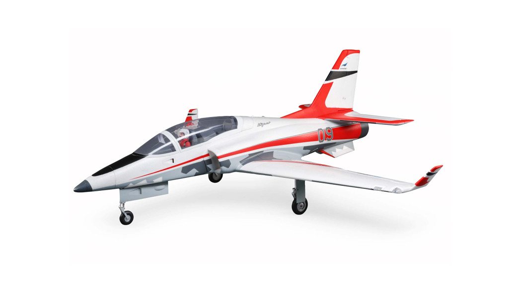
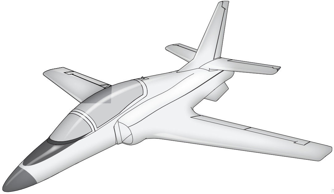
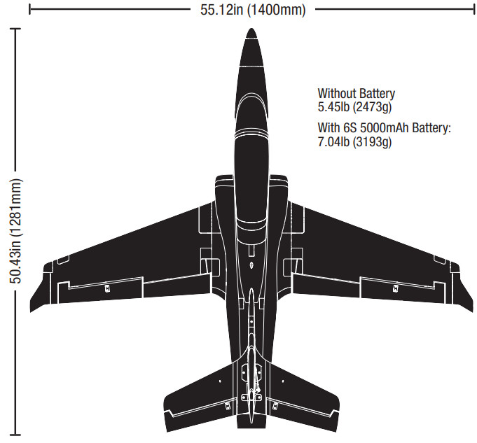
 Instruction ManualViper 90mm EDF
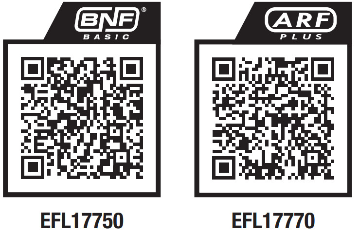
Scan the QR code and select the Manuals and Support quick links from the product page for the most up-to-date manual information.
NOTICE
All instructions, warranties, and other collateral documents are subject to change at the sole discretion of Horizon Hobby, LLC. For up-to-date product literature, visit horizonhobby.com or towerhobbies.com and click on the support or resources tab for this product.
MEANING OF SPECIAL LANGUAGEThe following terms are used throughout the product literature to indicate various levels of potential harm when operating this product:WARNING: Procedures, which if not properly followed, create the probability of property damage, collateral damage, and serious injury OR create a high probability of superficial injury.CAUTION: Procedures, which if not properly followed, create the probability of physical property damage AND a possibility of serious injury.NOTICE: Procedures, which if not properly followed, create a possibility of physical property damage AND little or no possibility of injury.![]() WARNING: Read the ENTIRE instruction manual to become familiar with the features of the product before operating. Failure to operate the product correctly can result in damage to the product, personal property and cause serious injury.This is a sophisticated hobby product. It must be operated with caution and common sense and requires some basic mechanical ability. Failure to operate this Product in a safe and responsible manner could result in injury or damage to the product or other property. This product is not intended for use by children without direct adult supervision. Do not use incompatible components or alter this product in any way outside of the instructions provided by Horizon Hobby, LLC. This manual contains instructions for safety, operation, and maintenance. It is essential to read and follow all the instructions and warnings in the manual, prior to assembly, setup or use, in order to operate correctly and avoid damage or serious injury.
WARNING: Read the ENTIRE instruction manual to become familiar with the features of the product before operating. Failure to operate the product correctly can result in damage to the product, personal property and cause serious injury.This is a sophisticated hobby product. It must be operated with caution and common sense and requires some basic mechanical ability. Failure to operate this Product in a safe and responsible manner could result in injury or damage to the product or other property. This product is not intended for use by children without direct adult supervision. Do not use incompatible components or alter this product in any way outside of the instructions provided by Horizon Hobby, LLC. This manual contains instructions for safety, operation, and maintenance. It is essential to read and follow all the instructions and warnings in the manual, prior to assembly, setup or use, in order to operate correctly and avoid damage or serious injury.
AGE RECOMMENDATION: Not for children under 14 years. This is not a toy.
Safety Precautions and Warnings
As the user of this product, you are solely responsible for operating in a manner that does not endanger yourself and others or result in damage to the product or the property of others.
- Always keep a safe distance in all directions around your model to avoid collisions or injury. This model is controlled by a radio signal subject to interference from many sources outside your control. Interference can cause momentary loss of control.
- Always operate your model in open spaces away from full-size vehicles, traffic, and people.
- Always carefully follow the directions and warnings for this and any optional support equipment (chargers, rechargeable battery packs, etc.).
- Always keep all chemicals, small parts, and anything electrical out of the reach of children.
- Always avoid water exposure to all equipment not specifically designed and protected for this purpose. Moisture causes damage to electronics.
- Never place any portion of the model in your mouth as it could cause serious injury or even death.
- Never operate your model with low transmitter batteries.
- Always keep aircraft in sight and under control.
- Always use fully charged batteries.
- Always keep the transmitter powered on while the aircraft is powered.
- Always remove batteries before disassembly.
- Always keep moving parts clean.
- Always keep parts dry.
- Always let parts cool after use before touching.
- Always remove batteries after use.
- Always ensure the failsafe is properly set before flying.
- Never operate aircraft with damaged wiring.
- Never touch moving parts.
![]() WARNING AGAINST COUNTERFEIT PRODUCTS: If you ever need to replace your Spektrum receiver found in a Horizon Hobby product, always purchase from Horizon Hobby, LLC or a Horizon Hobby authorized dealer to ensure authentic high-quality Spektrum product. Horizon Hobby, LLC disclaims all support and warranty with regards to, but not limited to, compatibility and performance of counterfeit products or products claiming compatibility with DSM or Spektrum technology.
WARNING AGAINST COUNTERFEIT PRODUCTS: If you ever need to replace your Spektrum receiver found in a Horizon Hobby product, always purchase from Horizon Hobby, LLC or a Horizon Hobby authorized dealer to ensure authentic high-quality Spektrum product. Horizon Hobby, LLC disclaims all support and warranty with regards to, but not limited to, compatibility and performance of counterfeit products or products claiming compatibility with DSM or Spektrum technology.
Quick Start Information
Specifications
 |
ARF Plus | |
| Motor: 3670-1950 Kv 4-poliger biirstenloser In- Runner (SPMXAM1400) | Installed | Required |
| Geschwindigkeitsregler: Avian Burstenloser 130-ASmart-Geschwindigkeitsregler (SPMXAE1130A) | Installed | Required |
| Servos: Querruder: (2) Spektrum SPMSA450;Linker Hohenruder: (1) Spektrum SPMSA450;Rechter Hohenruder: (1) Spektrum SPMSA450R;Ruder: (1) Spektrum SPMSA450R;Lenkung des Bugrades: (1) Spektrum SPMSA450 | Installed | Installed |
| Receive: Spektrum AR637TA AS3X/SAFETelemetrieempfanger mit 6 Kanalen (SPMAR637T) | Installed | Required |
| Recommended Battery: , 6S 22.2V 5000mAh 30C | Required | Required |
| Recommended Battery Charger: 6-zelliges LiPo- Akkuausgleichsladegerat | Required | Required |
| Recommended Battery Charger: Full range 6-channel 2.4GHz w/Spektrum DSM2/DSMX® technology w/ adjustable Dual Rates | Required | Required |
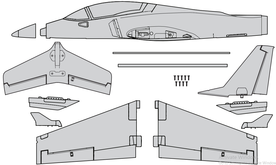
Box Contents
If you own this product, you may be required to register with the FAA.For up-to-date information on how to register with the FAA, please visit https://registermyuas.faa.gov/.For additional assistance on regulations and guidance on UAS usage, visit knowbeforeyoufly.org/
SAFE® Select Technology (BNF Basic)
The BNF Basic version of this airplane includes SAFE Select technology which can offer an extra level of protection in flight. Use the following instructions to make the SAFE Select system active and assign it to a switch. When enabled, SAFE Select prevents the airplane from banking or pitching past predetermined limits, and automatic self-leveling keeps the airplane flying in a straight and level attitude when the aileron, elevator, and rudder sticks are at neutral.SAFE Select is enabled or disabled during the binding process, or it can be enabled via forwarding Programming. When the airplane is bound with SAFE Select enabled, a switch can be assigned to toggle SAFE Select ON or OFF. AS3X® technology remains active at all times.SAFE Select can be configured three ways:
- SAFE Select Off: Always in AS3X mode
- SAFE Select On with no switch assigned: Always in SAFE Select mode
- SAFE Select On with a switch assigned
Preflight
| 1.Inhalt enffernen and iiberprOfen. |
| 2.Diese Anleitung sorgfaltig durchlesen. |
| 3.Den Flug-Akku aufladen. |
| 4.Sender laut der Sender-Einrichtungstabelle einrichten. |
| 5.Das Flugzeug komptett zusammenbauen. |
| 6.Den Flug-Akku (nach dem vollstandigen Laden) im Flugzeug montieren. |
| 7.Den Schwerpunkt (CG) iiberpriffen. |
| 8.Flugzeug mit dem Sender binden. |
| 9.OberprOfen, ob sich die Gestange unbehindert bewegen lassen. |
| 10.Testen Sie die Klappenbedienung. |
| 11.Steuerrichtungstest mit dem Sender durchffihren. |
| 12.AS3X-Steuerrichtungstest mit dem Flugzeug durchffihren. |
| 13.Fiugsteuerungen and Sender anpassen. |
| 14.Reichweitentest des Funksystems durchfuhren. |
| 15.Einen sicheren offenen Bereich zum Fliegen finden. |
| 16.Flug gernaff Bedingungen des Flugfeldes planen. |
Model Assembly
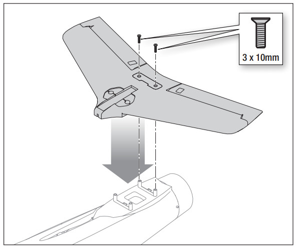
Horizontal Stabilizer Installation
- Connect both elevator servo connectors to the extensions in the fuselage labeled ELEV. Feed the excess servo wire into the fuselage.
- Press the horizontal stabilizer onto the four stabilizer posts on the fuselage, ensuring no servo wires are pinched.
- Insert two 3 x 10 mm screws through the horizontal stabilizer and into the rear holes in the fuselage.TIP: A 2.0mm hex wrench is required. Do not over-tighten the screws.

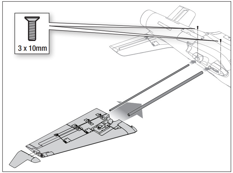
Wing Installation
- Turn the fuselage over.
- Insert the shorter wing tube (530 mm x 12.6 mm) in the forward hole of the fuselage.
- Insert the longer wing tube (580 mm x 7.8 mm) in the rear hole of the fuselage.
- Slide the left-wing panel into place on the wing tubes, ensuring the hands-free connectors align and fully seat with one another.
- Secure the wing to the fuselage with two 3 x 10 mm screws.TIP: A 2.0mm hex wrench is required. Do not over-tighten the screws. Repeat this process for the right-wing panel.
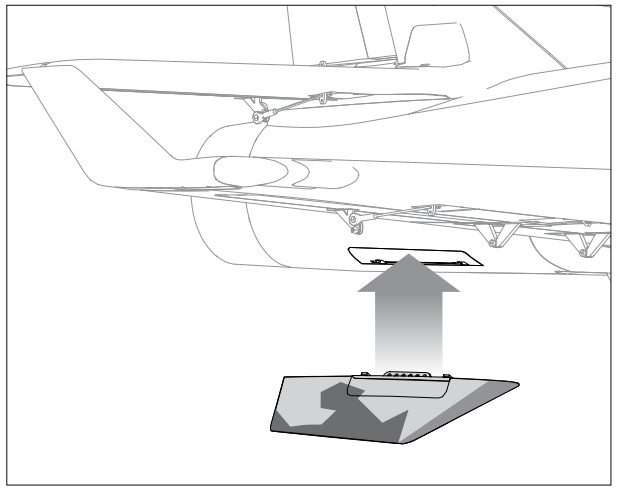
Ventral Fin Installation
- Fit the left ventral fin into the fuselage and slide aft to secure.TIP: The gray side should face in, and the detailed side should face out.
- Fit the right ventral fin into the fuselage and slide aft to secure.
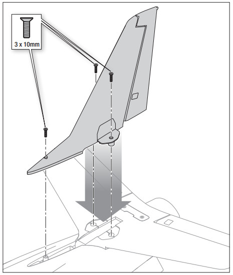
Vertical Stabilizer Installation
- Connect the rudder servo connector to the extension in the fuselage labeled RUDD. Feed the excess servo wire into the fuselage.
- Press the vertical stabilizer into the slot in the horizontal stabilizer and the fuselage, ensuring no servo wires are pinched.
- Insert three 3 x 10 mm screws through the vertical stabilizer and into the fuselage.TIP: A 2.0mm hex wrench is required. Do not overtighten the score
Nose Cone Installation
Align and attach the nose cone to the fuselage. Magnets will secure the nose cone in place.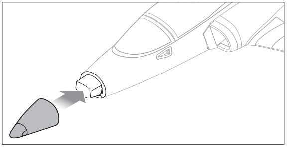
Receiver Installation (ARF Plus)
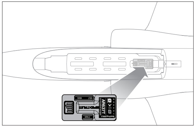
The Spektrum AR637T receiver is recommended for ths airplane. If you choose to install another receiver, ensure that it is at least a 6-channel full range (sport) receiver. Refer to your receiver manual for correct installation and operation instructions.Installation (AR637T shown)
- Mount the receiver parallel to the length of the fuselage as shown. Use heavy-duty double-sided servo tape.NOTICE: Incorrect installation of the receiver could cause a crash.
- Attach the appropriate control surfaces to their respective ports on the receiver using the chart in the illustration.
AR637 Port AssignmentsBND/PRG = BIND1 = Throttle2 = Ailerons3 = Elevator4 = Rudder5 = Retracts6 = Flap
Transmitter Setup (BNF Basic)
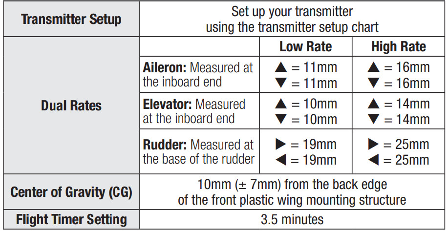
IMPORTANT: After you set up your model, always rebind the transmitter and receiver to set the desired failsafe positions.The GEAR Channel (CH 5) controls the retractable landing gear. If you are using a 6 channel transmitter, The FLAP Channel (CH 6) can be used to toggle SAFE Select. With the values listed below, it will turn SAFE on for half and full flap positions and AS3X will be on for no flaps position.To use the flap channel for the SAFE Select switch the values must be set to +100 and -100 and the speed set to 0 temporarily to assign the safety switch in the flap system menu. Then change the flap systems values back to the listing in the TX setup. See the SAFE Select Switch Designation section of this manual to assign the switch for SAFE Select.Dual RatesAttempt your first flights at a low rate. For landings, use a high rate elevator.NOTICE: To ensure AS3X technology functions properly do not lower rate valuesbelow 50%. If less control deflection is desired, manually adjust the position ofthe pushrods on the servo armNOTICE: If oscillation occurs at high speed, refer to the Troubleshooting Guide for more information.ExponentialAfter the first flights, you may adjust the expo in your transmitter.
tSome of the terminology and function locations used in the iX12 and iX20 programming may be slightly different than other Spektrum AirWare™ radios.The names given in parentheses correspond to the iX12 and iX20 programming terminology. Consult your transmitter manual for specific information about programming your transmitter.* Flap programming values may vary slightly. For your initial flights use the recommended flap travel settings and adjust the flap travel to your preference on subsequent flights.
Computerized Transmitter Setup
| Computerized Transmitter Setup | ||
| Start all transmitter programming with a blank ACRO model (perform a model reset), then name the model. | ||
| Set Dual Rates to | HIGH 100% | LOW 70% |
| Set Servo Travel to | 100% | |
| Set Throttle Cut to | -100% | |
| Set Retract Channel to | Reverse | |
| Set Aileron Expo to | High Rate 10% | Low Rate 5% |
| Set Elevator Expo to | High Rate 10% | Low Rate 5% |
| Set Rudder Expo to | High Rate 10% | Low Rate 5% |
| DXS | Refer to spektrumrc.com for the approx late download setup. | |
| DX7S DX8 | 1. Go to the SYSTEM SETUP | |
| 2. Set MODEL TYPE: AIRPLANE | ||
| 3. Set WING TYPE: 1 AIL; 1 FLP | ||
| 4. Set FLAP SYSTEM: Choose RapPOS 0: 100% FLAP`POS 1: 0% FLAP*POS 2: -100% FLAP*Switch: SWITCH DSpeed: 2.0S 1 | 0% ELEVATOR -3% ELEVATOR -5% ELEVATOR | |
| DX6eDX6 (Gen2)DX7 (Gen2) DX8eDX8 (Gen2)DX9DX10t DX18 DX20 iX12iX20NX6NX8NX10 | 1. Go to the SYSTEM SETUP (Model Utility es)r | |
| 2. Set MODEL TYPE: AIRPLANE | ||
| 3. Set AIRCRAFT TYPE (Model Setup, Aircraft Type)+: WING: 1 AIL; 1 FLP | ||
| 4. Set CHANNEL ASSIGN (Model Setup, Channel Assign)r: (Default switch assignments with a new model setup) Gear (CH5): SWITCH A | ||
| 5. Set FLAP SYSTEM:Switch: SWITCH DPOS 0: 100% FLAP*POS 1: 0% FLAP*POS 2: -100% FLAP*Speed: 2.0S | 0% ELEVATOR-3% ELEVATOR-5% ELEVATOR |
Battery Installation and ESC Arming
Battery Selection
A 6S 4000–7000mAh LiPo battery is required. The Spektrum 5000mAh 22.2V 6S 30C LiPo battery (SPMX50006S30) is recommended. Refer to the Optional Parts List for other recommended batteries. If using a battery other than those listed, the battery should be within the range of capacity, dimensions and weight of the Spektrum Li-Po battery packs to fit in the fuselage. Be sure the model balanceswithin the recommended CG range before flying.
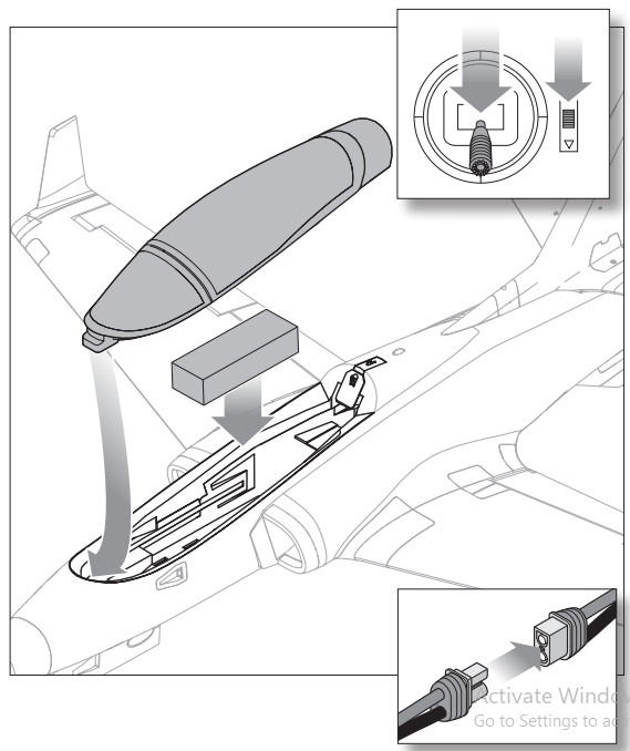
- Lower the throttle and throttle trim to the lowest settings. Power on the transmitter then waits 5 seconds.
- Remove the battery hatch.
- For added security, apply the loop side (soft side) of the optional hook and loop tape to the bottom of your battery, and the hook side to the battery tray.
- Install the fully charged battery in the center of the battery compartment as shown. Secure using the hook and loop straps.
- Connect the battery to the ESC. If you have not completed the bind sequence, do so at this time as outlined in this manual.
CAUTION: Always keep hands and loose items away from the fan intake. When armed, the motor will turn the rotor in response to any throttle movement.
- Keep the aircraft immobile and away from wind or the system will not initialize.• The motor will emit a series of rising tones when the battery is connected, and then 6 even tones indicating the number of cells connected.• An LED will light on the receiver when it is initialized
- Reinstall the battery hatch.
ESC Tones
If the ESC sounds like a continuous double beep after the flight battery is connected, recharge or replaces the battery.
| ESC Error Tones | Tone Meaning | Possible problem |
| Continuous slow single tones | Abnormal throttle signal | Transmitter and receiver not bound |
| Throttle lead damaged or not plugged into the receiver | ||
| Throttle lead plugged into receiver backward | ||
| Continuous rapid single tones | Throttle signal not at a low position | Throttle stick not at a low position |
| Throttle travel reduced below 100% | ||
| Throttle reversed | ||
| Throttle trim raised | ||
| Continuous double tones | Battery voltage is beyond the acceptable range | Verify the battery is a 22.2V 6-cell LiPo |
| Verify the battery is fully charged |
Center of Gravity
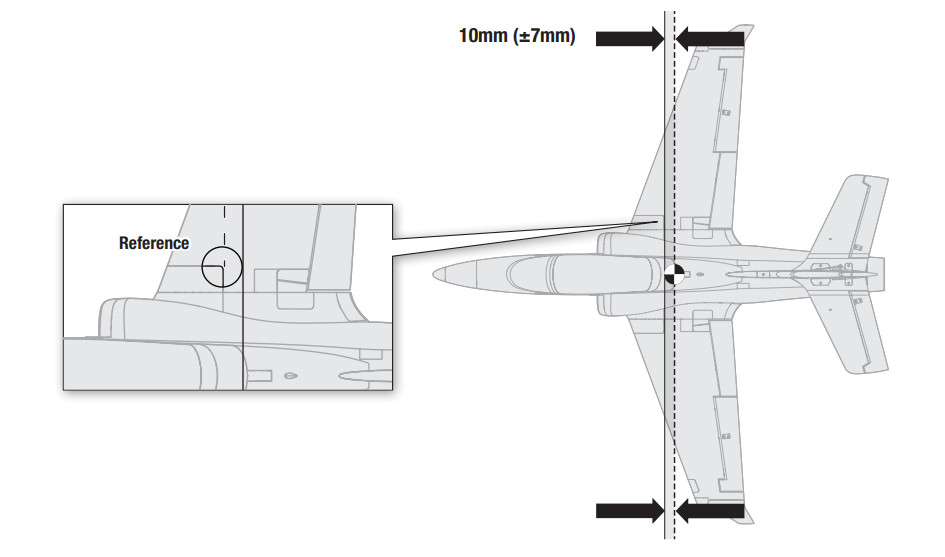
WARNING: Install the battery but do not connect it to the ESC while checking the CG. Personal injury may result.The CG location is 10mm (±7mm) from the back edge of the front plastic wing mounting structure. Always check the CG location with the model inverted, and the landing gear down.The CG location is adjusted by moving the battery pack forward or backward in the battery compartment.
General Binding Tips and Failsafe
- The included receiver has been specifically programmed for the operation of this aircraft. Refer to the receiver manual for correct setup if the receiver is replaced.
- Keep away from large metal objects while binding.
- Do not point the transmitter’s antenna directly at the receiver while binding.
- The orange LED on the receiver will flash rapidly when the receiver enters bind mode.
- Once bound, the receiver will retain its bind settings for that transmitter until you re-bind.
- If the receiver loses transmitter communication, the failsafe will activate. Failsafe moves the throttle channel to low throttle. Pitch and roll channels move to actively stabilize the aircraft in a descending turn.
- If problems occur, refer to the troubleshooting guide or if needed, contact the appropriate Horizon Product Support office.
Transmitter and Receiver Binding / Enable or Disable SAFE Select (BNF Basic)
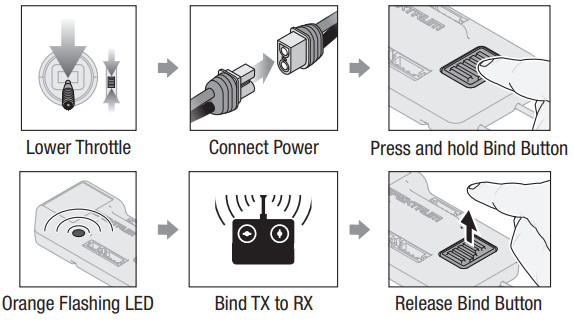
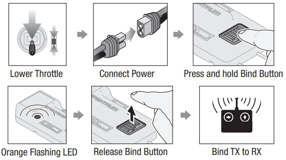
The BNF Basic version of this airplane includes SAFE Select technology, enabling you to choose the level of flight protection. The SAFE model includes angle limits and automatic self-leveling. AS3X mode provides the pilot with a direct response to the control sticks. SAFE Select is enabled or disabled during the binding process. With SAFE Select disabled the aircraft is always in AS3X mode. With SAFE Select enabled the aircraft will be in SAFE Select mode all the time, or you can assign a switch to toggle between SAFE Select and AS3X modes.Thanks to SAFE Select technology, this aircraft can be configured for full-time SAFE mode, full-time AS3X mode, or mode selection can be assigned to a switch.IMPORTANT: Before binding, read the transmitter setup section in this manual and complete the transmitter setup table to ensure your transmitter is properly programmed for this aircraft.IMPORTANT: Move the transmitter flight controls (rudder, elevators, and ailerons) and the throttle trim to neutral. Move the throttle to low before and during binding. This process defines the failsafe settings.You can use either the bind button on the receiver case OR a conventional bind plug to complete the binding and SAFE Select process.SAFE can also be enabled via forwarding Programming.
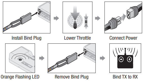
To Enable SAFE Select
SAFE SELECT ENABLED: The control surfaces cycle back and forth twice with a slight pause at a neutral position every time the receiver is powered on.
To Enable SAFE Select
SAFE SELECT DISABLED: The control surfaces cycle back and forth once every time the receiver is powered on.
Using The Bind Plug…
To Enable SAFE Select
SAFE SELECT ENABLED: The control surfaces cycle back and forth twice with a slight pause at a neutral position every time the receiver is powered on.
To Disable SAFE Select
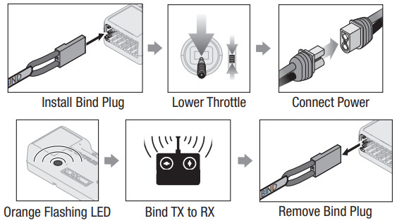
SAFE SELECT DISABLED: The control surfaces cycle back and forth once every time the receiver is powered on.
SAFE® Select Switch Designation
SAFE® Select technology can be assigned to any open switch (2 or 3 positions) controlling a channel (5–9) on your transmitter. Once assigned to a switch, SAFE select ON gives you the flexibility to choose SAFE technology or AS3X mode while in flight. If the aircraft is bound with SAFE select OFF, the aircraft will be in AS3X mode exclusively.IMPORTANT: Before assigning your desired switch, ensure that the travel for that channel is set at 100% in both directions and the aileron, elevator, rudder, and throttle are all at a high rate with the travel at 100%.CAUTION: Keep all body parts well clear of the rotor and keep the aircraft securely restrained in case of accidental throttle activation.TIP: SAFE Select is assignable on any unused channels 5–9. See your transmitter manual for more information about assigning a switch to a channel.TIP: Use your radio channel monitor to confirm that the four primary channels are showing 100% travel while assigning the switch.TIP: Use the channel monitor to make sure the switch you are assigning for SAFE Select is active and driving a channel between 5-9 and that it is traveling 100% in each direction.TIP: Make sure your four primary channels are not reversed if you are having trouble assigning a SAFE Select switch.
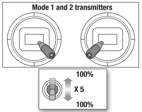
Assigning a switch
- Bind the aircraft to choose SAFE Select ON. This will allow the system to be assigned to a switch.
- Hold both transmitters sticks to the inside bottom corners and toggle the desired switch 5 times (1 toggle = full up and down) to assign that switch. The control surfaces of the aircraft will move, indicating the switch has been selected.
Repeat the process to assign a different switch or to deactivate the current switch if desired.
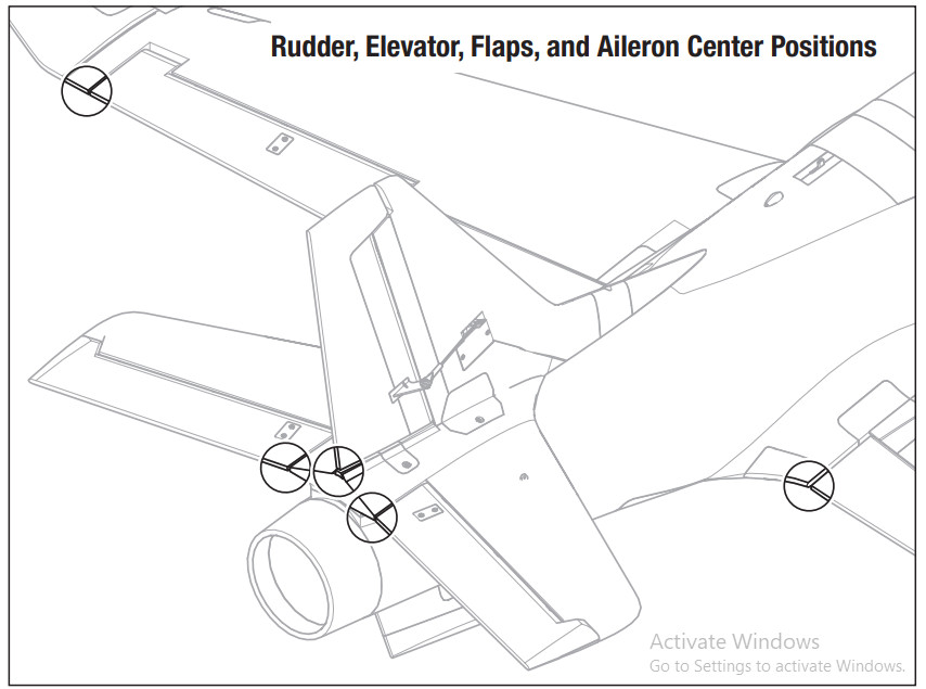
Control Surface Centering
After assembly and transmitter setup, confirm that the control surfaces are centered. The model must be powered up and bound to the transmitter in AS3X mode, with the throttle left at zero. When enabled, SAFE mode is active at power-up. AS3X mode is activated when the throttle is raised above 25% for the first time after being powered on. It is normal for the control surfaces to respond to aircraftmovement if the aircraft is in AS3X or SAFE modes.
- Verify the trims and sub trims on your transmitter are zero
- Power up the model in AS3X mode and leave the throttle at zeroNOTICE: Be aware of the pushrod bottoming out in the ball linkage. Do not thread the pushrod too far into the ball link or the pushrod will damage the ball link and protrude into the area needed for the control ball.
- Center the rudder with the bottom of the vertical stabilizer. If adjustment is required, turn the ball link on the linkage to change the length between the servo arm and the control horn until the rudder is straight.
- Center the ailerons by aligning the outboard end of the aileron with the trailing edge of the wing. Adjust the linkage length as in step 3 as necessary.
- Center the elevators with the inside portion of the horizontal stabilizer trailing edge. Adjust the linkage length as in step 3 as necessary.
- Center the flaps by aligning the inboard end of the flaps with the wing fillet of the fuselage. Adjust the linkage length as in step 3 as necessary.
Control Surface Direction
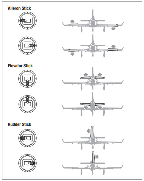
Switch on the transmitter and connect the battery. Use the transmitter to operate the aileron, elevator, and rudder controls. View the aircraft from the rear when checking the control directions.Ailerons
- Move the aileron stick to the left. The right aileron should move down and the left aileron up, which will cause the aircraft to bank left.
- Move the aileron stick to the right. The right aileron should move up and the left aileron down, which will cause the aircraft to bank right.Elevators
- Pull the elevator stick back. The elevators should move up, which will cause the aircraft to pitch up.
- Push the elevator stick forward. The elevators should move down, which will cause the aircraft to pitch down.Rudder
- Move the rudder stick to the left. The rudder and the nose wheel should move to the left, which will cause the aircraft to yaw left.
- Move the rudder stick to the right. The rudder and the nose wheel should move to the right, which will cause the aircraft to yaw right.
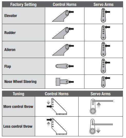
Control Horn and Servo Arm Settings
The table to the right shows the factory settings for the control horns and servo arms. Fly the aircraft at factory settings before making changes.NOTICE: If control throws are changed from the factory settings, the AR637TA gain values may need to be adjusted. Refer to the Spektrum AR637TA manual for adjustment of gain values.After flying, you may choose to adjust the linkage positions for the desired control response. See the table to the right.
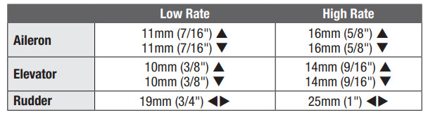
Dual Rates and Control Throws
Program your transmitter to set the rates and control throws based on your experience level. These values have been tested and are a good starting point to achieve a successful first flight.After flying, you may choose to adjust the values for the desired control response.
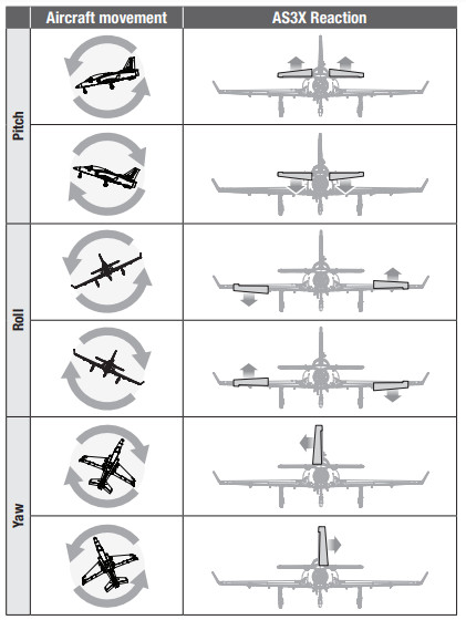
AS3X Control Response Test (BNF Basic
This test ensures that the AS3X control system is functioning properly. Assemble the aircraft and bind your transmitter to the receiver before performing this test.
- Raise the throttle to any setting above 25%, then lower the throttle to activate AS3X technology.
CAUTION: Keep all body parts, hair, and loose clothing away from the fan intake, as these items could become entangled.
- Move the entire aircraft as shown and ensure the control surfaces move in the direction indicated in the graphic. If the control surfaces do not respond as shown, do not fly the aircraft. Refer to the receiver manual for more information.Once the AS3X system is active, control surfaces may move rapidly. This is normal.AS3X remains active until the battery is disconnected.
In-Flight Trimming (BNF Basic)
During your first flight, trim the aircraft for level flight. Make small trim adjustments with your transmitter’s trim switches to straighten the aircraft’s flight path.After adjusting the trim, do not touch the control sticks for 3 seconds. This allows the receiver to learn the correct settings to optimize AS3X performance.Failure to do so could affect flight performance.

Flying Tips and Repairs
Consult local laws and ordinances before choosing a flying location.Getting StartedBefore you fly, range checks the radio system. Refer to your specific transmitter instruction manual for range test information. When you first connect the battery to the airplane AS3X will not be active. After advancing the throttle past 25% the first time, the AS3X system will be active and it is normal to see the control surfaces react to aircraft movement. For your first flights set your transmitter timer or a stopwatch to 3.5 minutes. Adjust your timer for longer or shorter flights once you have flown the model.TakeoffFace the aircraft into the wind for takeoff. Set your transmitter to low rates, set the flaps to the take-off position, and gradually increase to full throttle. Steer on the ground with the rudder as necessary to keep the aircraft rolling straight. Be aware the nose wheel will become more sensitive as speed increases. Leave the elevator at neutral and allow the aircraft to accelerate up to speed on the ground, then pull up gently on the elevator to rotate for takeoff. When airborne, climb to a comfortable altitude, retract the landing gear, and raise the flaps to normal position.FlyingFor your first flight climb to a moderate altitude and get comfortable with the aircraft while the battery is fresh. Get a feel for the aircraft’s low-speed performance at a safe altitude (approximately 100 feet or more) before being required to make your first landing attempt. Land the aircraft when the timer expires. If at any time the motor power reduces, land the aircraft immediately to recharge the flight battery. See the Low Voltage Cutoff (LVC) section for more details on maximizing battery health and run time.LandingPlan to land the aircraft into the wind when possible. Fly downwind, set the flaps to the take-off flap position, and turn into the wind to begin the approach. Extend the landing gear, lower the throttle. During the approach and descent, keep the wings level and the aircraft pointed into the wind. The attitude (angle of the aircraft relative to the horizon) should remain consistent and slightly nose-high during thedescent. With the angle of attack maintained during the descent, the speed and descent rate is mostly controlled with small throttle changes. Once confirmed, you can make the runway set the flaps to the landing position, and stay in the throttle to maintain speed and control during descent until the aircraft is ready to flare. As the airplane descends into the ground effect, fully lower the throttle, pull the nose upmore to bleed off airspeed (flare), and the aircraft will settle on its wheels.
If landing on grass, it is best to hold full-up elevator after touchdown and when taxiing to prevent the nose from digging in. Once on the ground, avoid sharp turns until the plane has slowed enough to prevent scraping the wingtips.NOTICE: If a crash is imminent, reduce the throttle and trim fully. Failure to do so could result in extra damage to the airframe, as well as damage to the ESC and motor.NOTICE: After any impact, always ensure the receiver is secure in the fuselage. If you replace the receiver, install the new receiver in the same orientation as the original receiver or damage may result.NOTICE: Crash damage is not covered under warranty.NOTICE: When you are finished flying, never leave the aircraft in direct sunlight or in a hot, enclosed area such as a car. Doing so can damage the aircraft.Low Voltage Cutoff (LVC)When a Li-Po battery is discharged below 3V per cell, it will not hold a charge. The ESC protects the flight battery from over-discharge using Low Voltage Cutoff (LVC). Before the battery charge decreases too much, LVC removes power supplied to the motor. Power to the motor reduces, showing that some battery power is reserved for flight control and safe landing.Disconnect and remove the Li-Po battery from the aircraft after use to prevent trickle discharge. Charge your Li-Po battery to about half capacity before storage. During storage, make sure the battery charge does not fall below 3V per cell. LVC does not prevent the battery from over-discharge during storage.NOTICE: Repeated flying to LVC will damage the battery.TIP: Monitor your aircraft battery’s voltage before and after flying by using a LiPo Cell Voltage Checker (SPMXBC100, sold separately).OscillationFor most flight maneuvers the aircraft should fly smoothly and normally, but it is possible in some flight conditions you may see oscillation (the aircraft rocks back and forth on one axis). If oscillation occurs, refer to the Troubleshooting Guide for more information.RepairsThanks to the EPO foam material in this aircraft, repairs to the foam can be made using virtually any adhesive (hot glue, regular CA, epoxy, etc). When parts are not repairable, see the Replacement Parts List for ordering by item number. For a listing of all replacement and optional parts, refer to the list at the end of this manual.NOTICE: Use of CA accelerant on your aircraft can damage the paint. DO NOT handle the aircraft until the accelerant fully dries.
SAFE Select Flying Tips
When flying in SAFE Select mode the aircraft will return to level flight any time the aileron and elevator controls are at neutral. Applying aileron or elevator control will cause the airplane to the bank, climb or dive, and the amount the stick is moved will determine the attitude the airplane flies. Holding full control will push the aircraft to the pre-determined pitch and roll limits, but it will not go past those angles.When flying with SAFE Select it is normal to hold the control stick deflected with moderate aileron input when flying through a turn. To fly smoothly with SAFE Select avoid making frequent control changes and don’t attempt to correct for minor deviations. With SAFE Select, holding deliberate control inputs will command the aircraft to fly at a specific angle and the model will make all corrections to maintain that flight attitude.Return the elevator and aileron controls to neutral before switching from SAFESelect mode to AS3X mode. If you do not neutralize controls when switching intoAS3X mode, the control inputs used for SAFE Select mode will be excessive forAS3X mode and the aircraft will react immediately.
Differences between SAFE Select and AS3X modesThis section is generally accurate but does not take into account flight speed, battery charge status, and many other limiting factors.
- In SAFE Select mode the aircraft will self-level when the control stick is neutralized. In AS3X mode the aircraft will continue to flyat its present attitude when the control stick is neutralized.
- In SAFE Select mode holding a small amount of control will result in the model banking or pitching to a moderate angle and remaining at that angle as long as the control stick doesn’t move.In AS3X mode holding a small amount of control will result in the model continuing to pitch or roll at a slow rate as long as the control stick doesn’t move.
- In SAFE Select mode holding full control will result in the airplane banking or pitching to the predetermined limits and the aircraft will keep flying at that attitude as long as the control stick is fully deflected.In AS3X mode holding full control will result in the aircraft pitching or rolling at a high rate and it will continue to rapidly change attitude as long as the control stick is fully deflected.
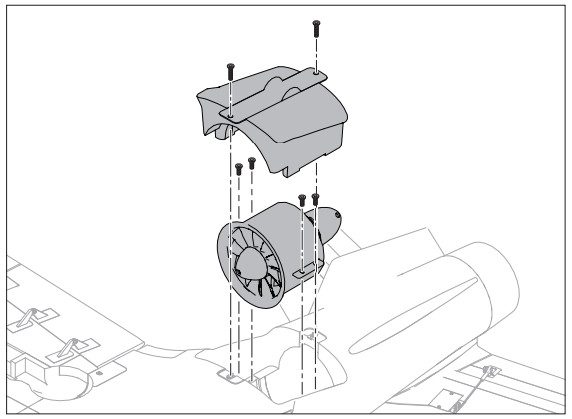
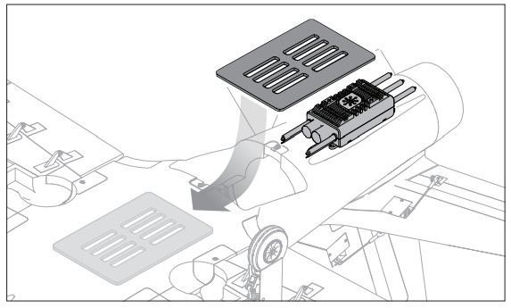
Power System Installation and Service
- Remove the two screws from the fan unit cover and pull the cover out of the fuselage.
- Feed the ESC battery and throttle leads through the small hole at the front of the ESC compartment and into the battery compartment.
- Feed the motor leads through the trough under the fan shroud location.
- Install the ESC in the fuselage.
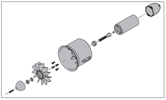
- Assemble motor to the fan housing.
- Install the rotor adapter to the motor shaft.
- Install the rotor to the rotor adapter with the rotor nut, nose cone and nose cone screw. Ensure the rotor nut is tightened securely before installing the nose cone.
- Connect the motor wires to the ESC motor leads.
- Install the fan unit into the fuselage using four screws through the fan unit tabs.
- Install the fan unit cover with the two screws removed in Step 1.
- Connect the throttle lead to the aircraft receiver.
CAUTION: Always disconnect the flight battery before performing motor service.
Disassembly
- Remove the two screws from the fan unit cover and pull the cover off the fuselage.
- Remove the four screws from the fan unit tabs.
- Pull the fan unit out of the fuselage, take note of the wiring order, and disconnect the motor leads from the ESC.
- Remove the rotor cone screw, rotor cone, rotor nut, and washer from the rotor adapter.
- Remove the rotor by pulling it off the rotor adapter.
- Remove the rotor adapter from the motor shaft.
- Remove the four 3mm hex head screws that hold the motor in the fan housing.
AssemblyAssemble in reverse order.
- Correctly align and connect the motor wire colors with the ESC wires.
- Install the rotor as shown.
- Tighten the nut on the motor adapter to secure the rotor into place.
Post Flight
| 1.Den Flug-Akku vom Geschwindigkeitsregler trennen (fEir die Sicherheit and die Lebensdauer des Akkus erforderlich). |
| 2.Sender ausschalten. |
| 3.Den Flug-Akku vom Flugzeug enffernen. |
| 4.Akku des Fluggerats auf Speicherspannung aufladen. |
| 5.Alle beschadigten Teile reparieren oder ersetzen. |
| 6.Den Flug-Akku getrennt vom Flugzeug lagem und den Akku-Ladezustand iiberwachen. |
| 7.Mit Blick auf die Planung zukiinftiger Huge, die Flugbedingungen und |
Troubleshooting Guide AS3X
| Problem | Wigliche Ursache | Losung |
| Oszillation | Beschadigter Propeller oder Spinner | Propeller oder Spinner ersetzen |
| Propeller im Ungleichgewicht | Propeller ausbalancieren | |
| Motorvibrationen | Bauteile ersetzen oder alle Bauteile korrekt ausrichten und Befestiger festziehen, je nach Bedarf | |
| Loser Empfanger | Empfanger im Rumpf ausrichten und sichern | |
| Lose Flugzeugsteuerungen | Bauteile (Servo, Arm, Gestange, Horn und Steueroberflache) festziehen oder anderweitig sichern | |
| Verschlissene Bauteile | Verschlissene Bauteile (insbesondere Propeller, Spinner oder Servo) ersetzen | |
| UngleichmaBige Servobewegungen | Servo ersetzen | |
| UngleichmaBige Flugleistung | Trimmung ist nicht auf Neutral | Wird die Trimmung fur mehr als 8 Klicks angepasst, den Gabelkopf anpassen, um Trimmung zu entfemen |
| Ersatztrimmung ist nicht auf Neutral | Keine Ersatztrimmung zugelassen. Servogestange anpassen | |
| Flugzeug wurde dem Verbinden des Akkus nicht fur 5 Sekunden still gehalten | Gashebel in niedrigster Position. Akku trennen, dann Akku wieder anschlieBen und Flugzeug fur 5 Sekunden still halten | |
| Falsche Reaktion auf den AS3X-Steuerrichtungstest | Falsche Richtungseinstellungen im Empfanger, was zu Abstijrzen fiihren kann | Das Flugzeug NICHT fliegen. Die Richtungseinstellungen korrigieren (siehe Empfanger-Handbuch), dann fliegen |
Troubleshooting Guide
| Problem | Possible Cause | Solution |
| Aircraft will not respond to throttle but responds to other controls | Throttle not at idle and/or throttle trim too high | Reset controls with throttle stick and throttle trim at the lowest setting |
| Throttle servo travel is lower than 100% | Make sure throttle servo travel is 100% or greater | |
| The throttle channel is reversed | Reverse throttle channel on the transmitter | |
| Motor disconnected from ESC | Make sure the motor is connected to the ESC | |
| Excessive fannoise or excessive vibration | Damaged fan, nose cone, collet or motor | Replace damaged parts |
| Fan is out of balance | Balance or replace fan | |
| Fan nut is too loose | Tighten the fan nut | |
| Reduced flighttime or aircraftunderpowered | Flight battery charge is low | Completely recharge flight battery |
| Flight battery damaged | Replace flight battery and follow flight battery instructions | |
| Flight conditions may be too cold | Make sure battery is not cold before use (Do not apply heat to the battery) | |
| Battery capacity too low for flight conditions | Replace battery or use a larger capacity battery | |
| Aircraft will not Bind (during binding) to the transmitter | Transmitter too near aircraft during the binding process | Move powered transmitter a few feet from aircraft, disconnect and reconnect flight battery to aircraft |
| Aircraft or transmitter is too dose to large metal object, wireless source or another transmitter | Move aircraft and transmitter to another location and attempt binding again | |
| The bind plug is not installed correctly in the bind port | Install bind plugin bind port and bind the aircraft to the transmitter | |
| Flight battery/transmitter battery charge is too low | Replace/recharge batteries | |
| Bind switch or button not held long enough during the bind process | Power off transmitter and repeat bind process. Hold transmitter bind button or switch until the receiver is bound | |
| Aircraft will not connect (after binding) to the transmitter | Transmitter too near aircraft during the connecting process | Move powered transmitter a few feet from aircraft, disconnect and reconnect flight battery to aircraft |
| Aircraft or transmitter is too dose to large metal object, wireless source or another transmitter | Move aircraft and transmitter to another location and attempt connecting again | |
| Bind plug left installed in bind port | Rebind transmitter to the aircraft and remove the bind plug before cycling power | |
| Aircraft bound to different model memory (ModelMatchTM radios only) | Select correct model memory on the transmitter | |
| Flight battery/Transmitter battery charge is too low | Replace/recharge batteries | |
| The transmitter may have been bound to a different aircraft using a different DSM protocol | Bind aircraft to the transmitter | |
| The control surface does not move | The control surface, control horn, linkage or servo damage | Replace or repair damaged parts and adjust controls |
| Wire damaged or connections lose | Do a check of wires and connections, connect or replace as needed | |
| The transmitter is not bound correctly or the incorrect airplanes was selected | Re-bind or select correct airplanes in the transmitter | |
| Flight battery charge is low | Fully recharge flight battery | |
| BEC (Battery Elimination Circuit) of the ESC is damaged | Replace ESC | |
| Controls reversed | Transmitter settings are reversed | Perform the Control Direction Test and adjust the controls on the transmitter appropriately |
| Motor power pulses then motor loses power | ESC uses default soft Low Voltage Cutoff (LVC) | Recharge flight battery or replace the battery that is no longer performing |
| Weather conditions might be too cold | Postpone flight until weather is warmer | |
| Battey,/ is old, wan out, or damaged | Replace battery | |
| Battery C rating might be too low | Use recommended battery |
Replacement Parts
| Part Number | Description |
| EFL17774 | Wing Set, Left: Viper 90mm EDF |
| EFL17776 | Wing Set, Right: Viper 90mm EDF |
| EFL17777 | Fuselage: Viper 90mm EDF |
| EFL17778 | Vertical Stabilizer: Viper 90mm EDF |
| EFL17779 | Horizontal Stabilizer: Viper 90mm EDF |
| EFL17780 | Cockpit/Hatch: Viper 90mm EDF |
| EFL17781 | Nose Cone: Viper 90mm EDF |
| EFL17782 | Winglet Set: Viper 90mm EDF |
| EFL17783 | Linkage Rod: Viper 90mm EDF |
| EFL17784 | Control Horns: Viper 90mm EDF |
| EFL17785 | Wheel Set: Viper 90mm EDF |
| EFL17786 | Screw Set: Viper 90mm EDF |
| EFL17787 | Ventral Fin Set: Viper 90mm EDF |
| EFL17788 | Decal Sheet: Viper 90mm EDF |
| EFL17789 | Gear Doors: Viper 90mm EDF |
| EFL17790 | Wing Tubes: Viper 90mm EDF |
| Part Number | Description |
| EFL17791 | Lighting Set: Viper 90mm EDF |
| EFL17792 | Pilot: Viper 90mm EDF |
| EFLA9012DF | 90mm EDF Ducted Fan Unit |
| EFLA9012H | 90mm EDF 12 Blade Rotor Hub |
| EFLA9012R | 90mm EDF 12 Blade Rotor |
| EFLG360 | Retract Unit: Nose Gear Viper 90mm EDF |
| EFLG361 | Nose Strut w/Wheel: Viper 90mm EDF |
| EFLG362 | Main Struts w/Wheel: Viper 90mm EDF |
| EFLG363 | Retract Strut Pins: Viper 90mm EDF |
| EFLG364 | Retract Unit: Main Gear 90mm EDF |
| SPMAR637T | 6CH SAFE and AS3X Telemetry Receiver |
| SPMSA450 | Servo: 13g Digital Metal Gear |
| SPMSA45OR | Servo: 13g Digital Metal Gear (Reverse) |
| SPMME1130A | Avian 130A Brushless Smart ESC 3-6S IC5 |
| SPMXAM1400 | 3670-1950Kv Brushless Inrunner Motor |
Recommended Parts
| Part Number | Description |
| DYN1405 | LiPo Charge Protection Bag, Large |
| ONXT1000 | Ultimate Air/Surface Startup Tool Set |
| SPMR8105 | DX8e 8CH Transmitter Only |
| SPMX2020 | Smart S1200 G2 AC Charger, 1x200W |
| SPMX50006S30 | 22.2V 5000mAh 6S 30C Smart LiPo, IC5 |
| SPMXBC100 | XBC100 Smart LiPo Battery Checker & Servo Driver |
Optional Parts
| Part Number | Description |
| SPM6708 | Spektrum Single Stand Up Transmitter Case |
| SPMR10100 | NX10 10CH Transmitter Only |
| SPMR8200 | NX8 8CH DSMX Transmitter Only |
| SPMX46S50 | 22.2V 4000mAh 6S 50C Smart LiPo Battery G2, IC5 |
| SPMX56S100 | 22.2V 5000mAh 6S 100C Smart LiPo Battery G2, IC5 |
| SPMX76S30 | 22.2V 7000mAh 6S 30C Smart LiPo Battery G2, IC5 |
| SPMX40006S30 | 22.2V 4000mAh 6S 30C Smart LiPo Battery, IC5 |
| SPMX40006S50 | 22.2V 4000mAh 6S 50C Smart LiPo Battery, IC5 |
| SPMX50006S100 | 22.2V 5000mAh 6S 100C Smart LiPo Battery, IC5 |
| SPMX70006S30 | 22.2V 7000mAh 6S 30C Smart LiPo Battery, IC5 |
| SPMXC1010 | Smart S2100 AC Charger, 2x100W |
| SPMXC2010 | Smart S2200 G2 AC Charger, 2x200W |
| SPMXCA200 | Avian Firma Smart ESC Programmer |
Recommended Receivers (ARF Plus)
| Part Number | Description |
| Telemetry Equipped Receivers | |
| SPMAR6610T | AR6610T 6-Channel Air Integrated Telemetry Receiver |
| SPMAR8020T | AR8020T 8-Channel Air Integrated Telemetry Receiver |
| Part Number | Description |
| AS3X and Telemetry Equipped Receivers | |
| SPMAR637T | AR637T DSMX 6-Channel AS3X Telemetry Receiver |
| SPMAR8360T | AR8360T DSMX 8-Channel AS3X & SAFE Telemetry Receiver |
AMA National Model Aircraft Safety Code
Effective January 1, 2018A model aircraft is a non-human-carrying device capable of sustained flight within the visual line of sight of the pilot or spotter(s). It may not exceed the limitations of this code and is intended exclusively for sport, recreation, education, and/or competition. All model flights must be conducted in accordance with this safety code and related AMA guidelines, any additional rules specific to the flying site, as well as all applicable laws and regulations.As an AMA member I agree:
- I will not fly a model aircraft in a careless or reckless manner.
- I will not interfere with and will yield the right of way to all human-carrying aircraft using AMA’s See and Avoid Guidance and a spotter when appropriate.
- I will not operate any model aircraft while I am under the influence of alcohol or any drug that could adversely affect my ability to safely control the model.
- I will avoid flying directly over unprotected people, moving vehicles, and occupied structures.
- I will fly Free Flight (FF) and Control Line (CL) models in compliance with AMA’s safety programming.
- I will maintain visual contact of an RC model aircraft without enhancement other than corrective lenses prescribed to me. When using an advanced flight system, such as an autopilot, or flying First-Person View (FPV), I will comply with AMA’s Advanced Flight System programming.
- I will only fly models weighing more than 55 pounds, including fuel, if certified through AMA’s Large Model Airplane Program.
- I will only fly a turbine-powered model aircraft in compliance with AMA’s Gas Turbine Program.
- I will not fly a powered model outdoors closer than 25 feet to any individual, except for myself or my helper(s) located at the flight line, unless I am taking off and landing, or as otherwise provided in AMA’s Competition Regulation.
- I will use an established safety line to separate all model aircraft operations from spectators and bystanders.
Limited Warranty
What this Warranty Covers—Horizon Hobby, LLC, (Horizon) warrants to the original purchaser that the product purchased (the “Product”) will be free from defects in materials and workmanship at the date of purchase.What is Not Covered—This warranty is not transferable and does not cover (i) cosmetic damage, (ii) damage due to acts of God, accident, misuse, abuse, negligence,commercial use, or due to improper use, installation, operation or maintenance, (iii) modification of or to any part of the Product, (iv) attempted service by anyone other than a Horizon Hobby authorized service center, (v) Product not purchased from an authorized Horizon dealer, (vi) Product not compliant with applicable technical regulations,or (vii) use that violates any applicable laws, rules, or regulations. OTHER THAN THE EXPRESS WARRANTY ABOVE, HORIZON MAKES NO OTHER WARRANTY OR REPRESENTATION, AND HEREBY DISCLAIMS ANY AND ALL IMPLIED WARRANTIES, INCLUDING, WITHOUT LIMITATION, THE IMPLIED WARRANTIES OF NON-INFRINGEMENT, MERCHANTABILITY AND FITNESS FOR A PARTICULAR PURPOSE.THE PURCHASER ACKNOWLEDGES THAT THEY ALONE HAVE DETERMINED THATTHE PRODUCT WILL SUITABLY MEET THE REQUIREMENTS OF THE PURCHASER’S INTENDED USE.Purchaser’s Remedy—Horizon’s sole obligation and purchaser’s sole and exclusive remedy shall be that Horizon will, at its option, either (i) service, or (ii) replace, any Product determined by Horizon to be defective. Horizon reserves the right to inspect any and all Product(s) involved in a warranty claim. Service or replacement decisions are at the sole discretion of Horizon. Proof of purchase is required for all warranty claims. SERVICE OR REPLACEMENT AS PROVIDED UNDER THIS WARRANTY IS THE PURCHASER’S SOLE AND EXCLUSIVE REMEDY.Limitation of Liability—HORIZON SHALL NOT BE LIABLE FOR SPECIAL, INDIRECT, INCIDENTAL OR CONSEQUENTIAL DAMAGES, LOSS OF PROFITS OR PRODUCTION OR COMMERCIAL LOSS IN ANY WAY, REGARDLESS OF WHETHER SUCH CLAIM IS BASED IN CONTRACT, WARRANTY, TORT, NEGLIGENCE, STRICT LIABILITY OR ANY OTHER THEORY OF LIABILITY, EVEN IF HORIZON HAS BEEN ADVISED OF THE POSSIBILITY OF SUCH DAMAGES.Further, in no event, shall the liability of Horizon exceed the individual price of the Product on which liability is asserted.As Horizon has no control over use, setup, final assembly, modification or misuse, no liability shall be assumed nor accepted for any resulting damage or injury. By the act of use, setup or assembly, the user accepts all resulting liability. If you as the purchaser or user are not prepared to accept the liability associated with the use of the Product, the purchaser is advised to return the Product immediately in new and unused condition to the place of purchase.Law—These terms are governed by Illinois law (without regard to conflict of law principles). This warranty gives you specific legal rights, and you may also have other rights which vary from state to state. Horizon reserves the right to change or modify this warranty at any time without notice.WARRANTY SERVICESQuestions, Assistance, and Services—Your local hobby store and/or place of purchase cannot provide warranty support or service. Once assembly, setup or use of the Product has been started, you must contact your local distributor or Horizon directly. This will enable Horizon to better answer your questions and service you in the event that you may need any assistance. For questions or assistance, please visit our website at www.horizonhobby.com, submit a Product Support Inquiry, or call the toll free telephone number referenced in the Warranty and Service Contact Information section to speak with a Product Support representative.Inspection or Services—If this Product needs to be inspected or serviced and is compliant in the country you live and use the Product in, please use the Horizon Online Service Request submission process found on our website or call Horizon to obtain a Return Merchandise Authorization (RMA) number. Pack the Product securely using a shipping carton. Please note that original boxes may be included, but are not designed to withstand the rigors of shipping without additional protection. Ship via a carrier that provides tracking and insurance for lost or damaged parcels, as Horizon is not responsible for merchandise until it arrives and is accepted at our facility.An Online Service Request is available at http://www.horizonhobby.com/content/service-center_renderservice-center. If you do not have internet access, please contact Horizon Product Support to obtain an RMA number along with instructions for submitting your product for service.When calling Horizon, you will be asked to provide your complete name, street address, email address, and phone number where you can be reached during business hours.When sending products into Horizon, please include your RMA number, a list of the included items, and a brief summary of the problem.A copy of your original sales receipt must be included for warranty consideration. Be sure your name, address, and RMA number are learly written on the outside of the shipping carton.NOTICE: Do not ship LiPo batteries to Horizon. If you have any issue with a LiPo battery, please contact the appropriate Horizon product Support office.Warranty Requirements—For Warranty consideration, you must include your original sales receipt verifying the proof-of-purchase date. Provided warranty conditions have been met, your Product will be serviced or replaced free of charge. Service or replacement decisions are at the sole discretion of Horizon.Non-Warranty Service—Should your service not be covered by warranty, service will be completed and payment will be required without notification or estimate of the expense unless the expense exceeds 50% of the retail purchase cost. By submitting the item for service you are agreeing to payment of the service without notification.Service estimates are available upon request. You must include this request with your item submitted for service. Non-warranty service estimates will be billed a minimum of ½ hour of labor. In addition, you will be billed for return freight. Horizon accepts money orders and cashier’s checks, as well as Visa, MasterCard, American Express, and Discover cards. By submitting any item to Horizon for service, you are agreeing to Horizon’s Terms and Conditions found on our website http://www.horizonhobby.com/content/service-center_render-service-center.ATTENTION: Horizon service is limited to Product compliant in the country of use and ownership. If received, a non-compliant Product will not be serviced. Further, the sender will be responsible for arranging return shipment of the un-serviced Product, through a carrier of the sender’s choice and at the sender’s expense. Horizon will hold non-compliant Products for a period of 60 days from notification, after which it will be discarded.
Contact Information
| Country of Purchase | Horizon Hobby | Contact Information | Address |
| United Statesof America | Horizon Service Center (Repairs and Repair Requests) | servicecenterhorizonhobby.com/RequestForm/ | 2904 Research RdChampaign, Illinois, 61822 USA |
| Horizon Product Support (Product Technical Assistance) | 877-504-0233 | ||
| Sales | 800-338-4639 | ||
| European Union | Horizon Technischer ServiceSales: Horizon Hobby GmbH | +49 (0) 4121 2655 100 | Hanskampring 9D 22885 BarsbEittel, Germany |
FCC Information
FCC ID: BRWTIARLGTNG1This equipment complies with FCC and IC radiation exposure limits set forth for an uncontrolled environment. This equipment should be installed and operated with a minimum distance 20cm between the radiator and/or antenna and your body (excluding fingers, hands, wrists, ankles, and feet). This transmitter must not be co-located or operating in conjunction with any other antenna or transmitter.
Supplier’s Declaration of Conformity

EFL Smart Viper ARF Plus (EFL17770)EFL Smart Viper EDF BNF-B (EFL17750)This device complies with part 15 of the FCC Rules. Operation is subject to the following two conditions: (1) This device may not cause harmful interference, and (2) this device must accept any interference received, including interference that may cause undesired operation.

CAUTION: Changes or modifications not expressly approved by the party responsible for compliance could void the user’s authority to operate the equipment.
NOTE: This equipment has been tested and found to comply with the limits for a Class B digital device, pursuant to part 15 of the FCC Rules. These limits are designed to provide reasonable protection against harmful interference in a residential installation. This equipment generates, uses and can radiate radio frequency energy and, if not installed and used in accordance with the instructions, may cause harmful interference to radio communications. However, there is no guarantee that interference will not occur in a particular installation. If this equipment does cause harmful interference to radio or television reception, which can be determined by turning the equipment off and on, the user is encouraged to try to correct the interference by one or more of the following measures:
- Reorient or relocate the receiving antenna.
- Increase the separation between the equipment and receiver.
- Connect the equipment into an outlet on a circuit different from that to which the receiver is connected.
- Consult the dealer or an experienced radio/TV technician for help.
Horizon Hobby, LLC2904 Research Rd.,Champaign, IL 61822Email: [email protected]Web: HorizonHobby.com
IC Information
CAN ICES-3 (B)/NMB-3(B)IC: 6157A-TIARLGTNG1This device contains license-exempt transmitter(s)/receivers(s) that comply with Innovation, Science, and Economic Development Canada’s license-exempt RSS(s).Operation is subject to the following 2 conditions:
- This device may not cause interference.
- This device must accept any interference, including interference that may cause undesired operation of the device.
Compliance Information for the European Union
EU Compliance Statement:EFL Smart Viper ARF Plus (EFL17770): Hereby, Horizon Hobby, LLC declares that the device is in compliance with the following: EU EMCDirective 2014/30/EU. RoHS 2 Directive 2011/65/EU, RoHS 3 Directive– Amending 2011/65/EU Annex II 2015/863.EFL Smart Viper EDF BNF-B (EFL17750): Hereby, Horizon Hobby, LLC declares that the device is in compliance with the following: EU Radio Equipment Directive 2014/53/EU, RoHS 2 Directive 2011/65/EU, RoHS 3 Directive – Amending 2011/65/EU Annex II 2015/863.The full text of the EU declaration of conformity is available at the following internet address: https://www.horizonhobby.com/content/support-render-compliance.Wireless Frequency Range and Wireless Output Power:2402 – 2478 MHz19.95dBm

EU Manufacturer of Record:Horizon Hobby, LLC2904 Research RoadChampaign, IL 61822 USAEU Importer of Record:Horizon Hobby, GmbHHanskampring 922885 Barsbüttel GermanyWE NOTICE:

This appliance is labeled in accordance with European Directive 2012/19/EU concerning waste of electrical and electronic equipment(WEEE). This label indicates that this product should not be disposed of with household waste. It should be deposited at an appropriate facility to enable recovery and recycling.
References
RC Airplanes and Helicopters, RC Cars and Trucks, RC Boats, RC Radios | Horizon Hobby
Product Service Center – Request Form
RC Cars, RC Trucks, RC Airplanes, Model Trains, and Slot Cars at Tower Hobbies
Spektrum RC Transmitters and RC Electronics | Spektrum
Home – Know Before You Fly
RC Airplanes and Helicopters, RC Cars and Trucks, RC Boats, RC Radios | Horizon Hobby
registermyuas.faa.gov/
RC Airplanes and Helicopters, RC Cars and Trucks, RC Boats, RC Radios | Horizon Hobby
RC Airplanes and Helicopters, RC Cars and Trucks, RC Boats, RC Radios | Horizon Hobby
RC Airplanes and Helicopters, RC Cars and Trucks, RC Boats, RC Radios | Horizon Hobby
RC Airplanes and Helicopters, RC Cars and Trucks, RC Boats, RC Radios | Horizon Hobby
RC Airplanes and Helicopters, RC Cars and Trucks, RC Boats, RC Radios | Horizon Hobby
RC Cars, RC Trucks, RC Airplanes, Model Trains, and Slot Cars at Tower Hobbies
Horizon Hobby Compliance Information
[xyz-ips snippet=”download-snippet”]