
![]()
VERSION 1
ASSEMBLY AND OPERATION INSTRUCTIONS MANUAL
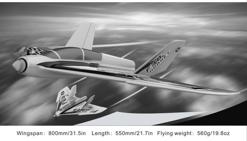
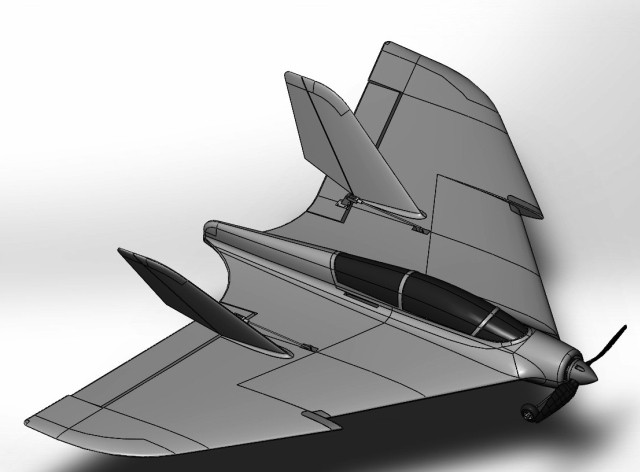
Thank you for purchasing the new F38 HORNET from Xane.Assembly for this aircraft is kept at a minimum.This plane is powered by a brushless outrunner motor paired with a factory calibrated electronic speed controller, ailerons control surfaces are controlled by servos; all of which are factory installed on the Ready-to-Fly version. If you have KIT version, this manual also will let you know how to assembly it and make the plane to Ready-to-Fly version.Please be sure to read the entire manual carefully prior to assembling/operating the F38 Hornet.
Specifications
Package Contents
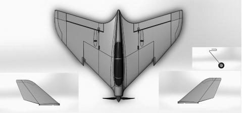
ARF(PNP) Version
- Fuselage with factory installed motor, electronic speed controller and servos
- Vertical stabilizer
- Landing gear
Before assembling the model
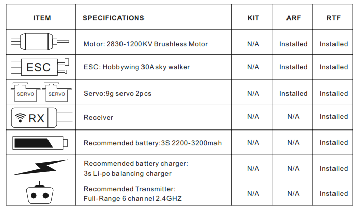
Please check the contents of your kit before you start working on it.You need :
- Servo—–2pcs
- Motor——2830-1200KV and 8×6 propellers
- ESC——–30A hobby wing
Preparation
Fig. 1 Main wing panel.
- Apply adhesive (not included) to the servo holes, and then located the servo into the hole.
- Install the control horns with screw.
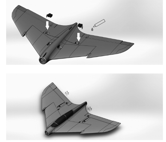
Fig. 2 Main wing panel.
- Adjusting the Clevis
- Turn the clevis (A) clockwise or counterclockwise on the linkage.
- Carefully spread the clevis and put the clevis pin (B) in a selected hole in the control horn (C).
- Connect the push rod with servo arm and control horns
- Verify the control surface tips are mechanically centered.
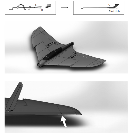
Fig. 3 Assembly the tail wing.1. Apply adhesive(not include) to the Vertical fin and then glued with fuselage.
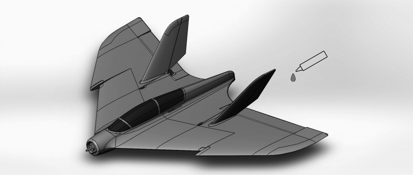
Fig. 4 Assembly the propellers.
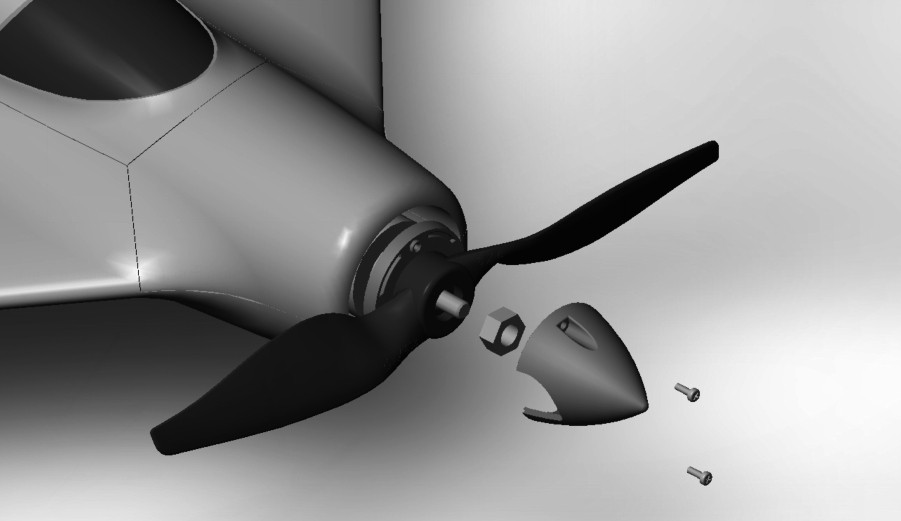
Fig. 5 Assembly the landing gear.
- Push the landing gear into the hole of the plastic set.
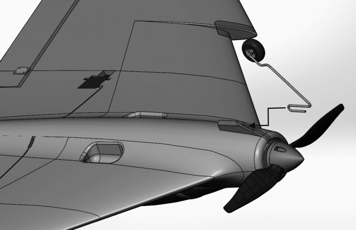
Then the plane were assembled finished.
Assembly the receiver and battery
3.1 Receiver installation
- The receiver has to be installed further aft in the fuselage. Check that the cables are long enough to allow the plugs and sockets to the connected outside the fuselage. The speed controller can be secured in the space under the canopy.
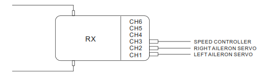
- Connect the left servo to CH1, right servo to CH2,Speed controller to CH3
3.2 Battery installationInstall the battery in the model as below pic,and fixed the battery with loop straps,this is very import,because this plane is an high performance Acro model,Loose battery maybe crashed the plane.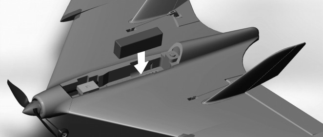 Fig. 1 LiPo charging instructions
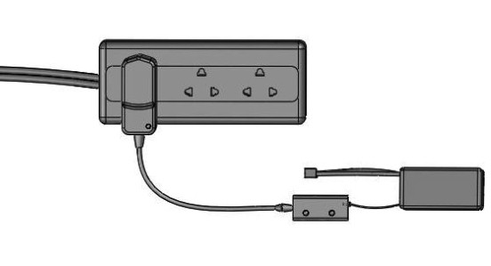
- Charge the LiPo battery by connecting the wall socket adapter (not included) to the balance charger. When power is supplied to the balance charger, connect the charge lead (usually white) of the LiPo battery to the balance charger.
- Always supervise charger while in use and avoid charging battery for extended periods of time (keep charge time under 1 hour and 30 minutes).
Checking the power system.
- Power on the transmitter with the throttle stick and trim at the “LOWEST” position then power up the aircraft.
- Hold the aircraft securely.
- Remove any loose objects such as cloths, tools, etc from the area in front of the model.
- Open the throttle (stick forward): the motor should now run and you should feel a strong air flow rushing out from propeller. Please do not bench test the unit for more than 10 seconds as there is no flowing air to cool the unit.
- Move the throttle stick back to the “LOWEST” position.
- Move the Elevator the plane will pitch up or pitch down.
- Move the Aileron the plane will roll right or roll left.
- Disconnect the battery from the electronic speed controller and then switch the transmitter off.
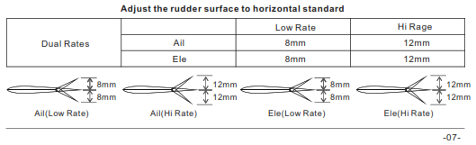
- After assembly and transmitter set up,confirm that the control surfaces are centered1, Verify the trims and subtrims on your transmitter are 02, Power up the model and leave the throttle at 03, Verify the control surface tips are mechanically centered.4, If you need to make an adjustment,rotate the clevis on the linkage to alter the linkage between the servo and the control horn.
Checking the model’s balance.
- Place the flight battery in its compartment without connecting.
- Mark the centre of gravity (CG) on both sides of the fuselage; the position is shown in the photo.
- Support the model at the marked points and allow it to hang freely. When correctly balanced the airplane will remain horizontal with the nose slightly down.
- If necessary, adjust the position of the flight battery to achieve the correct CG.
- Mark the battery location in the fuselage, so that you can be sure of positioning it correctly after recharging.
- Charge the flight battery and the model is ready for flight.
Test flying – Notes on flying the airplane.
- For the first flight you should wait for a relatively calm day with no more than a gentle breeze.
- A good flying site is a large, flat, open field; well away from trees, fences, high-tension overhead cables and other potentially dangerous obstacles.
- Carry out a complete check of the working systems.
- All control surfaces respond correctly.
- Adequate throttle response and battery voltage.
- Perform a range check if haven’t already.
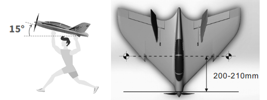
- We recommend that you ask an experienced modeler to help you initially; to give the model a fairly powerful hand-launch.
- The model must be launched directly into any existing wind.
- Switch the motor on, and launch the airplane strongly into the wind with the fuselage and wings leveled.
- Allow the F38 to fly straight and level initially; don’t try to turn it when it is close to the ground.
- Adjust the trims if necessary so that the model settles into a steady climb.
- Check the model’s response to control commands from the transmitter. You may need to increase or reduce the control surface travels once the model is back on the ground.
- Take the airplane up to a safe height and check its stalling speed.
- Keep the speed well up on the landing approach to avoid stalling.
- If you had to move the trims during the flight, correct the mechanical linkages before flying again. This allows you to re-centre the trims, so that full trim travel is available for subsequent flights.
F38 HORNET RC Assembly And Operation Instructions Manual – F38 HORNET RC Assembly And Operation Instructions Manual –
[xyz-ips snippet=”download-snippet”]