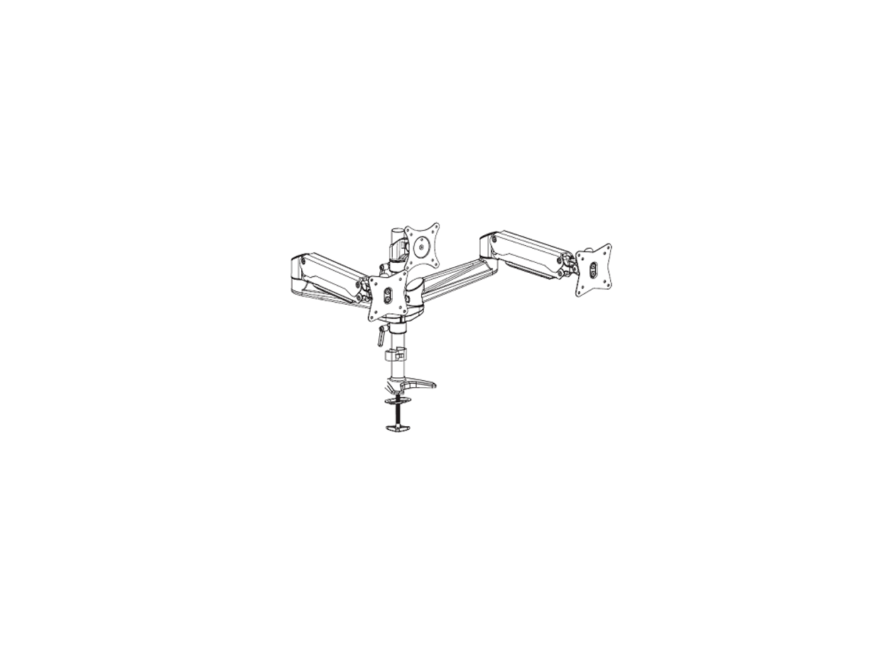
HUANUO HATS3 Gas Spring Aluminum LCD Monitor Desk Instruction Manual

IMPORTANT SAFETY INFORMATION
- Please read through these instructions completely before attempting installation. If you do not understand the instructions or have any concerns or questions, please contact customer service at [email protected]
- Check package contents against Supplied Parts and Hardware List to assure that all components were received Do not use damaged or defective parts. If you require replacement parts, contact customer service at [email protected]
- Not all parts and hardware included will be used.
- This product contains a high pressure gas spring, kre and percussion prohibited. Also it is strictly prohibited to dismantle without professionals. Please return to the manufacturer or hand over to professional agencies if the product is
- Do not use this product for any purpose or in any conkguration not explicitly speciked in this We hereby disclaim any liability for injury or damage arising from incorrect assembly, incorrect mounting, or incorrect use of this product.
Check the VESA Pattern of Monitor before the Installation
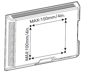
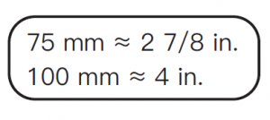 Minimum VESA Pattern: 75mm/3 in.(W) x 75mm/3 in.(H)
Weight Restrictions
 WARNING:
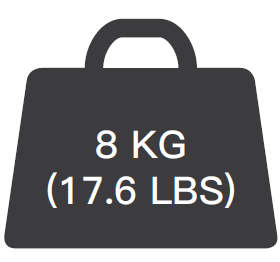 DO NOT exceed the maximum weight indicated. This mounting system is intended for use only within the maximum weights indicated. Use with products heavier than the maximum weights indicated may result in failure of the mount and its accessories, causing possible injury.
If your monitor weighs more, this mount is NOT compatible.
SUPPLIED PARTS AND HARDWARE

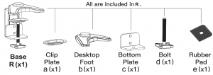
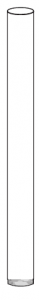 Pole Q(x1)

Note: The set screws [N] are spare screws which can be used if the preassembled set screws on the arms [W] and compression arms [U] are missing.
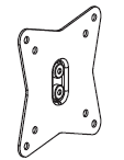

VESA Plate VESA Plate Compression Arm Supporting PartS (x2) T (x1) U (x2) V (x1)

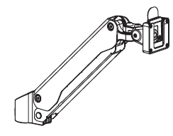
Extension ArmW (x4)

Line HookX (x2)
TOOLS REQUIRED NOT INCLUDED
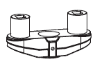
STEP 1 INSTAL THE BASE
A ) FOR CLAMP MOUNTING
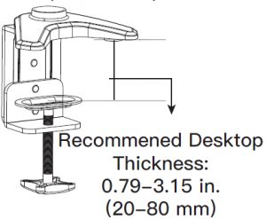
1 Measure the thickness of desktop

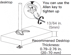
2 For desktop with thickness within 0.79-3.15 in. (20-80 mm)
2-1. Adjust the base according to the thickness of desktop

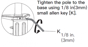
2-2. Connect the pole [Q] to the base [R]

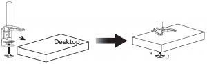
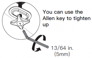
3. Secure the base assembly to the desktop
B For Grommet Mounting
1. Detach the base [R] entirely
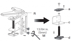
2. Connect the pole [Q] to the desktop foot [b]

3. Keep the rubber pad [e] and 4pcs preassembled bolts for next step when detaching the base

4. Install base plate [P] and rubber pad [e] to desktop foot with 4pcs bolts

Attach rubber pad [e] to bottom plate.
5. Install the pole assembly with bolt [d] and clip plate [a]

6. Secure the pole assembly to the desktop
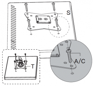
STEP 2 ATTECH THE VESA PLATES TO THE MONITORSFor Flat Screen Monitors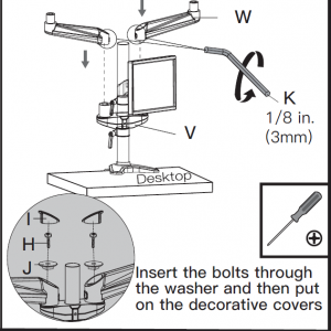
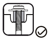
FOR COVERED MONITORS
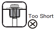
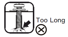
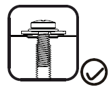
 When attaching brackets to the flat screen, be careful not to over tighten screws and be sure that screws do not bottom out in the mounting holes.
Step 3 Secure the Arm Assembly to the Pole Assembly
Step 3-1 Slide the locating ring [O], supporting part [V], locating ring [O] and monitor in sequence to the pole
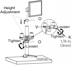
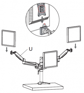
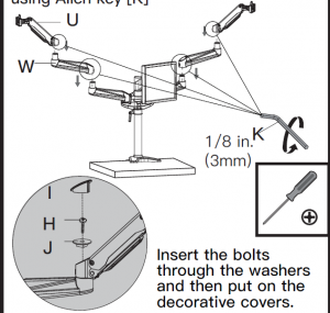
Step 3-2 Slide the two extension arms [W] to the supporting part [V] and tighten them using Allen key
If the monitors are 24in. or smaller
Attach the two compression arms [U] to the two extension arms [W] and tighten them using Allen key [K]
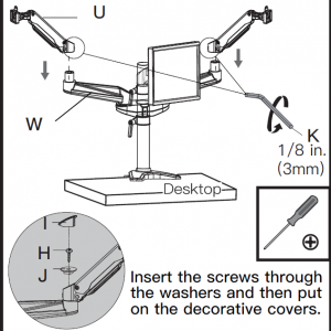
Secure the monitors to the compression arms [U]
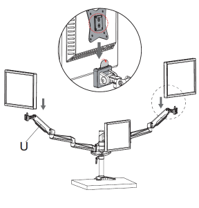
IF THE MONITORS IS LARGER THEN 24in.
Attach the other two extension arms [W] to the preassembled extension arms, then attach the compression arms [U] to the extension arms [W] and tighten them using Allen key [K]
Secure the monitors to the compression arms [U]
STEP 4 ADJUSTMENTS
Gas Spring Adjustment

NOTE: Turn clockwise to reduce tension for lighter monitors and counter-clockwise to increase tension for heavier monitors. Keep adjusting until monitor can keep still at any position

Be sure to keep the arm in horizontal position during adjustment or else, it would be difficult to adjust the mount.
Tilt and Swivel Adjustments

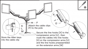
Step 5 Route the Cables
Read More About This Manual & Download PDF:
[xyz-ips snippet=”download-snippet”]