
Amaryllis
Installation Manual
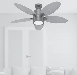
Model: 51191 Noble Bronze51192 Matte SilverFan weight ±2 lbs: 24.9 lbs (11.3 kg)
Congratulations on purchasing your new Hunter® ceiling fan!
The ceiling fan you purchased will provide comfort and performance in your home or office for many years. This instruction manual contains complete instructions for installing and operating your fan. We are proud of our work and appreciate the opportunity to supply you with the best ceiling fan available anywhere in the world.
We are here to help!
This Instruction Manual is designed to make installation as simple as possible. While working through this Instruction Manual, keep your smartphone or tablet nearby. We have added video links to help you through the more technical sections. If you are unfamiliar or uncomfortable with wiring, contact a qualified electrician. We also provide telephone support at 1.888.830.1326 or visit us at HunterFan.com.
![]() READ and SAVE These Instructions
READ and SAVE These Instructions


![]()
Warning
w.1 – To reduce the risk of fire, electrical shock, or personal injury, mount fan directly from building structure and/or an outlet box marked acceptable for fan support of 70 lbs (31.8 kg) and use the mounting screws provided with the outlet box.w.2 – To avoid possible electrical shock, before installing or servicing your fan, disconnect the power by turning off the circuit breakers to the outlet box and associated wall switch location. If you cannot lock the circuit breakers in the off position, securely fasten a prominent warning device, such as a tag, to the service panel.w.3 – To reduce the risk of electric shock, this fan must be installed with an isolating wall control/switch.w.4 – To reduce the risk of personal injury, do not bend the blade brackets when installing the blade brackets, balancing the blades, or cleaning the fan. Do not insert foreign objects in between rotating fan blades.w.5 – Chemical burn hazard. Keep batteries away from children. This remote contains a lithium button cell battery. If a new or used lithium button/coin cell battery is swallowed or enters the body, it can cause severe internal burns and can lead to death in as little as 2 hours. Always completely secure the battery compartment. If the battery compartment does not close securely, stop using the product, remove the batteries, and keep it away from children. If you think batteries might have been swallowed or placed inside any part of the body, seek immediate medical attention. Dispose of cells properly and keep away from children. Even used cells may cause injury.w.6 – Non-rechargeable batteries are not to be recharged. Exhausted batteries are to be removed from the product.
Caution
c.1 – All wiring must be in accordance with national and local electrical codes ANSI/NFPA 70. If you are unfamiliar with wiring, use a qualified electrician.c.2 – Use only Hunter replacement parts.This equipment has been tested and found to comply with the limits for a Class B digital device, pursuant to part 15 of the FCC Rules. These limits are designed to provide reasonable protection against harmful interference in a residential installation. This equipment generates, uses and can radiate radio frequency energy and if not installed and used in accordance with the instructions may cause harmful interference to radio communications.However, there is no guarantee that interference will not occur in a particular installation. If this equipment does cause harmful interference to radio or television reception, which can be determined by turning the equipment off and on, the user is encouraged to try to correct the interference by one or more of the following measures:
- Reorient or relocate the receiving antenna.
- Increase the separation between the equipment and receiver.
- Connect the equipment into an outlet on a circuit different from that to which the receiver is connected.
- Consult the dealer or an experienced radio/TV technician for help.
Caution: modifications not approved by the party responsible for compliance could void user’s authority to operate the equipment.This device complies with Part 15 of the FCC Rules. Operation is subject to the following two conditions: (1) This device may not cause harmful interference, and (2) this device must accept any interference received, including interference that may cause undesired operation.
This product conforms to UL Standard 507.
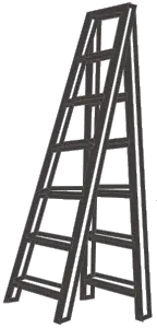
Here are the tools you’ll need to complete your installation:
![]()
Ladder Screwdriver
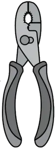
Pliers Wire Strippers
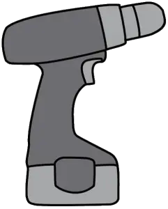
OPTIONALIf mounting to a support structure, you will also need these tools.
![]()
Drill 9/64” Drill Bit
© 2020 Hunter Fan Company7130 Goodlett Farms Pkwy, Suite 400Memphis TN 38016
Here is what comes in your box:
We recommend that you pull everything out of the box and lay it out. We have grouped the drawn components below with the hardware you’ll need for those parts. The screws below are drawn to scale to make it easier to identify what piece of hardware is needed to install each component.
Hunter Pro Tip:
Do not discard the hardware bags or mix parts from different bags. Make note of the symbol printed on each hardware bag. The symbols can be used to identify the appropriate hardware for each step.
![]() x2
x2
BAG Wood Screw
Washer x2 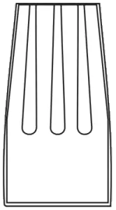 Wire Nut x4
For installing the hanger bracket and wiring the fan
Ceiling Bracket
Blade Arm x5
Blade x5
For installing the blades

Remote Control Remote Cradle Remote Receiver
Remote Components
BAG Spare Parts
For your convenience, you may receive extra fasteners.
 Extra downrod
x3 x2
BAG Light Kit Screw Short Light Kit Screw
 Motor
Motor
![]()
 Light Kit Assembly
![]()
![]() Switch Housing Plate
Switch Housing Plate
![]()
![]() Bulb x2
Bulb x2
![]() Globe
Globe
![]()
![]() Globe Retainer
Globe Retainer
For installing the light fixture
Note:Fan style may vary.
![]()
Find a part that is missing or damaged?Don’t take it back to the store. Let us make it right. Visit us at HunterFan.com or call us at 1.888.830.1326.
M3869-01 r122120
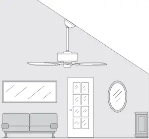
Choosing the Right Installation Location
You probably bought this fan with a location in mind. Let’s check below to make sure it is a good fit.
Check the room dimensions: Check the outlet box:
![]()
![]() You must be able to secure the fan to building structure or fan-rated outlet box.
You must be able to secure the fan to building structure or fan-rated outlet box.
Checking the Ceiling Angle:
Standard Mounting
If you have a flat ceiling:Hang your fan by a standard downrod. Some fans come with a shorter downrod for a Low Profile installation.
If you have an angled or vaulted ceiling:
- You will need a longer downrod. (sold separately at HunterFan.com)
- If your ceiling angle is greater than 34°, you will also need an Angled Mounting Kit. (Sold separately at HunterFan.com)
Angled Mounting
A little more information on Angled Mounting:
For optimum performance and appearance, a longer downrod should be used with your Hunter ceiling fan when installing on high or angled ceiling. If your ceiling is angled greater than 34° you will also need an Angled Mounting Kit. Longer downrods and the Angled Mounting Kit are sold separately at HunterFan.com.
Hunter Pro Tip:
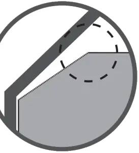
Determining if you need an Angled Mounting Kit:Fold on the dotted line. Place against edge againts the wall. Slide towards the ceiling.If the guide touches the wall but not the ceiling, you need an angled mounting kit.
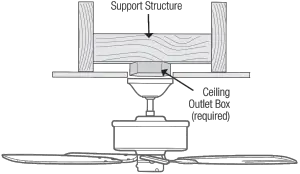
Installing the Ceiling Bracket
You have two options for installation. Pick which one works best for your location. Remove any existing bracket prior to installation. Only use the provided Hunter ceiling bracket that came in your fan’s box.
Do this first!
![]()
![]()
To avoid possible electrical shock, before installing your fan, disconnect the power by turning off the circuit breakers to the outlet box associated with the wall switch location.
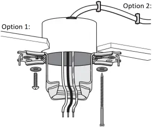
Option 1:Machine Screws
Use machine screws (provided with outlet box) and washers when securing to existing ceiling fan-rated outlet box. Make sure it is securely installed and is acceptable for fan support of 31.8 kg (70 lbs) or less.
ANGLED MOUNTING TIPFor angled ceilings, point opening toward peak.
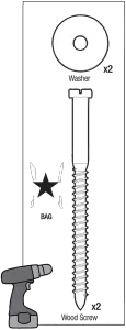
Option 2:Wood Screws
Use wood screws and washers (included) when securing to support structure with approved electrical outlet box. Drill 9/64” pilot holes in support structure to aid in securing ceiling bracket with hardware found in the ![]() hardware bag.
hardware bag.
Hunter Pro Tip:The machine screws are the ones that came with your outlet box.
Installing the Downrod
Follow below if you are using the downrod that came pre-assembled in your box. Need to install a longer or shorter downrod? Check out the guide at the end of this manual.
Remove the pre-installed setscrew so that the downrod can be inserted.
Hunter Pro Tip:The ground wire attached to the downrod is approximately 8 inches.
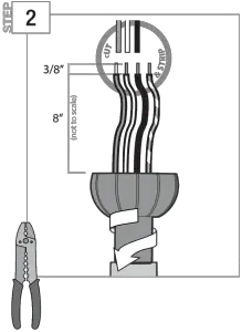
Pass all wires to one side of horizontal bar in downrod assembly. Hand tighten the downrod (at least 4–5 full turns) until it stops. Trim the wires coming from the fan so that 8-inches remain coming from the top of the downrod.
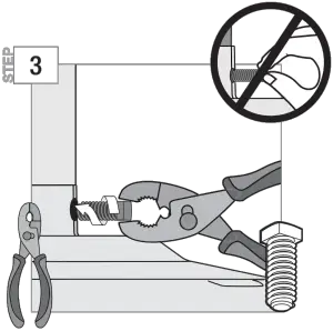
Tighten the setscrew with pliers. DO NOT HAND TIGHTEN.
![]()
FAN FALL HAZARD
To prevent SERIOUS INJURY or DEATH:
- ALWAYS tighten setscrew with pliers.
- DO NOT hand tighten setscrew.
- CHECK the setscrew is tight using pliers each time you change fan direction.
![]()
Hanging the Fan
NOTICETo prevent damage to fan, ALWAYS lift holding either the fan housing or the downrod.
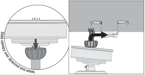
Place the downrod ball into the slot in the ceiling bracket.
Progress Check:Your fan should look like this.
Note:Fan style may vary.
Wiring the Fan
We know wiring is hard. Let’s make it easier.
Follow these steps to get your fan wired quickly and safely. Follow the route below that best matches your wall switch setup. If you are unfamiliar with wiring or uncomfortable doing it yourself, please contact a qualified electrician.
Hunter Pro Tip:
Here is how to connect the wires:Push the bare metal ends of the wires together and slide a wire nut over them. Then, twist the wire nut clockwise until tight.Give it a gentle pull to make sure none of the wires are loose.
Slide the remote receiver onto the top of the bracket.
WARNINGThe ceiling fan must be grounded. If the ground wire for the installation site is not present, immediately STOP installation and consult a qualified electrician.
WARNINGAll wiring must be in accordance with national and local electrical codes ANSI/NFPA 70. If you are unfamiliar with wiring or in doubt, consult a qualified electrician.
Hunter Pro Tip:
Have extra wiring?Turn the wires upward and push them carefully back through the hanger bracket into the outlet box. Spread the wires apart, with the grounded wires on one side of the outlet box and the ungrounded wires on the other side of the outlet box. Make sure that the wires are still attached to the wire nuts.
Connect the black (ungrounded) wire from the ceiling to the black wire from the receiver.
Connect the yellow wire from the receiver to the black wire from the fan.
Connect the white (grounded) wire from the ceiling to both the white wire from the receiver and the white wire from the fan.
Connect the blue wire from the receiver to the blue wire from the fan.
Connect the three grounding wires (green, green/yellow stripe, or bare copper) coming from the ceiling, downrod, and hanging bracket.
BAG
x4Wire Nut
Note:Fan style may vary.
DR19-01 r091420
Ceiling Bracket Downrod Hanging Fan Wiring Canopy Blades Light Control
Installing the Canopy
Fit the canopy in place as shown.
Lift the canopy into place so that the screw holes are aligned.
Hunter Pro Tip:
Let the tool do the work!A magnetic screwdriver will give you more visibility when securing the canopy.
Insert the two canopy screws found in the hardware bag.
BAG
x2Canopy Screw
Installing the Blades:
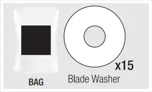
Put the blade washers, found in the hardware bag, onto the blade screws, found in the hardware bag. Then install the blade screws to secure each blade to a blade iron.Repeat x5
BAG
x15Blade Screw
BAG
x15Washer
Note:Fan style may vary.
IMPORTANT
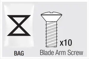
NOTE: The blade arms should be mounted with the ridge facing downward. Installing it incorrectly could result in your fan not functioning.
BAG
x10Blade Arm Screw
Lightly attach the blade arms to the motor with screws found in the hardware bag, then securely tighten after both screws are attached.Repeat x5
Ceiling Bracket Downrod Hanging Fan Wiring Canopy Blades Light Control
Assembling the Light Kit
BAG
2 of 3Light Kit Screw
Partially install two light kit assembly screws, found in the hardware bag, halfway into the motor housing as shown. It does not matter which two screw holes you choose.
Feed the 9-pin plug connector coming from the bottom of the motor housing through the center hole in the light kit assembly. Connect it to the plug connector found in the switch housing area of the light kit assembly. Make sure to line up the colored markings on the connectors.
Align the keyhole slots in the top of the light kit assembly with the partially installed assembly screws. Wrap the keyhole slots around the screws and twist counterclockwise.
BAG
1 of 3Light Kit Screw
Insert the third screw, found in the hardware bag, in place and firmly tighten all the three screws.
Note:Fan style may vary.
BAG
2 of 2Short Light Kit Screw
Carefully push all switch housing components into the switch housing, then install the switch housing plate using two short light kit assembly screws, found in the hardware bag.
WARNING
FAN FALL HAZARDMake sure all screws are tight to secure the light fixture.
Light Kit
Install a bulb into each of the sockets. When necessary, replace with bulbs of the same wattage.
Align the globe indentations with the globe retainer screw holes and carefully lower the globe into the globe retainer until it rests in place.
Repeat x2
Note:Fan style may vary.
Ceiling Bracket Downrod Hanging Fan Wiring Canopy Blades Light Control
Light Kit
Turn PowerON
WARNING
GLASS FALL HAZARDTo prevent SERIOUS INJURY or DEATH, make sure that glass is properly secured.
Lift the globe assembly and attach it to the upper switch housing using the four thumbscrews. Tighten all four screws securely by hand.
4 of 4Thumb Screws
Ceiling Bracket Downrod Hanging Fan Wiring Canopy Blades Light Control
Preparing the Remote
The remote control is already paired for use. For your convenience, a remote function card is packed in with your remote.
NOTICE
• Always purchase the correct size and grade of battery most suitable for the intended use.• Replace all batteries of a set at the same time.• Clean the battery contacts and also those of the device prior to battery installation.• Ensure the batteries are installed correctly with regard to polarity (+ and -).• Remove batteries from equipment which is not to be used for an extended period of time.• Remove used batteries promptly.
To access the battery compartment, remove the small Phillips head screw that secures the battery door to the transmitter assembly. The battery should be installed with the positive (+) side up. Replace with a CR2032 battery when necessary.
Remote Function Guide
Key Press Function+ Quick Press Light On/Off+ Long Press Light Dimming+ Quick Press Fan On/Off+ Quick Press Raise Fan Speed+ Quick Press Lower Fan SpeedLong Press Fan HighLong Press Fan LowLong Press + Dimming Mode On/Off
Turn PowerON
Installing the Remote Control Cradle
You have two options for installing the remote cradle.Choose which path works best for you.
Remove the cradle from the cradle bracket.
Option 1: Using Adhesive Strip
Separate the lining from the back of the adhesive strip on the cradle bracket.
Press the cradle bracket against the wall and hold firmly for 30 seconds.
Option 2: Using Screws
Choose your cradle installation location.
If you are installing into drywall, drill two 9/64 width holes using the cradle bracket as a guide. Gently hammer the included drywall anchors into the pre-drilled holes.
Slide the cradle onto the mounted bracket.
Ceiling Bracket Downrod Hanging Fan Wiring Canopy Blades Light Control
Reversing the Fan
Reverse Switch
Ceiling fans work in two directions: downdraft (counterclockwise rotation) and updraft (clockwise rotation). To change the direction of air flow, turn the fan off and let it come to a complete stop.The reversing switch is located inside the light fixture. It can only be accessed when the glass is removed. Slide the reversing switch to the opposite position. Restart the fan.
Updraft (clockwise rotation) creates a more indirect airflow. Updraft airflow is great for moving warm air downward.
Downdraft (counterclockwise rotation) creates a direct breeze and maximum cooling effect.
Troubleshooting
Fan Doesn’t Work
• Make sure power switch is on.• Check the circuit breaker to ensure the power is turned on.• Make sure the blades spin freely.• Turn off power from the circuit breaker, then loosen the canopy and check all the connections according to the wiring diagram.
Excessive Wobbling
• Make sure the blades are properly installed on the blade iron posts.• Turn the power off, support the fan carefully, and check that the hanger ball is properly seated.• Use the provided balancing kit and instructions to balance the fan.
Noisy Operation
• Make sure the blades are properly installed.• Check to see if any of the blades are cracked. If so, replace all of the blades.
Hunter Pro Tip:
Cleaning the FanUse soft brushes or cloths to prevent scratching.Cleaning products may damage the finishes.
Limited Lifetime Warranty
Hunter Fan Company grants this limited warranty to the original purchaser of this Hunter ceiling fan. This document can be found at www.HunterFan.com.Thank you for choosing Hunter!
How Can Warranty Service Be Obtained?
Proof of purchase is required when requesting warranty service. The original purchaser must present a sales receipt or other document that establishes proof of purchase. Hunter, at its sole discretion, may accept a gift receipt. To obtain service, contact Hunter Fan Company online or by phone.
www.HunterFan.com/Support/Contact-Us/1-888-830-1326
Please do not ship your fan or any fan parts to Hunter. Delivery will be refused.
What Does This Warranty Cover?
Motor — Limited Lifetime WarrantyIf any part of your ceiling fan motor fails during your ownership of the fan due to a defect in material or workmanship, as determined solely by Hunter, Hunter will provide you with a replacement fan free of charge.* The foregoing limited warranty applies only to the motor itself and does not apply to electronic controls – such as remote control transmitters, remote control receivers, or capacitors – used in conjunction with the motor. Such electronic control items are included in the one-year limited warranty below.
Other — One-Year Limited WarrantyExcept as otherwise indicated throughout this warranty, if any part of your Hunter ceiling fan fails at any time within one year of the date of purchase due to a defect in material or workmanship, as determined solely by Hunter, Hunter will provide a replacement part free of charge.*
Light Kits — Warranty May VaryLight kits are included in the one-year limited warranty. However, you may qualify for additional warranty coverage if your fan includes one of the following:
• LED Light Kits — Three-Year Limited WarrantyIf your LED light kit module (not including glass components) or LED bulb fails at any time within three years of the date of purchase due to a defect in material or workmanship, as determined solely by Hunter, Hunter will provide a replacement part free of charge.*
* If no replacement product/part can be provided for your fan, we will provide a comparable or superior replacement product/part at the sole discretion of Hunter.
What Does This Warranty NOT Cover?
Labor Excluded. This warranty does not cover any costs or fees associated with the labor (including electrician’s fees) required to install, remove, or replace a fan or any fan parts. There is no warranty for light bulbs (except where otherwise noted); remote control batteries; fans purchased or installed outside the United States; fans owned by someone other than the original purchaser; fans for which proof of purchase has not been established; fans purchased from an unauthorized dealer; ordinary wear and tear; minor cosmetic blemishes; refurbished fans; and fans that are damaged due to any of the following: improper installation, misuse, abuse, improper care, failure to follow Hunter instructions, accidental damage caused by the fan owner or related parties, modifications to the fan, improper or incorrectly performed maintenance or repair, improper voltage supply or power surge, use of improper parts or accessories, failure to provide maintenance to the fan, or acts of God (e.g. flood).ORIGINAL PURCHASER’S SOLE AND EXCLUSIVE REMEDY FOR A CLAIM OF ANY KIND WITH RESPECT TO THIS PRODUCT SHALL BE THE REMEDIES SET FORTH HEREIN. HUNTER FAN COMPANY IS NOT RESPONSIBLE FOR CONSEQUENTIAL OR INCIDENTAL DAMAGES, DUE TO PRODUCT FAILURE, WHETHER ARISING OUT OF BREACH OF WARRANTY, BREACH OF CONTRACT, OR OTHERWISE. Some States do not allow the exclusion or limitation of incidental or consequential damages, so the above limitation or exclusion may not apply to you.ANY IMPLIED WARRANTIES OF MERCHANTABILITY OR FITNESS FOR A PARTICULAR PURPOSE APPLICABLE TO THIS PRODUCT ARE LIMITED IN DURATION TO THE PERIOD OF COVERAGE OF THE APPLICABLE LIMITED WARRANTIES SET FORTH ABOVE. Some States do not allow limitations on how long an implied warranty lasts, so the above limitation may not apply to you.
How Does State Law Affect Warranty Coverage?
This warranty gives you specific legal rights. You may also have other rights which vary from state to state.
Downrod
If you need a different downrod length follow these steps:Follow steps 1-5 to remove standard downrod pipe
Follow steps 6-10 to reassemble with new downrod
WARNING
FAN FALL HAZARDTo prevent SERIOUS INJURY or DEATH:• ALWAYS follow the downrod assembly instructions exactly.• VERIFY the downrod is assembled correctly by firmly pulling on the hanger ball.• Pin must be reinserted to secure downrod assembly.
Here is another view of the downrod assembly unassembled.
report this adAssembled downrod should look like this
References
[xyz-ips snippet=”download-snippet”]