
HVAC EMS SAVINGS CALCULATOR USER GUIDE
GETTING STARTED
The current version of the HVAC Energy Management System (EMS) Savings Calculator can be downloaded from https://www.aesc inc.com/download/dukeenergy/. Prior to using the tool, we recommend that you close any active Excel workbooks. From the download page, right-click on the link for the HVAC EMS Calculator and save the file to your desktop. Due to the interactive, form-based nature of the calculator, you will need to make sure that macros are enabled in Excel.
The PDF output file from the calculator must be submitted with the Smart $aver application (Step 1) in order to receive an incentive payment. For application submissions and questions about the application process, contact us at [email protected].
MEASURE TOOL DESCRIPTION
The HVAC EMS Savings Calculator is an excel-based tool used to estimate savings due to the proposed implementation of EMS hardware. The calculator utilizes the combination of building and HVAC details based on the customer inputs to construct an energy model of the annual HVAC use.
This tool was developed to assist customers in identifying and estimating EMS saving opportunities. This tool currently estimates savings for the following measures:
- HVAC SchedulingHVAC scheduling reduces HVAC use during times when the spaces are unoccupied. This is typically accomplished with programmable timer settings internal to the EMS. During these times, the heating and cooling set points of the HVAC system(s) are reset to reduce heating and cooling loads. In addition to temperature resets, OA ventilation dampers are closed during unoccupied times.
- Optimum Start/Stop ControlsOptimum start / stop controls use an algorithm to determine the optimum time to start and stop HVAC systems to achieve the desired space conditions when the occupancy time begins. Correspondingly, the systems are also turned off to achieve the desired space conditions when the occupancy time ends.
- Demand-Controlled Ventilation (DCV)Demand-controlled ventilation allows HVAC systems to drastically reduce the amount of outside air they deliver to meet ventilation requirements. This is done by means of CO2 sensors placed throughout the facility. These sensors monitor indoor and outdoor CO2 levels and automatically adjust the OA dampers to keep the space CO2 levels within an acceptable range.
- Cooling/Heating Supply Air Temperature ResetSupply air temperature reset functions by adjusting the leaving air temperature of the heating or cooling coil (depending on operating mode) if less than full heating or cooling capacity is required by any of the zones served by the system.
- Integrated Dry-bulb or Enthalpy Economizer ControlIntegrated economizer control allows HVAC system with air-side economizers to take advantage of outside air whose overall energy content (based on dry-bulb temperature or enthalpy) is lower than that of the HVAC system return air.
- Chiller Supply Water Temperature ResetWater chillers typically operate with a fixed leaving evaporator water set point. Many hours of the year, the chiller could satisfy building loads while providing warmer water to the chilled water coils. Such a strategy generally increases HVAC fan energy at the air handlers, but reduces chiller energy (by means of increased operating efficiency) by a greater margin, saving energy.
- Chiller Condenser Water Temperature ResetWater-cooled chillers typically operate with a fixed entering condenser water set point. Most hours of the year cooling towers can be operated to provide cooler water. Condenser water reset controls the tower fans to produce cooler water when OA conditions allow, savings energy at the chiller.
- Night setbackNight setback reduces HVAC use by setting back thermostat temperature setpoints when the spaces are unoccupied. During these times, the heating and cooling set points of the HVAC system(s) are reset to reduce heating and cooling loads.
Appropriate Use of the Tool
EMS Savings Calculator can be used for facilities with the characteristics shown in Table 1.
Table 1: EMS Savings Calculator Common Features
| Description | Measure Feature |
| States | · Ohio· Indiana· Kentucky· North Carolina· South Carolina· Florida |
| Locations | · TMY3 Weather Stations |
| Building Type | · Small office· Large office (high-rise)· Retail· Manufacturing· Restaurant· Hospital (inpatient)· Hotel· School K-12· College/University |
| Operating Hours | · Monday – Friday, 8am – 5pm· Monday – Friday, 7am – 7pm· Monday – Friday, 24 hours per day· Monday – Saturday, 8am – 5pm· Monday – Sunday, 8am – 5pm· Monday – Sunday, 24 hours per day
· Monday – Sunday, 9am – 9pm · Monday – Sunday, 11am – 11pm· Monday – Friday, 6am – 8pm, Saturday and Sunday, 8am – 6pm· Monday – Saturday, 10am – 9pm· School (Monday – Friday, 8am – 5pm, closed in June and July) |
| HVAC System Types | · Single zone, constant volume (CV) system· Multiple zones, CV, single duct with zone reheat system· Multiple zones, variable air volume (VAV), single duct with zone reheat system· Multiple zones, CV, dual duct system· Multiple zones, VAV, dual duct system· Multiple zones, CV, multi-zone system |
Applicable Types of Equipment and size Covered by the Tool
EMS Savings Calculator covers the size and capacities of HVAC systems described in Table 2.
Table 2: Equipment Coverage Matrix
| Description | Description | Description |
| HVAC Cooling System Types | · Air-cooled chiller· Water-cooled chiller· Air-cooled DX· Absorption Chiller | Cooling system efficiency should be entered in kW/ton for all except for absorption chiller in COP. |
| HVAC Cooling System Types | · Natural draft boiler· Forced draft boiler· Condensing boiler· Furnace· Electric resistance· Heat pump | If electric resistance is selected for single duct with electric reheat systems, the tool defaults natural draft boiler for preheat. |
| HVAC Cooling System Types | · On 24/7· On 24/5· On 1 hour before and after building operating hours· On 2 hours before and after building operating hours· Optimum Start/Stop | N/A |
| HVAC Cooling System Types | · Minimum
· Dry-bulb · 100% outside air |
Tool assumes minimum outside air intake at 15% of total supply CFM |
MEASURE TOOL USE
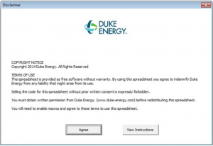
Tool inputs are done either by selecting predefined dropdown options or entering numerical values as prompted by the tool. When a user opens the calculator, a popup window will show as below. Users must first agree to the term of conditions by selecting the “Agree” button.
Inputs window is divided into two sections. First section on the left pertains to facility information and second section on the right includes existing HVAC equipment, plant, and proposed measure information. Refer to tables below for input details.
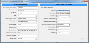
Table 3 – Site/Facility Inputs
| Input Name | Description / Purpose |
| Duke Electric Account Number | Enter the customer’s Duke Energy electric account number. |
| Customer Name | Enter the name of company or facility. |
| Site Address | Enter address of the facility |
| State | Select state from pull down. |
| Nearest Weather Station | Select location closest to the project site. Weather file associated with the location is used when calculating the savings |
| Building Type | Select building type from pull down. Note that small office represents a single up to three-story office building with conditioned area less than 100,000 sq. ft. Large office represents a high-rise office building with conditioned area greater than 100,000 sq. ft. |
| Square Footage | Enter square footage of the facility. Do not enter decimals (whole numbers only). |
| Number of Floors | Enter the number of floors. Do not enter decimals (whole numbers only). |
| Operating Hours | Select operating hours from pull down. |
| Actual # of Occupants | Enter the number of occupants in the building if it differs from the default value shown next to “Default # of Occupants”. |
| Lighting Types | Select the lighting type from pull down. Examples of old, standard, and high efficiency light fixtures are following: Old: T12, HPS, magnetic ballasted fixtures, etc. Standard: T8, T5, metal halide, etc. High efficiency: LED, induction, ceramic metal halide, etc. |
Table 4 – HVAC Inputs
| Input Name | Description / Purpose |
| HVAC Type | Select existing HVAC type from pull down |
| HVAC Schedule | Select existing HVAC equipment operating schedule from pull down. |
| Night Setback | Select yes if the both cooling and heating temperature setpoints are setback at night. |
| State | Select state from pull down. |
| Thermostat Cooling Setpoint | Enter current cooling setpoint temperature at the thermostat in °F. Do not enter decimals (whole numbers only). |
| Thermostat Heating Setpoint | Enter current heating setpoint temperature at the thermostat in °F. Do not enter decimals (whole numbers only). |
| Supply Air Temperature Strategy | Select if supply air temperature is reset or fixed in the existing system from the pull down. |
| Cold Deck Setpoint | Enter current cold deck setpoint temperature in °F. Do not enter decimals (whole numbers only). Default cold deck setpoint is 55 °F. |
| Hot Deck Setpoint | Enter current hot deck setpoint temperature in °F. Do not enter decimals (whole numbers only). Default cold deck setpoint is 95°F for hot water coil and 120°F for furnace. |
| Economizer | Select exiting economizer type from pull down. |
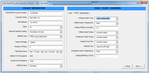
Table 5 – Plant Inputs
| Input Name | Description / Purpose |
| Cooling System Type | Select existing cooling system type from pull down. |
| Chilled Water Temperature | Select if chilled water temperature is reset or fixed in the existing system from the pull down. |
| Cooling Efficiency | Enter existing cooling system efficiency in kW/ton or COP for absorption chiller. |
| Chilled Water Pumps | Select if existing chilled water pumps are constant speed pumps or variable speed pumps from the pull down. |
| Condenser Water Pumps | Select if existing condenser water pumps are constant speed pumps or variable speed pumps from the pull down. |
| Cooling Tower Fan | Select if existing cooling tower fans are constant speed fans or variable speed fans from the pull down |
| Heating Type | Select existing heating system type from pull down. |
| Condenser Water Temperature | Select if condenser water temperature is reset or fixed in the existing system from the pull down. |
| Heating Efficiency (COP) – field enabled only when heat pump is selected | Enter heating efficiency in COP if heat pump was selected for the heating system. |
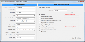
Under “Measures” tab, enter the project cost and select the EMS measures proposed from the list. The project cost should include all equipment, taxes, and external labor, but should not include the cost of any internal labor. Please note that tool will identify measures that are not applicable to the existing system or schedules in the “Notes” section. The tool will also identify measures that are, or may be, included in the prescriptive incentive program and are not eligible for customized incentives. Please see below for an example. Once all information is entered, select “Calculate” button on the bottom right corner of the Inputs window. The tool will then calculate savings based on the information entered and display a pdf report.
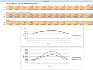
Tool Outputs – Savings Summary
The following table describes the tool outputs.
Table 6- Measure Energy Savings and Incentive
| Name | Description / Purpose |
| Baseline, kW | Estimated monthly maximum on-peak demand of the existing HVAC system and fans (based on hourly average between 12pm and 6pm) |
| Proposed, kW | Estimated monthly maximum on-peak demand of the proposed HVAC system and fans (based on hourly average between 12pm and 6pm) |
| Baseline, kWh | Estimated monthly energy use of the existing HVAC system and fans |
| Proposed, kWh | Estimated monthly energy use of the proposed HVAC system and fans |
| Savings, kW | Estimated monthly on-peak demand savings for the selected measures (difference between baseline and proposed) |
| Savings, kWh | Estimated monthly on-peak demand savings for the selected measures (difference between baseline and proposed) |
Tool Outputs – Notes and Error Messages
During use of the tool, the “Measures” tab may display one or more of the following notes:
| Note | Description / Purpose |
| Measure is not applicable | The selected measure is not compatible with the building, plant, or HVAC system specified and will not be used to determine savings |
| Need to install economizer | This measure can only be used with systems that include an economizer |
| Please select only one economizer measure | Only one of the economizer measures can be specified during a single run of the EMS calculator. |
| Measure is prescriptive | This measure is covered by the prescriptive program and cannot be used without selecting one or more applicable nonprescriptive measures. |
| Measure may be applicable | This measure is, or may be, covered by the prescriptive program. You can calculate savings using the EMS calculator, but please be aware that final eligibility will be determined prior to payment of any customized incentives. |
If errors are encountered during use of the tool, you may see one of the following messages: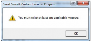
This indicates that you have not selected any measures or you have only selected measures that are not eligible due to your Facility, HVAC, or Plant inputs. Please review and correct your inputs or select one or more eligible measures.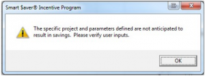 This indicates that the specific combination of inputs that you have provided will result in any energy savings. Please review your inputs to ensure that they accurately represent your facility.
If you believe that your measure will result in energy savings, please pursue a different savings methodology (ex: Building HVAC Modeling Software) to determine the expected savings.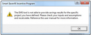 This indicates that the inputs defined will result in savings too large for this tool to accurately identify. Please review your inputs to ensure that they accurately represent your facility. If the error persists, please pursue a different savings methodology (ex: Building HVAC Modeling Software) to determine the expected savings.
HVAC EMS Savings Calculator User Guide – HVAC EMS Savings Calculator User Guide –
[xyz-ips snippet=”download-snippet”]