HYDRO GUARD Reverse Osmosis System Installation Guide
| LEGEND | |
 |
CAUTION / WARNING |
| EYE PROTECTION | |
 |
ELECTRICAL WARNING |
 |
FRAGILE |
![]() WARNING: READ ENTIRE I¥IANUAL. FAILURETO FOLLOWALL GUIDES AND RULES COULD CAUSE PERSONALINJURY OR PROPERTY DAMAGE.
WARNING: READ ENTIRE I¥IANUAL. FAILURETO FOLLOWALL GUIDES AND RULES COULD CAUSE PERSONALINJURY OR PROPERTY DAMAGE.
Check with your state and/or local public works department for plumbing codes. You must follow their guides as you install the Water Filtration system.
NOTE: Failure to comply with these installation instructions will void the product Warranty, and the installer wiII6e responsible far any service, repair ardamages caused thereby.
![]() WARNING: DO NOT USEWITH WATERTHAT IS MICROBIOLOGICALY UNSAFE OR OF UNKNOWN QUALITY WITHOUT ADEQUATE DISINFECTION BEFORE OR AFTER THE SYSTEM.
WARNING: DO NOT USEWITH WATERTHAT IS MICROBIOLOGICALY UNSAFE OR OF UNKNOWN QUALITY WITHOUT ADEQUATE DISINFECTION BEFORE OR AFTER THE SYSTEM.
INITIAL INSPECTION
TOOLS & MATERIALS NEEDED FOR NORMAL INSTALLATION:
- Cordless Drill
- Carbide grinding burr
- 1/4″(6 mm) drill bit
- 7/16“(J 1 mm) drill bit
- 1/2’13mm)andS/8’16mm)open-end wrenches (or adjustables)
- Phillips screwdriver
- Flashlight or droplight
- Teflon tape
- Protective eye wear (i.e. goggles)
If the above tools are not available, conrocr your local dealer/distributor for assistance.
WATER FILTRATION SYSTEM INCLUDES:
- Filtration system“-(3 Stage and 4 Stage available )
- Faucet – (with mounting hardware)PARTS (already pre-installed in system)
- Connection Tubing – (Pre-installed)
- SHOKBLOK – (Pre-installed)ACCESSORIES (Included in installation packet)
- Feedwater Adapter
- Ball Valve
![]() WARNING!! The following conditions for feed water supply must be met or Warranty will be void.
WARNING!! The following conditions for feed water supply must be met or Warranty will be void.
- Unit MUST be connected to a municipal or well water source that is treated and tested on a regular basis to insure water is microbiologically safe
- Operating temperatures:Maximum: 105° F (40.6° C)Minimum: 33° F (0.US° C)
- Inlet Pressure MUST NOT EXCEED 80 PSI (5.6 kg/cm2)
 CAUTION!! DO NOT ALLOW SYSTEM TO FREEZE. The membrane always contains water and will be destroyed if frozen.WARNING!! DO NOT PLUMB SYSTEM TO HOT WATER. This will damage filters and void the Warranty and manufacturer’s responsibility
 - Operating pressure:Maximum: 80 PSI (5.6 kg/cm2)Minimum: 40 PSI (2.95 kg/cm2)This drinking water system is designed to operate at a water pressure in the range of: 40 to 80 PSI (2.95 kg/ cm2 to 5.6 kg/ cm2).
- At pressures lower than this, the quantity as well as quality will be reduced.
- At higher pressure, severe, damage to the system may result.
A pressure regulator MUST be installed on the feed water source, which reduces the water pressure coming into the system.
WARNING!! warranty voided and manufacturer assumes no responsibility for damage to system or property if pressure exceeds 80 PSI.
- Turbidity: <5 NTU
- pH: 4 to J 1
- Sulfide, Iron and Manganese: less than 0.01 ppm.
- Chlorine In Water Supply: less than 2 ppm.
- Water Supply pH Limits: 4-11.
- Turbidity: NTU Max.
RECOMMENOATJON: lf your water hardness exceeds 7 grains per gollon, or I20 PPE you may wish to putcbose a wotet softened. Contact your local dealer of distributor for pricing and availability.
- Recommended Total Dissolved Solids (TDS) NOT TO EXCEED 2000
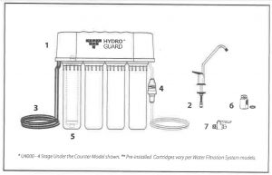
PLUNBING SCHENATIC
PLUMBING SCHEMATIC FOR 3 & 4 STAGE UNDER COUNTER FILTER SYSTEMS
(U4000 – 4 Stage Under the Counter Model shown),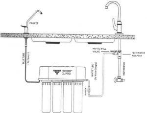
NOTE: the water ñlvation system may be mounted to the side of the sink cobinet o set on the hoot of the sick cabinet near the focet tube to maximize flow tate
PRE &FAUCETINSTALLATION
IMPORTANT!! PLEASE READ, FOLLOW AND SAVETHIS INSTRUCTION MANUAL.
- PRE-INSTALLATION PROCEDURE
- This unit includes a standard sink top fa ucet without an air-gap. In localities where plumbing codes require installation of an a -9ap, contact your local distributor to obtain a code approved drain line adapter
- The water filtration system may be mounted to the side of the sink cabinet or set on the floor of the sink cabinet. It must be positioned to allow access for service and filter changes. The assembly should be relatively near the faucet to maximize flow rate. (See DIAGRAM A for a positioning example)
- The faucet should be positioned to allow a free flow pattern into the sink. It must be positioned to allow ready access to the mounting hardware under the sink. (See DIAGRAM A fora positioning example.)
- FAUCET INSTALLATIONCAUTION!! Extreme care must be taken in drilling the hole for the sink-top faucet. The surface material of most sinks is extremely hard and brittle and can be easily chipped or cracked. If you are uncomfortable performing the following procedure it is recommended that your local distributor or experienced plumber be consulted for techniques, installation or other assistance. The system’s manufacturer accepts no responsibility for sink top damage resulting from system installation. EXTREME CAUTION SHOULD BETAKEN WITH GRANITE, MARBLE AND LIKE MATERIAL
CAUTION!! Before grinding or drilling put on appropriate eye protection (i.e. goggles)to protect yourself from porcelain or metal chips.CAUTION!! To avoid damaging the sink, consult a qualified plumber or installer for drilling procedures. Special drill bits may be needed for porcelain or stainless steel.WARNING: Many homes are electrically grounded through the plumbing. To protect yourself tfrom serious injury or fatal shock, use a battery-powered hand drill only to make the hole. DO NOT USE AN ELECTRIC DRILL.
- BEFORE DRILLING: Check under the sink in the area that you plan to install the faucet and make sure that there is a flat surface to secure the mounting hardware. A flat space of approximately 2 inches in diameter is needed.RECOMMENDATION: Before drilling or grinding mask off the immediate area surrounding the grinding/drilling location preferably with duct tape or if duct tape is unavailable masking tape may be used. This procedure should help prevent scratching of the sink surface.
- REMOVE EVERYTHING FROM INSIDE THE SINK AND SURROUNDING AREA. Place paper towels in the sink to catch the shavings from the grinding and drilling.
- Using a cordless drill with a carbide grinding burr, gently grind away enough porcelain or enamel to more than accommodate the 7/16″ (11 mm) drill bit. Approximately the size of a dime. Enough surface material must be removed to expose the base metal.CAUTION!! Porcelain or enamel must be completely removed in the drilling area to prevent immediate dulling of drill bit.
- Remove everything from under the sink.
- Place newspaper or paper towels directly under drilling location in order to catch the drill shavings.
- Using the 1/4″ (6 mm) drill bit, drill a centering or pilot hole in the center of the desired faucet location.NOTE: this centering/pilor hole will make it easier for the 7/16″ (11 mm1 drill bit to cut through the sink. Operate the drill slowly and carefully—Especially when the drill bit is about to penetrate the metal. Otherwise, damage to sink may occur. Use lubricating ail to keep the drill bit cool while drilling.
- Discard paper towels and newspaper used in sink and below sink. Be very careful not to drop any shavings in sink or on the floor as they will oxidize and stain surfaces very quickly. HELPFUL H1NT: If you notice any rust spots from dropped shavings you should be able to get rid of them by scrubbing them with a cleaning chemical.
- Cover the drilled hole with your finger BE VERY CAREFUL NOT TO CUT YOURSELF ON SHARP EDGES! Rinse sink then scrub with cleaner to prevent any rusting from shavings and to prepare for faucet installation. Plug hole again while rinsing off cleaner. Hole must be plugged in order to avoid water dripping below into sink cabinet, which may cause damage
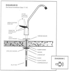
- Remove faucet from package.For steps 11-14 refer to DIAGRAM B on Below.
- Slip the small, thin rubber gasket over the faucet shank. Next slip the chrome trim plate (escutcheon plate) over the faucet shank. Finally, slip the large, thin rubber gasket over the faucet shank.
- Take the faucet spigot and insert it into the faucet base in the hole next to the faucet handle. Push the faucet spigot in until it stops.
- Place the faucet shank complete with only hardware installed in step 11 though the drilled hole.
- From under the sink slip the large, black plastic, locating washer over the faucet shank. Next, slip the lock washer over the faucet shank followed by the thin Chrome nut.
- While holding the faucet assembly above the sink tighten the chrome nut below the sink with an adjustable Tighten the chrome nut until the faucet assembly does not move.
![]() CAUTION!! DO NOT OVER TIGHTEN THE CHROME NUT. Overtightening can cause damage to the sink or faucet assembly.
CAUTION!! DO NOT OVER TIGHTEN THE CHROME NUT. Overtightening can cause damage to the sink or faucet assembly.
DIAGRANS B, C, D, & E
FEEDWATER ADAPTER
![]() CAUTION!! For your safety and protection, do not use where water is microbiologically unsafe or of unknown quality. The water supply to your system MUST be from the COLD WATER LINE! Hot water will severely damage your filtration system!
CAUTION!! For your safety and protection, do not use where water is microbiologically unsafe or of unknown quality. The water supply to your system MUST be from the COLD WATER LINE! Hot water will severely damage your filtration system!
- Turn off cold ‘water supply to the sink using the supply valve located under the sink.NOTE:lv some cases the supply valve may leak of may not work at all. If this happens tuIn out the wotet at the main woter shut out for the entire house. In exveme coses the house shut off valve does not work, 1{this happens shut t)e wotet oltot the street and teploce the detective valves immediotely. Locote the t/pe ofshut off valve you hove under your sick and follow thot step for connecting the Leedwoter.
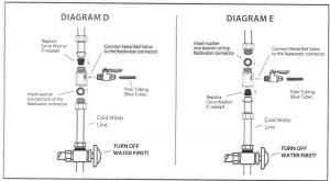
- Some shut of valves have an extra port for an icemaker hookup.You will not need the feedwater adapter for this type of installation. (See DIAGRAM C)
- On some shut off valves you can install the feedwater adapter directly to the valve. Slip the black washer into the feedwater adapter. Tighten feedwater adapter to the valve with an adjusable wrench. Tighten until snug. Insert the 1/4″ nylon elbow fitting into the feedwater adapter. TIGHTEN BY HAND ONLY! DO NOT OVERTIGHTEN! ( See DIAGRAM D )Most under sink shut off valves have a built in smooth or corrugated riser going up to the faucet. (Refer to DIAGRAM E for help with this type of valve.)Secure an adjustable wrench to the fitting on the cold water side of the sink faucet –NOT THE WATER SYSTEM FAUCET! Secure another adjustable wrench to the smooth/ corrugated riser line nut. Gently undo the riser line from the sink faucet. Do not be alarmed! There will be water left in the line—this is normal. However, if the flow does not stop you probably haven’t shut the water off properly. (See the NOTE in Step # 1, Section # 3 if you need help with water shut off)
- Insert the black rubber washer into the feedwater adapter. Screw the adapter onto the fitting coming from the cold water side of the sink faucet. Using two adjustable wrenches tighten the feedwater adapter to the cold water line. Take extreme care not to twist or damage the connection to the cold water connection.CAUTION!! Tightening the connector improperly to the faucet could cause irreparable damage to the faucet.
- Connect the riser from the water shut off valve to the feed water adapter. Ensure that the cone washer on the riser tube is in good condition. With one adjustable wrench on the feed water adapter and another adjustable wrench on the riser nut connect the riser to the feed water adapter. DO NOT OVERTIGHTEN! This can cause damage to the riser connection.
- Insert the 1/4”‘ nylon elbow fitting into the feedwater adapter. TIGHTEN BY HAND ONLY! DO NOT OVERTIGHTEN!
UNIT PLACENENT & TUBING
WATER FILTRATION SYSTEM PLACEMENT AND MOUNTING
- Determine if mounting of the water filtration system is necessary or desired. The system does not need to be mounted on the wall of the cabinet if there is room for it to sit on the However, if it is mounted to the side of the cabinet it is easier to change the filters and does not take up floor space.IMPORTANT!! Be very careful not to kink any of the tubing on the water filtration system.If tubing is kinked the tubing can rupture and leak.
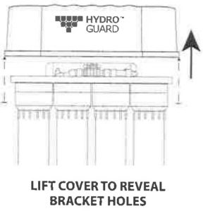
- Position the system on the wall at the desired mounting location 2 – 3 inches from base of cabinet. Using the bracket holes on the back of the bracket, mark on the wall with a pencil where the screws need to be inserted
- Set the system aside.
- Screw the two (2) Phillip head screws (supplied in the installation packet) into the wall at the marked positionsNOTE: Let the screw heads protrude from the wall enough to hang the filtration system safely.
- Mount the water filtration system onto the screws.
LIFT COVER TO REVEAL BRACKET HOLES
TUBING CONNECTIONS
IMPORTANT!! Be very careful not to kink any of the tubing on the water filtration system. If tubing is kinked the tubing can rupture and leak
CONNECTING THE SYSTEM:(BLUE TUBING – From system faucet port. This is from port labeled faucet)
- Connect the blue tubing to the faucet by slipping the 1/4” chrome nut over the tubing followed by the nylon ferrule.NOTE: It is not necessary to hove a 1/4”nylon insert in this line as it would restrict the how th ough the faucet.
- Push the blue line all the way into the faucet stem and tighten the chrome nut. DO NOT OVERTIGHTEN!!
CONNECTING THE FEEDWATER: (WHITE TUBING – From System inlet port)
- chrome nut over the end of the tubing from the metal ball valve with blue lever.
Then insert the end of the extra white tubing into the barb of the ball valve on the feed water adapter. Tighten the chrome nut securely. DO NOT OVERTIGHTEN
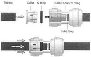
TUBING & QUICK CONNECT FITTINGS
CONNECTING THE FEEDWATER
- If you have the connection for the icemaker tee as in Step # 2 of Section ¢ simply slide the 1/4“chrome nut over the blue tubing. Slip the nylon ferrule over the blue tubing and insert the 1/4” nylon insert into the tubing end. Insert tubing into the cold water shut off valve and tighten securely.
DO NOT OVERTIGHTEN!
HOW TO MAKE QUICK CONNECT FITTINGS CONNECTIONS
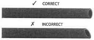
- CUT THE TUBINGCut the tube cleanly and squarely. Ensure that the tube has a smooth outside diameter without any burrs, chamfers or score marks prior to inserting it into the fitting. Tubing that has not been cut properly can cause drips and leaks.
- INSERTTUBINGPush the tubing through the collet and o-rings until it bottoms out against the tube stop. The collet holds the tube in place and the o-ring provides a leak resistant seal. If you need to remove the tubing always re-cut before connecting tubing again. Scores on tubing can cause failure.
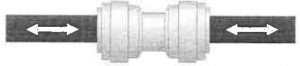
- INSPECT AND TESTPush and pull the tubing toward and away from the fitting to ensure that it has been installed properly. Test and inspect the installation for any leaks.
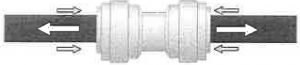
- TUBE REMOVALRelieve pressure from the tubing and fitting. Push the collet flange against the fitting body while pulling the tubing away from the fitting to release it.
![]() CAUTION!! IT IS RECOMMENDED THAT TUBING AND QUICK CONNECTION FITTINGS INSTALLATIONS ARE INSPECTED A MINIMUM OF ONCE PER YEAR AND PARTS REPLACED AS NEEDED.
CAUTION!! IT IS RECOMMENDED THAT TUBING AND QUICK CONNECTION FITTINGS INSTALLATIONS ARE INSPECTED A MINIMUM OF ONCE PER YEAR AND PARTS REPLACED AS NEEDED.
SYSTEN START UP & FLUSHING RO SYSTEN
SYSTEM START-UP
- With all connections complete, turn on the cold water supply to the filtration systemIMPORTANT!! The Water Filtration Systems Main Water Shut Off valve (indicated by the bright oronge tag at the side of the unit) must be open. This means the blue handle on the valve must be in the horizontal position.
- Immediately check entire water filtration system for leaks. If you notice any leaks turn off cold water supply and fix the leak.
FLUSHING THE WATER FILTRATION SYSTEMS
- Open the filtration system faucet and let water run for 5 minutes.
![]() CAUTION!! If installing the unit in new construction, ensure that house plumbing is flushed thoroughly before opening the water supply valve
CAUTION!! If installing the unit in new construction, ensure that house plumbing is flushed thoroughly before opening the water supply valve
![]() WARNING!! Discard all unused parts and packaging material after installation. Small parts remaining after the installation could be a choke hazard.
WARNING!! Discard all unused parts and packaging material after installation. Small parts remaining after the installation could be a choke hazard. BALL VALVE MAIN WATER SHUT-OFF
FILTER REPLACEMENT
FILTER REPLACEMENT INSTRUCTIONSiG4000 – 4 5taqe Under the Counter Model shown).
Step 1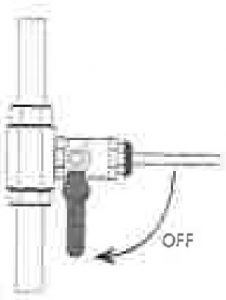
TURN WATER OFFTurn Ball Valve Main Water Shut-Off Blue handle to vertical position
Step 2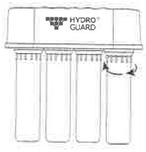
UNSCREW HOUSINGUnscrew to the lett to open housing
Step 3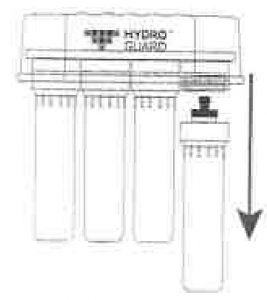
REMOVE FILTER & HOUSINGreveal filter. Pull fiIter down into housing and remove
Step 4 REPLACE FILTERPlace New Cartridge in Housing making sure 0-Ring seals are on top. Bottom of cartridge should seat in cup at bottom of Housing Note: rinse housing thoroughly and scrub with soft brush betore reinstalling new cartridge
Step 5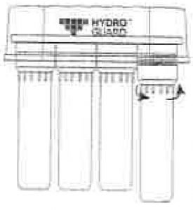 SCREW BACK HOUSINGRaise Housing and screw on towards right by hand
Step 6
TIGHTEN FILTERHand tighten to the right unti| snug connection is made DO NOT OVERTIGHTEN
Step 7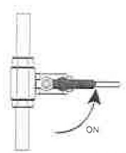
TURN WATER BACK ONTurn Ba|l Valve Main Water Shut-Off Blue handle to horizontal position
Step 8 Section 8 and 9 on page belowFollow Steps for System Start Up & Flushing the R.O. System
TROUBLESHOOTING
| NOT ENQUGH WATER | |
| POSSIBLE | CAUSE / SOLUTION |
| Feed water valve is plugged or closed. | Open valve or unclog. |
| Sediment/Carbon prefilter or Carbon Post Filter is clogged. | Replace Filters. |
| Low incoming water pressure. | Incoming water pressure must be above 40 PSI. Instali a Booster Pump or Permeate Pump. |
| LOW WATER PRESSURE FROM DISPENSING FAUCET | |
| Carbon Post Filter is clogged | Replace Post Filter. |
| The Faucet is out of adjustment or faulty | Repair or replace Faucet |
| TASTES AND ODERS IN PRODUCTION WATER | |
| Carbon Post Filter is exhausted | Replace Filter |
| Dissolved gases in feed water. | Pre-treat feed water to remove gases |
| Increase in ProductWaterIDS | See next table: High TOS in Product water and drain water lines are reversed CAUSE / SOLUTION Section. |
| FAUCET LEAKS OR DRIPS | |
| Water leaks from facuet spout | Adjust faucet by turning the tee bar located under the handle Water leaks from faucet spout. to provide a small amount of free play in the handle when shut off. Should this not work, repair or replace the faucet. |
| Leaks from beneath the handle | Repair or replace the faucet. |
| NO WATER | |
| Water is shut off at stop value | Open main stop value. (see diagram on page beow) |
SERVICE RECORDS
DATE
| CARTRIDGE | CARTRIDGE | CARTRIDGE | CARTRIDGE |
| #1 | #2 | #3 | #4 |
LIABILITY & WARRANTY
LIABILITY
![]() WARNING!!! The installer is responsible for any leaks resulting from installation of tubing or related fittings. THE INSTALLER MUST CHECK OVER THE ENTIRE SYSTEM COMPLETELY WHILE UNDER PRESSURETO ENSURE SYSTEM IS NOT LEAKING AND FUNCTIONING PROPERLY. Liability resulting from failure to check for leaks under pressure is the sole responsibility of the installer.
WARNING!!! The installer is responsible for any leaks resulting from installation of tubing or related fittings. THE INSTALLER MUST CHECK OVER THE ENTIRE SYSTEM COMPLETELY WHILE UNDER PRESSURETO ENSURE SYSTEM IS NOT LEAKING AND FUNCTIONING PROPERLY. Liability resulting from failure to check for leaks under pressure is the sole responsibility of the installer.
![]() WARRANTYONE YEAR LIMITED Warranty ON DRINKING WATER SYSTEM (ExCept filter cartridges and R. 0. membrane)
WARRANTYONE YEAR LIMITED Warranty ON DRINKING WATER SYSTEM (ExCept filter cartridges and R. 0. membrane)
Warrantor: Hydro Guard Water Sciences Ltd. – PO BOX 2235 Chino, CA 91709
Warrantor guarantees, to the original owner, that the Drinking Water System, when installed and maintained in accordance with the instructions, will be free from defects in materials and workmanship for a period of one year from date of installation. If, within the first year, a part proves, after inspection, to be defective, Warrantor will, at its sole option, either replace or repair the part without charge except normal shipping and installation charges. Labor to maintain the equipment is not part of the Warranty. Filters and membranes, which are expendable, are not covered by the Warranty.
This Warranty applies only while this product is in use in the United States or Canada.
General Provisions
The above warranties are effective provided the Drinking Water System is operated at water pressures not exceeding 80 psi, and at water temperatures not exceeding 113°F; provided further that the Drinking Water System is not subject to abuse, misuse, alteration, neglect, freezing, misapplication, neglect, alteration, water pressure spikes, accident or negligence; and provided further that the Drinking Water System is not damaged as the result of any unusual force of nature such as, but not limited to, flood, hurricane, tornado or earthquake. Warrantor is excused if failure to perform its Warranty obligations is the result of strikes, government regulation, materials shortages, or other circumstances beyond its control.
THERE ARE NO WARRANTIES ON THE FILTRATION DRINKING WATER SYSTEM BEYOND THOSE SPECIFICALLY DESCRIBED ABOVE. ALL IMPLIED WARRANTIES, INCLUDING ANY IMPLIED Warranty OF MERCHANTABILITY OR OF FITNESS FOR A PARTICULAR PURPOSE, ARE DISCLAIMED TO THE EXTENT THEY MIGHT EXTEND BEYOND THE ABOVE PERIODS. THE SOLE OBLIGATION OF WARRANTOR UNDER THESE WARRANTIES IS TO REPLACE OR REPAIR THE COMPONENT OR PART WHICH PROVES TO BE DEFECTIVE WITHIN THE SPECIFIED TIME PERIOD, AND WARRANTOR IS NOT LIABLE FOR CONSEQUENTIAL OR INCIDENTAL DAMAGES. NO WARRANTOR DEALER, AGENT, REPRESENTATIVE, OR OTHER PERSON IS AUTHORIZED TO EXTEND OR EXPAND THE WARRANTIES EXPRESSLY DESCRIBED ABOVE
Some states do not allow limitations on how long an implied Warranty lasts or exclusions or limitations of incidental or consequential damage, so the limitations and exclusions in this Warranty may not apply to you. This Warranty gives you specific legal rights, and you may have other rights which vary from state to state. This Warranty applies to consumer-owned installations only. This Warranty does not cover any equipment that is relocated from the site of its original installation.
Registered trademark/TM Trademark
[xyz-ips snippet=”download-snippet”]