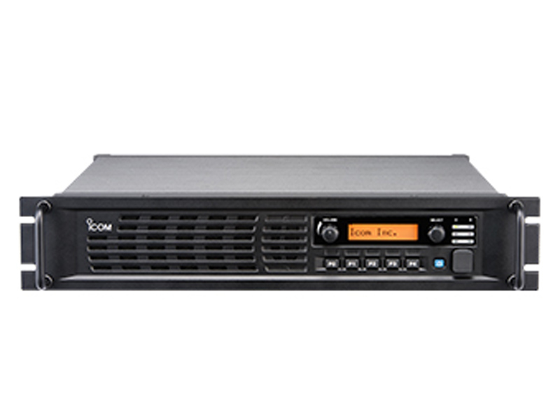
ICOM UHF Digital Repeater
Thank you for choosing this Icom product. This product is designed and built with Icom’s s state of the art technology and craftsmanship. With proper care, this product should provide you with years of trouble-free operation.
FEATURES
- Up to 2 channels of operationYou can install a channel extension module (optional UR-FR5300/UR-FR6300) into a repeater. Two channels can be operated on the same repeater when a channel extension module is installed.
- Built-in 5-Tone, DTMF encoder & decoderMultiple signaling systems are built-in as standard. These systems are fully compatible with Icom F-series radios.
- DTMF remote control capability You can control the repeater from a remote location over the air or over a phone line with DTMF.
- D-Sub 25 pin ACC port equippedYou can use optional equipment through the D-sub 25 pin ACC port on the repeater’s rear panel.
- Online control and Digital Trunking operationOnline control and digital trunking operation are available when the optional UC-FR5300 TRUNKING/ NETWORK CONTROLLER is installed in the repeater.
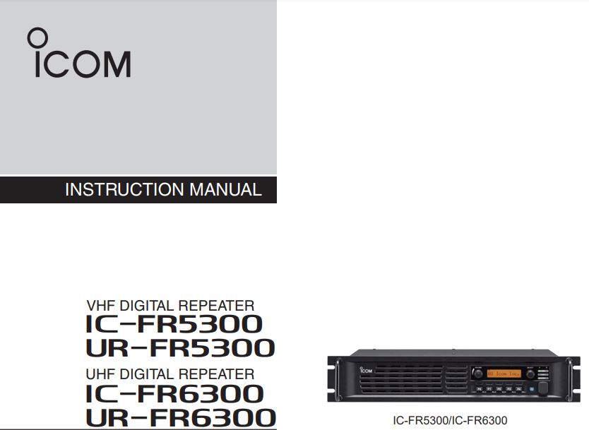
- Other features– Wide frequency coverage<VHF>IC-FR5300/UR-FR5300: 136 to 174 MHz<UHF>IC-FR6300/UR-FR6300: 330 to 400 MHz,400 to 470 MHz,450 to 512 MHz,450 to 520 MHz– PC programmable– 19-inch rack-mount
Icom is not responsible for the destruction or damage to the Icom transceiver if the malfunction is because of:
- Force majeure, including, but not limited to, fires, earthquakes, storms, floods, lightning, other natural disasters, disturbances, riots, war, or radioactive contamination.
- The use of Icom transceivers with any equipment that is not manufactured or approved by Icom.
IMPORTANT
READ THIS INSTRUCTION MANUAL CAREFULLY before attempting to operate the re-peter.SAVE THIS INSTRUCTION MANUAL Thismanual contains important safety and operating instructions for the IC-FR5300/UR-FR5300/IC-FR6300/ UR-FR6300 VHF/UHF DIGITAL REPEATERS.
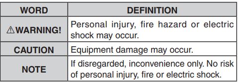
EXPLICIT DEFINITIONS
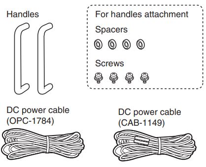
SUPPLIED ACCESSORIES
The following accessories are supplied.
Icom, Icom Inc., and the Icom logo are registered trademarks of Icom Incorporated (Japan) in Japan, the United States, the United Kingdom, Germany, France, Spain, Russia, Australia, New Zealand, and/or other countries. All other products or brands are registered trademarks or trademarks of their respective holders.
PRECAUTIONS
![]() WARNING HIGH VOLTAGE! NEVER touch an antenna or internal antenna connector while transmitting. This could cause an electrical shock or RF burn.
WARNING HIGH VOLTAGE! NEVER touch an antenna or internal antenna connector while transmitting. This could cause an electrical shock or RF burn.
![]() WARNING HIGH VOLTAGE! NEVER install the antenna at any place that person easily touches the antenna while transmitting. This could cause an electrical shock or RF burn.
WARNING HIGH VOLTAGE! NEVER install the antenna at any place that person easily touches the antenna while transmitting. This could cause an electrical shock or RF burn.
![]() WARNING! NEVER apply AC power to the DC power receptacle on the repeater rear panel. This could cause a fire or damage the repeater.
WARNING! NEVER apply AC power to the DC power receptacle on the repeater rear panel. This could cause a fire or damage the repeater.
![]() WARNING! NEVER apply more than 16 V DC to the DC power receptacle on the repeater rear panel. This could cause a fire or damage the repeater.
WARNING! NEVER apply more than 16 V DC to the DC power receptacle on the repeater rear panel. This could cause a fire or damage the repeater.
![]() WARNING! NEVER reverse the DC power cable polarity. This could cause a fire or damage the repeater.
WARNING! NEVER reverse the DC power cable polarity. This could cause a fire or damage the repeater.
![]() WARNING! NEVER let metal, wire or other objects contact the inside of the repeater, or make incorrect contact with connectors on the rear panel. This could cause an electric shock or damage the repeater.
WARNING! NEVER let metal, wire or other objects contact the inside of the repeater, or make incorrect contact with connectors on the rear panel. This could cause an electric shock or damage the repeater.
CAUTION: DO NOT place or leave the repeater in areas with temperatures below 30°C (22°F) or above+60°C (+140°F). Be aware that temperatures can exceed 80°C (+176°F), resulting in permanent damage to the repeater if left there for extended periods.
CAUTION: DO NOT place or leave the repeater in excessively dusty environments. This could damage the repeater.
CAUTION: DO NOT put anything on top of the repeater. This will obstruct heat dissipation.
CAUTION: DO NOT set the repeater’s RF output power to more than your external linear amplifier’s maximum input level, if you use one. Otherwise, a high input could damage the linear amplifier.
CAUTION: DO NOT use non-Icom microphones. Other manufacturer’s microphones may have different pin assignments and could damage the connector and/or the repeater.
BE CAREFUL! The heatsink will become hot when continuously operating the repeater for long periods of time.
NEVER expose the repeater to rain, snow, or any liquids.
NEVER leave the repeater in an insecure place to avoid use by unauthorized persons.
SAFETY TRAINING INFORMATION
 Your Icom radio generates RF electromagnetic energy during transmit mode. This radio is designed for and classified as “Occupational Use Only,” meaning it must be used only during the course of employment by individuals aware of the hazards, and the ways to minimize such hazards. This radio is NOT intended for use by the “General Population” in an uncontrolled environment.
· For compliance with FCC and IC RF Exposure Requirements, the transmitter antenna installation shall comply with the following three conditions:1. The transmitter antenna gain shall not exceed 0 dBi.2. IC-FR5300/UR-FR5300: Transmit only when people are at least the recommended minimum distance of 60 centimeters away from the properly installed antenna. This separation distance will ensure that there is sufficient distance from a properly installed externally-mounted antenna to satisfy the RF exposure requirements in the applicable RF exposure compliance standards.2. IC-FR6300/UR-FR6300: Transmit only when people are at least the recommended minimum distance of 50 centimeters away from the properly installed antenna. This separation distance will ensure that there is sufficient distance from a properly installed externally-mounted antenna to satisfy the RF exposure requirements in the applicable RF exposure compliance standards.
![]() To ensure that your exposure to RF electromagnetic energy is within the FCC and IC allowable limits for occupational use, always adhere to the following guidelines:
To ensure that your exposure to RF electromagnetic energy is within the FCC and IC allowable limits for occupational use, always adhere to the following guidelines:
· DO NOT operate the radio without a proper antenna attached, as this may damage the radio and may also cause you to exceed FCC and IC RF exposure limits. A proper antenna is an antenna supplied with this radio by the manufacturer or an antenna specifically authorized by the manufacturer for use with this radio.· DO NOT transmit for more than 50% of total radio use time (“50% duty cycle”). Transmitting more than 50% of the time can cause FCC and IC RF exposure compliance requirements to be exceeded. The radio is transmitting when the “TX indicator” lights red. You can cause the radio to transmit by pressing the “PTT” switch.
Electromagnetic Interference/CompatibilityDuring transmissions, your Icom radio generates RF energy that can possibly cause interference with other devices or systems. To avoid such interference, turn off the radio in areas where signs are posted to do so. DO NOT operate the transmitter in areas that are sensitive to electromagnetic radiation such as hospitals, aircraft, and blasting sites.
1 PANEL DESCRIPTION
Front panel
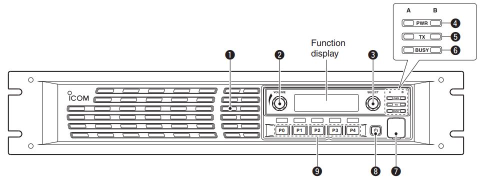
(1) INTERNAL SPEAKER Outputs the received audio.
(2) VOLUME CONTROL [VOLUME] (p. 7) Adjusts the audio output level.
(3) SELECTOR DIAL [SELECT] Rotate to adjust the squelch threshold level, select the operating channel. (Depending on the presetting.)
(4) POWER INDICATOR [POWER] Lights green at `A’ module’s indicator while the repeater power is turned ON.
When a channel extension module is installed:— Lights green at the selected module indicator (`A’ or `B’) while the repeater power is turned ON.— Lights orange at the un-selected module indicator (`A’ or `B’) while the repeater power is turned ON.
(5) TRANSMIT INDICATOR [TX] Lights red while transmitting.
(6) BUSY INDICATOR [BUSY] Lights green while receiving a signal or when the noise squelch is open.
About [PWR], [TX], and [BUSY] indicators:`A’ and `B’ module indicators are usable for these indications. `A’ module’s indicator corresponds to the original module, and `B’ module’s indicator corresponds to an extended module.
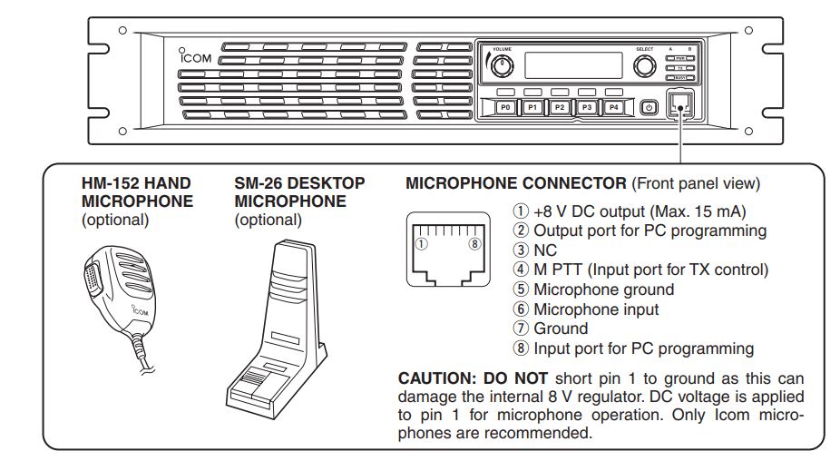
(7) MICROPHONE CONNECTOR [MIC] This 8-pin modular jack accepts an optional micro-phone.
KEEP the [MIC] connector cover attached to the repeater when an optional microphone is not used.
 (1)+8 V DC output (Max. 15 mA)(2) Output port for PC programming(3) NC(4) M PTT (Input port for TX control)(5) Microphone ground(6) Microphone input(7) Ground(8) Input port for PC programming
(8) POWER SWITCH [POWER]—Push to turn ON the repeater power.—Hold down for 3 seconds to turn OFF the repeater power.When a channel extension module is installed:—While the repeater power is turned ON, push to select the desired moduleto operate the repeater as the base station.· The power indicator of the selected module unit lights green.
(9) DEALER-PROGRAMMABLE KEYSDesired functions can be independently preset by your dealer. Ask your dealer for details.· Because these keys are programmable, the functionsare unique to each unit.
Function display
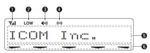
(1) SIGNAL STRENGTH INDICATOR Indicates the relative signal strength level.
(2) LOW POWER INDICATORGNSS (Global Navigation Satellite System) positioning is established.
(3) AUDIBLE INDICATOR Displays when the channel is in the `audible’ (un-mute) mode.
(4) GNSS INDICATORDisplays when the UC-FR5300 is installed, and the Displays when the low output power is selected. This indicator can be deactivated using programming software.
(5) ALPHANUMERIC DISPLAYShows a variety of text or code information.
(6) KEY ICONDisplays when the key assigned as the [Lock] or [Tx Disable] key and it is active.
Rear panel

(1) DC POWER CONNECTOR (For cooling fans)Connects to the supplied CAB-1149 DC power cable from this connector to an external 13.6 V DC power source to activate the cooling fans. See page 5 for the connection details.
(2) EXTERNAL SPEAKER CONNECTOR [SP]Connects to the optional SP-35.
(3) RECEIVE ANTENNA CONNECTOR [RX]Connects to a receive antenna (impedance: 50Ω).
(4) ACCESSORY CONNECTOR [ACC]Connects to the accessory connector.· See p. 3 for accessory connector information.
(5) DC POWER RECEPTACLEConnects to the supplied OPC-1784 DC power cable from an external 13.6 V DC power source. See page 5 for the connection details.
(6) TRANSMIT ANTENNA CONNECTOR [TX]Connects to a transmit antenna (impedance: 50 Ω).
Accessory connector
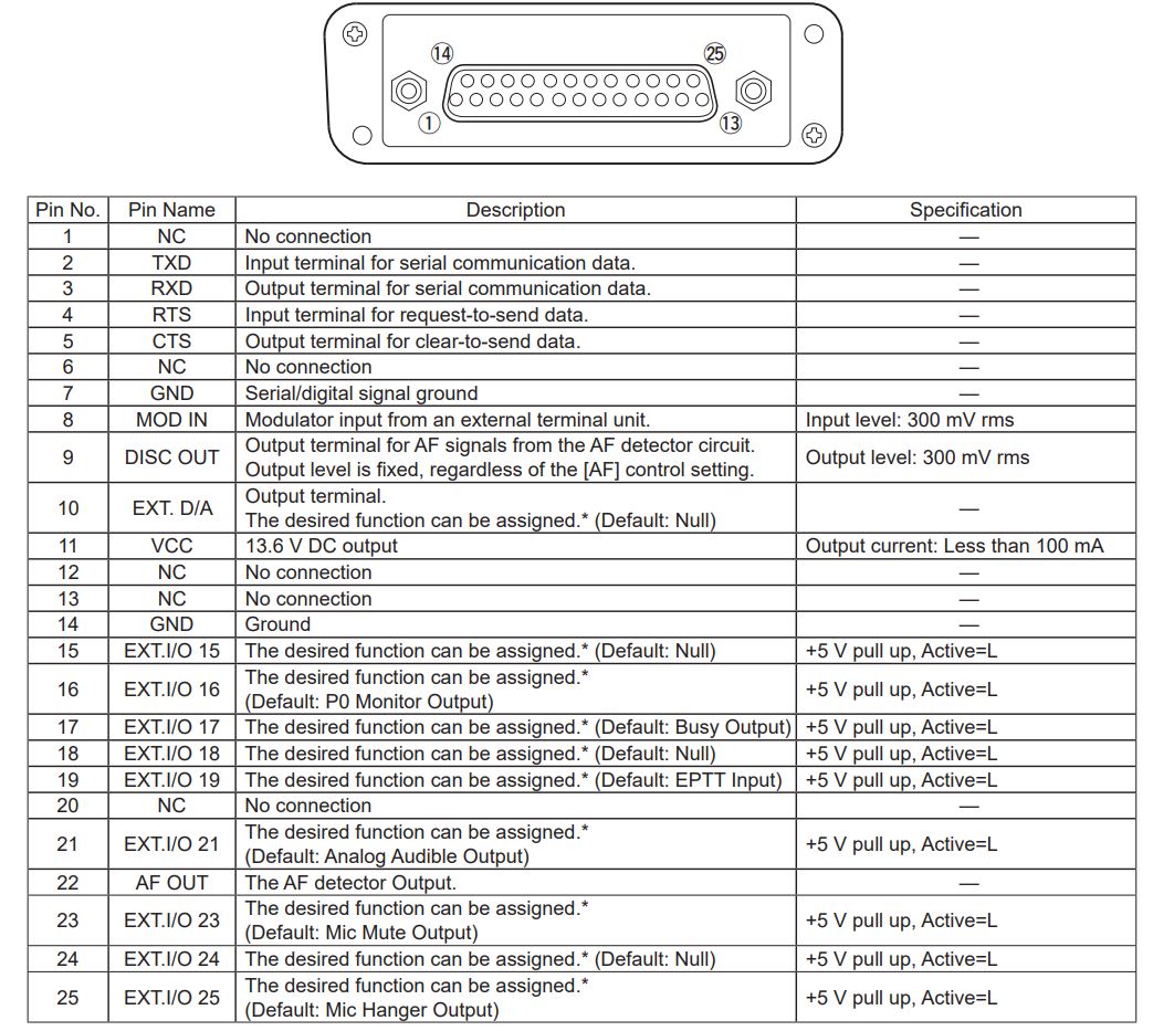
* The desired function can be assigned using the optional CS-FR5300 CLONING SOFTWARE. Ask your dealer for details. 3
2 INSTALLATION AND CONNECTIONS
Unpacking
After unpacking, immediately report any damage to the delivering carrier or dealer. Keep the shipping cartons.For a description and a diagram of accessory equipment included with the repeater, see `SUPPLIED ACCESSORIES’ on page I of this manual.
Antenna connection
For radio communications, the antenna is a critical component, along with output power and sensitivity. Select antenna(s), such as a well-matched 50 ø antenna, and feed line. 1.5:1 or better of Voltage Standing Wave Ratio (VSWR) is recommended for the desired band. Of course, the transmission line should be a coaxial cable.
Selecting a location
Select a location for the repeater that allows adequate air circulation, free from extreme heat, cold, or vibrations, and away from TV sets, TV antenna elements, radios, and other electromagnetic sources.
CAUTION: DO NOT install the repeater without a lightning arrestor to help protect the repeater from lightning.
NOTE: There are many publications that describe proper antennas and their installation. Check with your local dealer for more information and recommendations.
Front panel connection
Rear panel connection

*This connection may not be required, depending on the repeater version. The repeater rear panel may be different, depending on the repeater version.
Power supply connection
Make sure the repeater’s power is turned OFF when connecting a DC power cable.![]() WARNING! NEVER apply more than 16 V DC to the DC power receptacle on the repeater rear panel. This could cause a fire or damage the repeater.
WARNING! NEVER apply more than 16 V DC to the DC power receptacle on the repeater rear panel. This could cause a fire or damage the repeater.
Mounting the repeater
Using the supplied handles
The supplied handles are used when mounting the repeater into a 19-inch rack. The handles are installed on the repeater’s front panel.
(1) Attach the supplied handles to both sides of the repeater’s front panel with the spacers, then tighten the screws as shown below.

(2) The completed installation should look like the illustration below.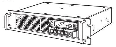
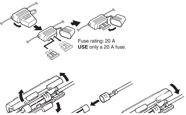
Fuse replacement
If a fuse blows, or the repeater stops functioning, find the source of the problem, repair it and then replace the damaged fuse with a new rated one.
CAUTION: DO NOT replace the fuse with the DC power cable connected to the repeater. Disconnect the cable to prevent electric shock and/or equipment damage.
Line fuse replacement
3 OPERATION
Receiving and transmitting
Repeater operation
Ask your dealer for details of the repeater’s presettings.— When the power is turned ON, the [PWR] indicator lights green. (p. 1)— The [TX] or [BUSY] indicator lights simultaneously while transmitting/receiving a signal.· The [TX] indicator lights red.· The [BUSY] indicator lights green.
NOTE: A power amplifier protector is built into the repeater. The protector is activated when the repeater temperature becomes extremely high due to long periods of transmitting to reduce the transmit output power level. The output power will return to its normal level when the repeater has cooled down.
Base station operation
Receiving(1) Push [POWER] to turn ON the power.(2) Set the audio and squelch levels.— Rotate [SELECT]*1 fully counterclockwise in advance.— Rotate [VOLUME] to adjust the audio output level.— Rotate [SELECT]*1 clockwise until the noise just disappears.(3) Push [CH Up]*2 or [CH Down]*2 to select the desired channel.· When receiving a signal, the [BUSY] indicator lights green, and audio is heard from the speaker.· Further adjustment of [VOLUME] to a comfortable listening level may be necessary at this point.
*1 When the [SQL Level Up/Down] key function is assigned to [SELECT].*2 When the [CH Up]/[CH Down] key functions are assigned.
Transmitting(1) Take the microphone off-hook.(2) Wait for the channel to become clear.(3) Hold down [PTT] to transmit, then speak into the microphone at your normal voice level.(4) Release [PTT] to receive.
IMPORTANT: To maximize the audio quality of the transmitted signal:1. Pause briefly after pushing [PTT].2. Hold the microphone 5 to 10 cm (2 to 4 inch)from your mouth, then speak at your normal voice level.
4 MAINTENANCE
Troubleshooting
The following chart is designed to help you correct problems that are not equipment malfunctions.
If you are unable to locate the cause of a problem or solve it through the use of this chart, contact your nearest Icom Dealer or Service Center.

5 OPTIONS
· SP-35 EXTERNAL SPEAKERCompact and easy to install.Input impedance: 4 ΩRated input: 5 WMaximum input: 7 W· HM-152 HAND MICROPHONE· SM-26 DESKTOP MICROPHONE· UR-FR5300/UR-FR6300 CHANNEL EXTENSION MODULES· UC-FR5300 TRUNKING/NETWORK CONTROLLER
Some options may not be available in some countries. Please ask your dealer for details.
6 INFORMATION
Voice coding technology
The AMBE+2TM voice coding Technology embodied in this product is protected by intellectual property rights including patent rights, copyrights, and trade secrets of Digital Voice Systems, Inc. This voice coding Technology is licensed solely for use within this Communications Equipment. The user of this Technology is explicitly prohibited from attempting to extract, remove, decompile, reverse engineer, or disassemble the Object Code, or in any other way convert the Object Code into a human-readable form. U.S. Patent Nos. #8,595,002, #8,359,197, #8,315,860, #8,200,497, #7,970,606, and #6,912,495 B2.
FCC information
This equipment has been tested and found to comply with the limits for a Class B digital device, pursuant to part 15 of the FCC Rules. These limits are designed to provide reasonable protection against harmful interference in a residential installation. This equipment generates, uses, and can radiate radio frequency energy and, if not installed and used in accordance with the instructions, may cause harmful interference to radio communications. However, there is no guarantee that interference will not occur in a particular installation. If this equipment does cause harmful interference to radio or television reception, which can be determined by turning the equipment off and on, the user is encouraged to try to correct the interference by one or more of the following measures:
- Reorient or relocate the receiving antenna.
- Increase the separation between the equipment and receiver.
- Connect the equipment into an outlet on a circuit different from that to which the receiver is connected.
- Consult the dealer or an experienced radio/TV technician for help.
CAUTION: Changes or modifications to this repeater, not expressly approved by Icom Inc., could void your authority to operate this repeater under FCC regulations.
Count on Us!
A?????-1EXPrinted in Japan© 2020 Icom Inc.
1-1-32 Kamiminami, Hirano-ku, Osaka 547-0003, Japan
[xyz-ips snippet=”download-snippet”]