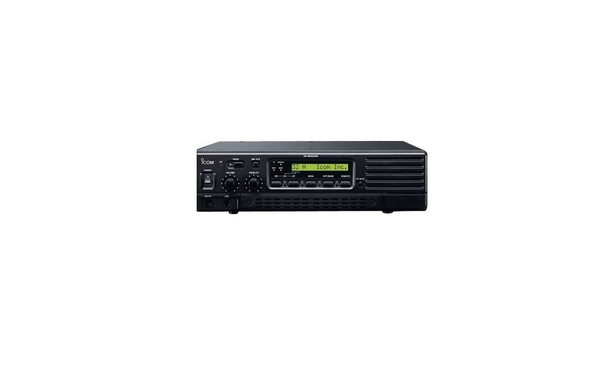
Icom VHF/UHF FM Repeater Instruction Manual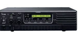
IMPORTANT
READ THIS INSTRUCTION MANUAL CAREFULLY before attempting to operate the repeater.
SAVE THIS INSTRUCTION MANUAL– This manual contains important safety and operating instructions for the CY FR series.
PRECAUTION
![]() WARNING HIGH VOLTAGE! NEVERattach an antenna or internal antenna connector during transmission. This may result in an electrical shock or burn.
WARNING HIGH VOLTAGE! NEVERattach an antenna or internal antenna connector during transmission. This may result in an electrical shock or burn.
![]() WARNING HIGH VOLTAGE! NEVERinstall the antenna at any place that person touch the antenna easily during transmission. This may result in an electrical shock or burn.
WARNING HIGH VOLTAGE! NEVERinstall the antenna at any place that person touch the antenna easily during transmission. This may result in an electrical shock or burn.
![]() NEVER apply AC to the [BATTERY] terminals on the repeater rear panel. This could cause a fire or damage the repeater.
NEVER apply AC to the [BATTERY] terminals on the repeater rear panel. This could cause a fire or damage the repeater.
![]() NEVER apply more than 16 V DC, such as a 24 V battery, to the [BATTERY] terminals on the repeater rear panel. This could cause a fire or damage the repeater.
NEVER apply more than 16 V DC, such as a 24 V battery, to the [BATTERY] terminals on the repeater rear panel. This could cause a fire or damage the repeater.
![]() NEVER let metal, wire or other objects touch any internal part or connectors on the rear panel of the repeater. This may result in an electric shock.
NEVER let metal, wire or other objects touch any internal part or connectors on the rear panel of the repeater. This may result in an electric shock.
![]() NEVER expose the repeater to rain, snow or any liquids.
NEVER expose the repeater to rain, snow or any liquids.
AVOID using or placing the repeater in areas with temperatures below –30°C (–22°F) or above +60°C (+140°F). Be aware that temperatures on a vehicle’s dashboard can exceed 80°C (+176°F), resulting in permanent damage to the repeater if left there for extended periods.
AVOID placing the repeater in excessively dusty environments or in direct sunlight.
EXPLICIT DEFINITIONS
|
WORD |
DEFINITION |
|
WARNING |
Personal injury, fire hazard or electric shock may occur. |
|
CAUTION |
Equipment damage may occur. |
|
NOTE |
If disregarded, inconvenience only. No risk of personal injury, fire or electric shock. |
AVOID putting anything on top of the repeater.This will obstruct airflow.Place the repeater in a secure place to avoid inadvertent use by children.
BE CAREFUL! The heatsink will become hot when operating the repeater continuously for long periods.
BE CAREFUL! If a linear amplifier is connected, set the repeater’s RF output power to less than the linear amplifier’s maximum input level, otherwise, the linear amplifier will be damaged.
Use Icom microphones only. Other manufacturer’s microphones have different pin assignments, and connection to the CY FR series may damage the repeater.
For U.S.A. onlyCAUTION: This repeater is intended for use as a fixed repeater with the antenna located outdoors on the rooftop or on antenna tower.
The Icom America Systems logo is a trademark of Icom, Inc.
FORWARD
Thank you for purchasing this Icom America Systems CY FR VHF/UHF repeater. With proper care, this product should provide you years of trouble-free operation.
- FEATURES
- Automatic battery backup and charging systemA built-in backup system supports automatic switching to an external battery (13.6 V DC) if the AC power supply fails.
- Other features
- PC programmable19 inch rack mount or desktop
SUPPLIED ACCESSORIES
The following accessory is supplied with CY FR series
[AC120V version] ➀ AC power cable (OPC-510).
PANEL DESCRIPTION
- Front Panel

- MICROPHONE CONNECTOR [MIC]Use Icom microphones only. Other manufacturer’s microphones have different pin assignments, and connection to the CY FR series may damage the repeater.
- +8 V DC output (Max. 15 mA)
- Output port for PC programming
- AFO
- M PTT (Input port for TX control)
- Microphone ground
- Microphone input
- Ground
- Input port for PC programming
- Rear Panel

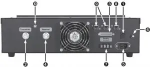
- LIGHTED POWER SWITCH [POWER]Toggles to turn the repeater AC power ON or OFF. Located on the back panel of the repeater.NOTE: Does not effect DC power input.
- TRANSMIT ANTENNA CONNECTOR [TX/ TX•RX]
- Connects a transmit antenna (impedance: 50 Ω) and outputs transmit signals.
- When an optional internal duplexer is installed, this connects the Transmit and Receive Radios to an antenna.
- N Female Connector.
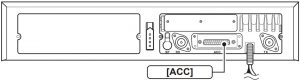
- ACCESSORY CONNECTOR [ACC]Connects to the remote controller.
- RECEIVE ANTENNA CONNECTOR [RX]Connects a receive antenna (impedance: 50Ω) and inputs receiving signals.➥When an optional internal duplexer isinstalled, do not use this connector.➥N Female Connector.
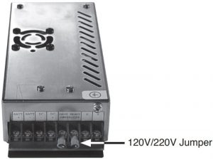
- AC POWER SOCKET [AC]Connects the supplied AC power cable to a 120V or 220V AC outlet.120V or 220V internal jumper selectable.
- GROUND TERMINAL [GND]Ground the repeater through this terminal to prevent electric shocks, TVI, BCI and other problems.
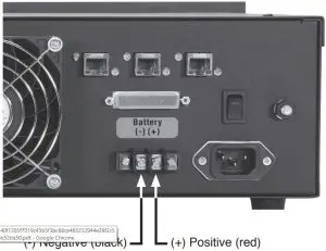
- DC POWER INPUT TERMINALS [BATTERY]Connects the 12 V storage battery for the repeater backup when the AC power is interrupted. These terminals are also used for DC power operation. Battery is automatically recharged when AC power is restored.CAUTION: NEVER short the (+) line of the DC power cable to repeater’s chassis, when connecting DC power cable to the [BATTERY] terminals. Otherwise, there is danger of electric shock and/or equipment damage.
- LAN CONNECTORfor ethernet connection when optional UC-FR5300 controller installed.
- BUS CONNECTORSfor data communication among optional UC-FR5300 controllers.
- GPS CONNECTOR connects to the optional GPS antenna.
Accessory Connector
|
ACC |
|||
|
Pin No. |
Pin Name | Description |
Specification |
|
1 |
NC | No connection | — |
| 2 | TXD | Input terminal for serial communication data. |
— |
|
3 |
RXD | Output terminal for serial communication data. | — |
| 4 | RTS | Input terminal for request-to-send data. |
— |
|
5 |
CTS | Output terminal for clear-to-send data. | — |
| 6 | NC | No connection |
— |
|
7 |
GND | Serial/digital signal ground | — |
| 8 | MOD IN | Modulator input from an external terminal unit. |
Input level: 85 mV rms |
|
9 |
DISC OUT |
Output terminal for AF signals from the AF detector circuit. Output level is fixed, regardless of the [AF] control setting. |
Output level: 300 mV rms |
| 10 | EXT. D/A | Output terminal.
The desired function can be assigned.* (Default: Null) |
— |
|
11 |
VCC | Power supply voltage output | Output current: Less than 100 mA |
| 12 | N/C | No connection |
— |
|
13 |
N/C | No connection | — |
| 14 | GND | Ground |
— |
|
15 |
EXT.I/O 15 |
A desired function can be assigned.*
(Default: Null) |
— |
|
16 |
EXT.I/O 16 |
A desired function can be assigned.*
(Default: P0 Monitor Output) |
— |
|
17 |
EXT.I/O 17 |
A desired function can be assigned.*
(Default: Busy Output) |
— |
| 18 | EXT.I/O 18 | The desired function can be assigned.*
(Default: Null) |
— |
|
19 |
EXT.I/O 19 |
A desired function can be assigned.*
(Default: Null) |
— |
| 20 | N/C | No connection |
— |
|
21 |
EXT.I/O 21 | A desired function can be assigned.* (Default: Analog Audible Output) | — |
| 22 | AF OUT | The AF detector Output. |
— |
|
23 |
EXT.I/O 23 | A desired function can be assigned.* (Default: Mic Mute Output) | — |
| 24 | EXT.I/O 24 | The desired function can be assigned.*
(Default: Null) |
— |
|
25 |
EXT.I/O 25 |
A desired function can be assigned.*
(Default: Null) |
— |
INSTALLATION AND CONNECTIONS
- UnpackingAfter unpacking, immediately report any damage to the delivering carrier or dealer. Keep the shipping cartons.For a description and a diagram of accessory equipment included with the CY FR series, see ‘Supplied accessories’ of this manual.
- Selecting a locationSelect a location for the repeater that allows adequate air circulation, free from extreme heat, cold, or vibrations, and away from TV sets, TV antenna elements, radios and other electromagnetic sources.
- Antenna connectionFor radio communications, the antenna is of critical importance, along with output power and sensitivity. Select antenna(s), such as a wellmatched 50 Ω antenna, and feedline. 1.5:1 or better of Voltage Standing Wave Ratio (VSWR) is recommended for desired band. Of course, the transmission line should be a coaxial cable.CAUTION: Protect repeater from lightning by using a lightning arrestor.NOTE: There are many publications covering proper antennas and their installation. Check with your local dealer for more information and recommendations.
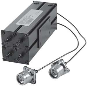
- DuplexerA duplexer is separately required when only one antenna is used for both transmitting and receiving. Select a duplexer according to the transmitting and receiving frequencies. Ask your Dealer for details.
- GroundingTo prevent electrical shock, television interference (TVI), broadcast interference (BCI) and other problems, ground the transceiver through the [GND] terminal on the rear panel.For best results, connect a 2-gauge wire to an 8-foot long earth-sunk copper rod. Make the distance between the [GND] terminal and ground as short as possible.
- WARNING: NEVER connect the [GND] terminal to a gas or electric pipe, since the connection could cause an explosion or electric shock.
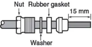
TYPE-N CONNECTOR INSTALLATION EXAMPLE
- Slide the nut, flat washer, rubber gasket and clamp over the coaxial cable, then cut the end of the cable evenly.
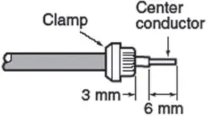
- Strip the cable and fold the braid back over the clamp.
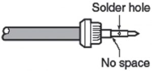
- Soft solder the center conductor. Install the center conductor pin and solder it.
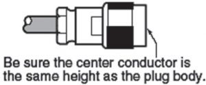
- Carefully slide the plug body into place aligning the center conductor pin on the cable. Tighten the nut onto the plug body.
Required Connections

DC POWER INPUT TERMINAL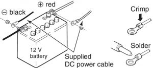 Make sure the back up battery is correctly connected. Use a cable with following current capacity. Solder or clamp the cable plug when connecting the power cable to the backup battery to prevent voltage drops.Power cable current capacity: 25 A or more
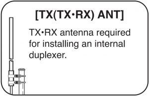
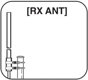

NOTE: Must have minimum 20’ vertical separation when using separate antennas.
- PowerMake sure the AC [POWER] switch is turned OFF when connecting an AC power cable or a backup battery (emergency power supply). The CY FR series can operate with either an AC or DC input. If AC power is interrupted and there is an external DC source (emergency power supply), the Repeater will continue to operate until the DC source is exhausted.The CY FR series can operate with either an AC or DC input. If AC power is interrupted and there is an external DC source (emergency power supply), the Repeater will continue to operate until the DC source is exhausted.NOTE: IF turning the Repeater OFF using the rear panel switch, wait a few seconds before turning it back ON. Otherwise, Logic circuits may not sense the transition. The AC Power switch does not effect the DC supply. If Repeater is operating on DC, you must use the power switch(s) on the Radio.
- In AC operation
- Use the supplied AC power cable for connection to a domestic AC outlet.
- Extension cords should not be used unless absolutely necessary. Using improper extension cords could result in fire risk.
- An International AC power cable is available. The internal AC power supply is jumper selectable between 120Vac and 220Vac.
- Remove jumper for 220V operation.
- Install jumper for 120V operation.WARNING: DANGER OF ELECTRIC SHOCK. Disconnect AC power before changing voltage select jumper.
- In DC operationCAUTION: Voltages greater than 16 VDC will damage the repeater. Check the source voltage before connecting the power cable.• DO NOT place the backup battery on or near the repeater. Lead-acid batteries should be placed at least 5 m (16.4 ft.) away from the repeater. Use a heavy duty cable to make the connection and be sure both the positive (red) and negative (black) terminals are correctly connected.• When connecting to the battery, connect the DC power cable to the repeater first, then the positive (red) terminal and negative (black) terminal to the battery. This is to prevent an electric shock or circuit damage.
OPTIONAL UNIT INSTALLATION
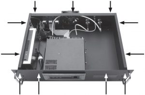
- Opening the repeater’s caseFollow the case and cover opening procedures shown here when an optional unit is installed or adjustments are required to the internal units, etc.
- Remove 3 screws from the top of the repeater r, 4 screws from the sides and 4 screws from the top of the front Panel, then lift up the top cover.
CAUTION: Disconnect the AC power cable and/or DC power cable from the repeater. Otherwise, there is danger of electric shock and/or equipment damage.
- Repeater Case
- OPTIONAL DUPLEXER
- OPTIONAL PRESELECTOR

OPERATION
- Turning power ON
- On rear panel, toggle AC Power Switch up to turn AC power ON.
- Receiving and transmitting
- ReceivingWhen receiving a signal, RX indicator turns ON. No audio is output from the repeater. A subscriber unit will be required to hear the audio.
- Transmitting for Local Control
- Take the microphone off hook.
- Wait for the channel to become clear.
- Push and hold [PTT] to transmit, then speak into the microphone at your normal voice level.
- Release [PTT] to receive.
IMPORTANT:To maximize the readability of the transmitted signal:
- Pause briefly after pushing [PTT].
- Hold the microphone 1 to 2 inch (2.5 to 5 cm) from your mouth, then speak into the microphone at a normal voice level.
MAINTENANCE
Fuse replacementIf a fuse blows or the repeater stops functioning, try to find the source of the problem, and replace the damaged fuse with a new, rated fuse.
CAUTION: DISCONNECT the DC power cable from the repeater. Otherwise, there is a danger of electric shock and/or equipment damage.
SPECIFICATIONS AND OPTIONS
- Specifications (See UR Service Manual for module specifications)
- UR-FR5300GENERALPower supply requirement (nominal) : 105-130 VAC 50/60 hz 5A Max185-250 VAC 50/60 hz 13.6 VDC (nominal) 16.2 Amp MaxDimensions (Projections not included) : 480 (W) x 133 (H) x 364 (D) mm; 18.90 (W) x 524 (H) x 14.33 (D) in. Weight: 8.6 kg; 18 lb 10
- Optional Duplexer and Preselector specifications not listed.
- All specifications are subject to change without notice. (See UR Service Manual for module specifications)
Options
- HM-152 HAND MICROPHONE
- HM-152T DTMF MICROPHONEHand microphone with a DTMF keypad
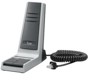
- SM-26 DESKTOP MICROPHONE
- UX-241 GNSS ANTENNA
- Various duplexers and preselectors are available in both VHF and UHF. Please contact Icom America Customer Service to find the currently available options.


[xyz-ips snippet=”download-snippet”]