User Manual
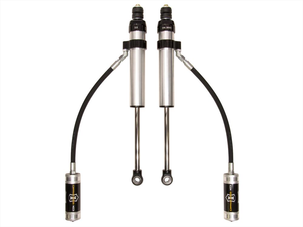
91-07 Land Cruiser 80/100 0-3″ Rear 2.5 VS Remote Reservoir Shock 57802P
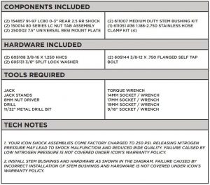
What’s Included
WARNING!
** READ ALL INSTRUCTIONS THOROUGHLY FROM START TO FINISH BEFORE BEGINNING INSTALLATION! IF THESE INSTRUCTIONS ARE NOT PROPERLY FOLLOWED SEVERE FRAME, SUSPENSION AND TIRE DAMAGE MAY RESULT TO THE VEHICLE!
** ICON VEHICLE DYNAMICS RECOMMENDS THAT YOU EXERCISE EXTREME CAUTION WHEN WORKING UNDER A VEHICLE THAT IS SUPPORTED WITH JACK STANDS.
** ICON VEHICLE DYNAMICS RECOMMENDS ALL INSTALLATION TO BE PERFORMED BY A PROFESSIONAL SHOP/SERVICE TECHNICIAN. PRODUCT FAILURE CAUSED BY IMPROPER INSTALLATION WILL NOT BE COVERED UNDER ICON’S WARRANTY POLICY.
INSTALLATION
- Using a properly rated jack, raise the rear of the vehicle and support the frame rails with jack stands. Ensure the jack stands are secure and set properly before lowering the jack. NEVER WORK UNDER AN UNSUPPORTED VEHICLE. Remove the rear wheels.NOTE: This shock fits both 80 Series and 100 Series Land Cruiser models. Follow slight installation differences noted in the instructions.
- With a floor jack under the rear axle, slightly raise the rear axle housing to remove tension, loosen and remove the lower shock bolts. Make sure the axle is well supported. Keep all of the factory hardware, it will be reused.
- Disconnect the top of the shock from its upper mount. (80 SERIES) There is a removable upper stem plate with (2) bolts on either side near the top of the shock. Remove the (2) bolts and remove the shock with the plate attached noting the side and orientation of the plate. (100 SERIES) Reach up over the top mount near the coil bucket to access the upper stem nut. This can be a little hard to reach, when it’s loose you may be able to spin the shock to aid in removal.
- Use a 19mm socket/wrench to install the shock stem bushing kit onto the factory shock mount as follows: 9/16” ID stem washer, stem bushing (locator lip up), factory shock mount, stem bushing (locator lip down), 12mm ID stem washer, 12mm nylock nut. Fasten until bushing assembly is snug and nylock is engaged. (SEE DIAGRAM) below

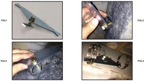
6. There are 2 spacers that go on either side of the bearing on the lower shock mount stud on the axle. The fit of the spacers and the lower shock bearing is a very tight tolerance. It is common for the stud on the axle to get corroded over time. You may need to cleanthe stud prior to installation of the spacers and bearing. Emery cloth or sand paper works best.7. Slide 1 spacer over the stud then the lower shock bearing followed by the other spacer. To assist in lining up the bearing with the stud you will have to jack up the axle very slowly so the parts align. You will also need to rotate the inner part of the bearing to be parallel with the stud, this can be easily done using the female head of a 3/8” extension in the bearing for leverage. Use the OE bolt and captive washer to clamp the lower bearing and spacers. [Torque to 35 ft-lbs]8. Route the reservoir on the inside of the sway bar link and to the outside of the frame.9. Mount the reservoir to the outside of the frame. Custom hardware is provided for 80 series as well as additional universal hardware for 100 series or if alternate reservoir placement is required to clear other aftermarket parts such as rock sliders, etc.10. (80 SERIES) There is a large hole on the side of the frame just above the lower link mount on the frame. Preassemble the 7.5” reservoir mount, 3/8”x 1.25” bolt, washer, and nut plate as shown. Insert the nut plate into the frame square end first until the tab is fully inside the frame. Slide it in the opposite direction until the roll pin is visible and pull out to locate the plate so that the bolt and roll pin locate the plate. Start to tighten the bolt, place the hose clamps in the slots in the bracket before the bracket is fully tightened against the frame. [Torque to 30 ft-lbs] [FIGURE 1 – 4]
11. (80 SERIES) Place the reservoir in the hose clamps. The hose clamps must be mounted outside the edge of the reservoir sticker in the grooves to avoid crushing the reservoir and causing internal damage. Secure the reservoir but do not over tighten hose clamps. [FIGURE 5]

FIG. 5
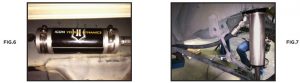
12. (100 SERIES) Fasten the reservoir mounting bracket to the center of the reservoir with the provided hose clamps. The hose clamps must be mounted outside the edge of the reservoir sticker in the grooves to avoid crushing the reservoir and causing internal damage. Do not over tighten hose clamps. [FIGURE 6 & 7]
13. (100 SERIES) Hold the reservoir and mounting bracket against the frame, keep some slack in the hose. The reservoir should be parallel to the bottom of the frame, about 3” from the bottom of the frame. Mark the location of the hole on the frame.
14. (100 SERIES) Move the reservoir and mount away from the frame and drill an 11/32” hole in the spot that you just marked. The passenger side of the vehicle has an exhaust hanger off the body mount, removing the rubber isolator off the hanger will add clearance for drilling but not required. [FIGURE 8]

15. (100 SERIES) Deburr the hole, place the reservoir and mount back against the frame, and install the split washer and self-tapping bolt. The remote reservoir hose clamps may need to be loosened from the bracket to allow the self tapping bolt to slide into position correctly. Secure the reservoir but do not overtighten hose clamps. [FIGURE 9]16. Reinstall wheels and carefully lower the vehicle back to the ground. [Torque lugs to factory spec]
VERIFY ALL FASTENERS ARE PROPERLY TORQUED BEFORE DRIVING VEHICLE.
RETORQUE ALL NUTS, BOLTS AND LUGS AFTER 100 MILES AND PERIODICALLY THEREAFTER.
2.5 VS SERIES SHOCK & COILOVER TECHNICAL INFORMATION
MAINTENANCE
ICON shock absorbers are a high quality rebuildable race style shock absorber designed for optimal performance. With a unit of this caliber on your vehicle, routinemaintenance is required to keep them looking and operating in like new condition. Residual oil and assembly lube may be present at all seal paths from the factory out of thebox and is considered normal. Pooling of oil however is not acceptable at any time and one should contact the ICON dealer where purchased.BELOW ARE GUIDELINES BASED ON HOW YOU USE YOUR VEHICLE BUT YOUR MILEAGE MAY VARY:
STREET USE:
- Send in for factory servicing every 40,000 miles or if a leak develops, ride quality decreases, or they begin to make excessive noise.
- Remove any buildup of road salt, mud, or debris from shocks and coil springs anytime accrued
- Clean with mild soap and water with each oil change or anytime you notice build up.
- Wax the cylinders yearly with automotive wax to prevent corrosion.
- Check nitrogen pressure yearly. (252004 charge needle assembly available at any ICON distributor)
- Check bearings for excessive wear yearly.
- DO NOT apply any type of lube to the upper and lower bearings.
STREET/DIRT:
- Send in for factory servicing every 15,000 miles or if a leak develops, ride quality decreases, or they begin to make excessive noise.
- Clean with mild soap and water with each oil change, offroad trip, or anytime you notice build up.
- Wax the cylinders yearly with automotive wax to prevent corrosion.
- Check nitrogen pressure each dirt outing. (252004 charge needle assembly available at any ICON distributor)
- Check bearings for excessive wear yearly.
- DO NOT apply any type of lube to the upper and lower bearings.
DIRT USE:
- Send in for factory servicing every 1,000 miles.
- Check nitrogen pressure each outing. (252004 charge needle assembly available at any ICON distributor)
- Remove any buildup of mud or debris from shocks and coil springs after every outing.SELF-SERVICE:
- Contact ICON for service kits & tools at (951) 689-4266.
PRODUCT REGISTRATIONPlease visit: http://www.iconvehicledynamics.com/tech-support/registration/ to register your product.
ICON VEHICLE DYNAMICS SHOCK ABSORBER WARRANTYThis shock absorber has a 1 year warranty against any manufacturer’s defects. If a shock fails within the initial year of ownership, the shock must be shipped to ICON Vehicle Dynamics for inspection and service. If a shock is inspected and it has been determined the shock failed due to neglect, damage caused by improper installation or any other reason besides “normal wear and tear”, the owner of said shock is responsible for all service costs. This includes labor, parts, and shipping.
ICON Vehicle Dynamics warrants to the original retail purchaser who owns the vehicle on which the product was originally installed. ICON Vehicle Dynamics does not warrant the product for finish, alterations, modifications and/or installation contrary to ICON Vehicle Dynamics instructions. ICON Vehicle Dynamics products are not designed, nor are they intended to be installed on vehicles used in race applications, for racing purposes or for similar activities. (A “race” is defined as any contest between two or more vehicles, or a contest of one or more vehicles against the clock, whether or not such contest is for a prize). This warranty does not include coverage for police or taxi vehicles, race vehicles, or vehicles used for government or commercial purposes. Also excluded from this warranty are sales outside of the United States of America and Canada.
ICON Vehicle Dynamics’ obligation under this warranty is limited to the repair or replacement, at ICON Vehicle Dynamics’ discretion, of the defective product. Any and all costs of removal, installation or re-installation, freight charges and incidental or consequential damages are expressly excluded from this warranty. Items that are subject to wear are not considered defective when worn and are not covered.
ICON Vehicle Dynamics components must be installed as a complete kit as shown in our current application guide. Any substitutions or exemptions of required components willimmediately void the warranty. Some finish damage may happen to parts during shipping and is not covered under warranty.
This warranty is expressly in lieu of all other warranties expressed or implied. This warranty shall not apply to any product that has been improperly installed, modified or customized subject to accident, negligence, abuse or misuse.
To send a shock in for warranty please visit our website http://www.iconvehicledynamics.com/tech-support/shock-service/
![]()
7929 Lincoln Ave. Riverside, CA 92504 Phone: 951.689.ICON Fax: 951.689.1016www.iconvehicledynamics.com
91-07 Land Cruiser 80/100 0-3″ Rear 2.5 VS Remote Reservoir Shock 57802P User Manual – 91-07 Land Cruiser 80/100 0-3″ Rear 2.5 VS Remote Reservoir Shock 57802P User Manual –
Questions about your Manual? Post in the comments!
[xyz-ips snippet=”download-snippet”]