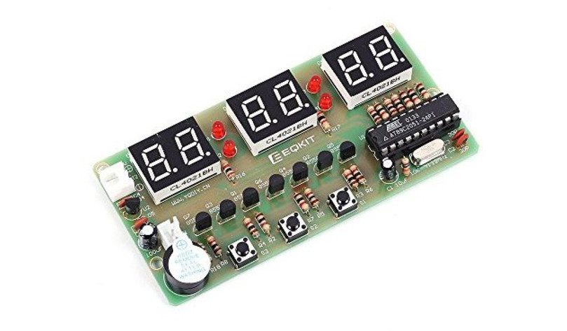
WHDTS 6-Digit Digital Electronic Clock DIY Kits
Introduction
The Digital Electronic Clock Kits are used to install to a 6-Digit Digital Electronic Clock that makesthe full use of the single-chip principle which is featured with the function of an alarm clock, countdown clock,stopwatch and counter.
Features
1>.Alarm clock2>.Stopwatch3>.Countdown4>.Counter5>. Pure work welding6>. Integrated practice area and functional test area7>.LED demonstration exercise results8>.Easy operation
Parameters
1>.Product Name: 6Bit Electronic Clock DIY Kit2>.Work Voltage: DC 3.0V-12.0V3>.Work Temperature: -40℃~85℃4>.Work Humidity: 0%~95%RH5>.Size(Installed): 92*49mm
Components List in The Package
| NO. | Component Name | PCB Marker | Parameter | QTY |
| 1 | SMD 1206 Resistor | R1~R12 | Random | 12 |
| 1 | Metal Film Resistor | R2~R15 | 1K | 14 |
| 2 | Metal Film Resistor | R16~R17 | 2K | 2 |
| 3 | Metal Film Resistor | R18 | 5.1K | 1 |
| 4 | Metal Film Resistor | R1 | 10K | 1 |
| 5 | Ceramic Capacitor | C2,C3 | 30PF | 2 |
| 6 | Ceramic Capacitor | C4,C5 | 0.1uF 104 | 2 |
| 7 | Electrolytic Capacitor | C1 | 10uF/25V | 1 |
| 8 | Electrolytic Capacitor | C6 | 100uF/16V | 1 |
| 9 | Red LED | D1~D4 | 3mm | 4 |
| 10 | 4Bit Red Digital Tube | DS1~DS3 | Common Anode | 3 |
| 11 | Active Buzzer | U3 | 5V | 1 |
| 12 | S8550 Transistor | Q1~Q7 | TO-92 | 7 |
| 13 | AT89C2051 | U1 | DIP-20 | 1 |
| 14 | 78L05 Voltage Regulator | U2 | TO-92 | 1 |
| 15 | Crystal Oscillator | Y1 | 12MHz | 1 |
| 16 | XH2.54mm-2P Socket Right Angle | J2 | 2.54mm | 1 |
| 17 | XH2.54mm-2P Socket | J1 | 2.54mm | 1 |
| 18 | Button | S1~S3 | 6*6*4.3mm | 3 |
| 19 | IC Socket | U1 | DIP-20 | 1 |
| 20 | XH2.54mm-2P Power Wire | J2 | 150mm | 1 |
| 21 | PCB | 92*49mm | 1 |
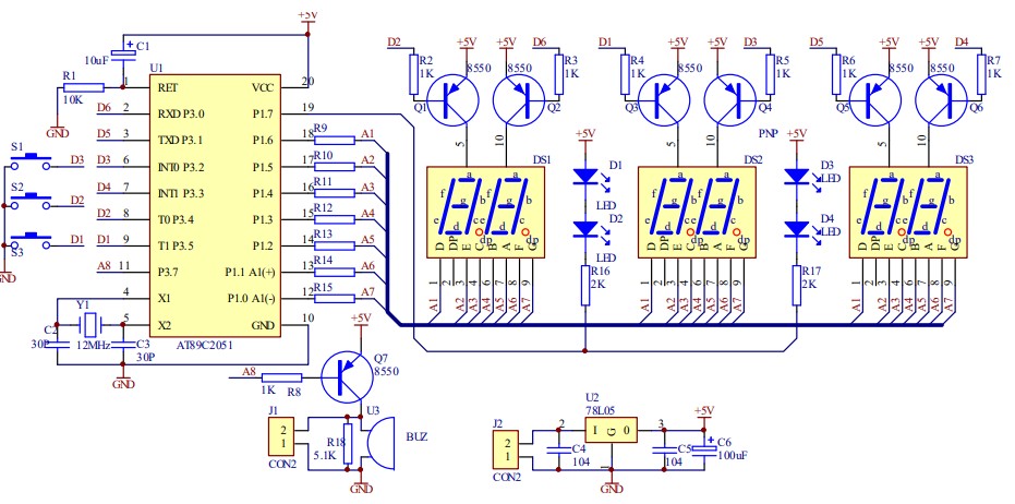
Schematic Diagram
Principle
The circuit is mainly composed of the single-chip circuit, display circuit, keyboard input, signal ringing circuit, and power circuit.
1>.Single-chip circuit: It’s based on AT89C2051 which including the Power-on Reset and clock circuit.
2>.Display Circuit: The main component is 2-bit digital tube in red. The driver uses the PNP transistor and it’s equipped with current-limiting resistance at every port. It’s with scanning-driven way and uses P1.0~P1.6. The colon part uses four pieces of the diode in 3mm red with scanning-driven way. And it uses P1.7.
3>.Keyboard Input: The key S1~S3 are with reused function which reused with the display part of P3.5,P3.4 and P3.2. And here is the operating principle: Output high level at the related PIN to read out the status of keys and debounce via the single-chip system to give the keys with the corresponding value.
4>. Signal Ringing Circuit: It’s composed of a buzzer and PNP transistor. And the operating principle is that the buzzer will send sound in fixed frequency after the PNP transistor turns on. It’s with an independent port-driven way and uses P3.7. J1 is used for connecting the external control equipment which will output the low level when there is no ringing signal or the high level with a ringing signal.
5>.Power Circuit: It’s composed by three-terminal integrated circuits which will supply the whole system with the stable voltage.
Operating Specification:
1>.Specification of Function Keys:S3 is for function choosing key, S2 for function expansion, and S1 for adding the value with one.
2>.Operating:It works well if all the components are welded in the right way. And the operating DC voltage is 7V–12V. Please be noted the polarity when connecting the power. During the operation, below six functions can be chosen to work, if press the S3 continuously in a short time. And the interval is less than 1 second. Or it goes to the clock function if press the S3 for more than 2 seconds.
Clock Function: It displays 10: 10: 00 when it’s on.Time checking Function: The time and colon start flashing after Press the S3 for a short time. PressS2 to add one hour and Press S1 to add 1 minute. But the second time can not be adjustable.Alarming Function: It displays 22: 10: 00 and the colon lights after press S3 twice in a short time. Press S2 to add one hour and Press S1 to add 1 minute. But the second time can not be adjustable. When the value of the hour is over 23: 00 pm, it displays –:—— which is the function for turn off the alarming function.Countdown Function: It displays O and the colon is in dark after press S3 three times in a short time.The hour time is added after pressing S2 and 1 minute is added after pressing S1. It’ll start to countdown when pressing S2 for the sixth time. The time can be adjusted again after pressing S2 for one more time. And the countdown function is off.Stopwatch Function: It displays 00: 00: 00 and the colon lights after press S3 four times in a short time. It starts clocking with the stopwatch after pressing S2. And if press S2 one more time, the clocking will end. And the stopwatch goes to reset status after pressing S1 at this time.Counter Function: It displays 00: 00: 00 and the colon is in dark after press S3 five times in a short time. Press S2 to add the value with one for counter and Press S1 to let the counter in reset status.
Installation Steps
1. Preparation:
- This product comes to you is a DIY kit that needs to be installed, not the finished product!
- DIY Installation is a rather precise operation, which requires patience to finish the project.
- Users need to prepare the welding tool first.
- Users can complete the installation under the instruction of PCB Silk Screen and Components Listed.
- Read the installation manual before starting installation carefully.
- We have been keeping trying to improve the manual. If any words or steps of the instruction confuses you, please feel free to let us know because English is not our first language. We will appreciate your generous help in pointing out our expression problem. Thank you in advance.
2. Operating Notice:More tips about the DIY soldering that will directly affect the performance effect of the finished product as following:
- Pay attention to the positive and negative of certain components. Make sure that all the components were soldered at the right place in the right direction.
- Make sure the bonding pad does not peel off and no pseudo /float soldering. (If it’s not, you can repair the welding or reconnect adjacent components with superfluous metal pins to work things out.)
- The soldering iron mustn’t touch the components for more than one second, or the high temperature of the soldering iron will damage the components.
- Strictly prohibit short circuits.
- If the soldering failed, it can be repaired by sucking out the components and re-soldering bymeans of a solder sucker.
- The user must install the LED according to the specified rules. Otherwise, some LED will not give outlight.
- Install complex components preferentially.
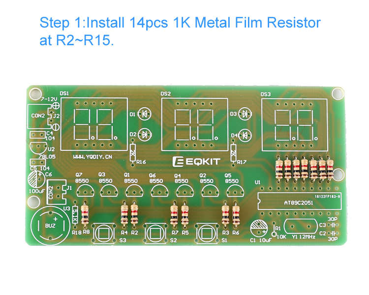
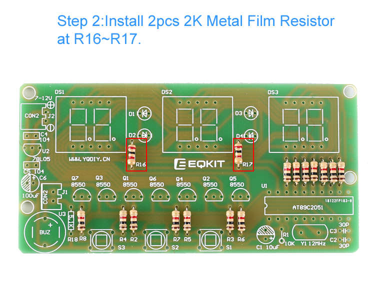
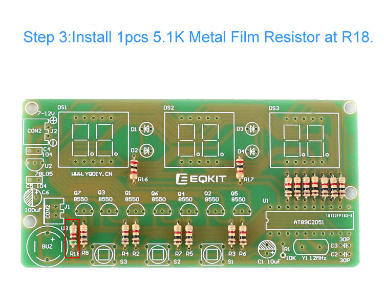
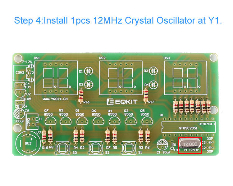
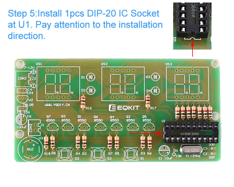
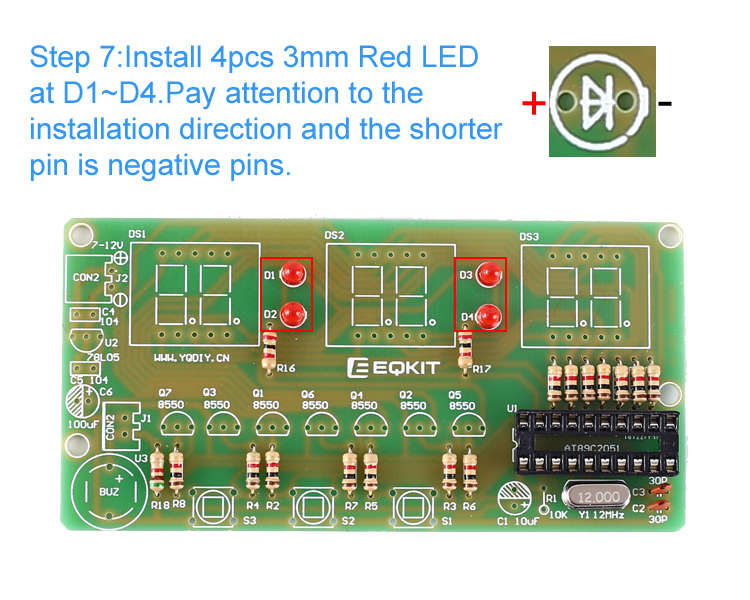
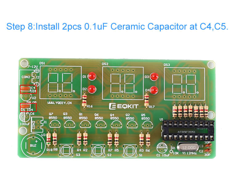
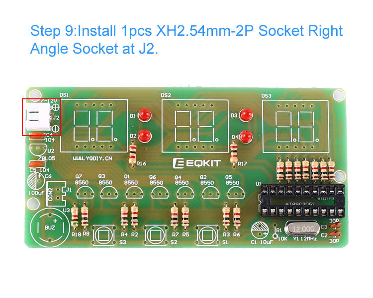
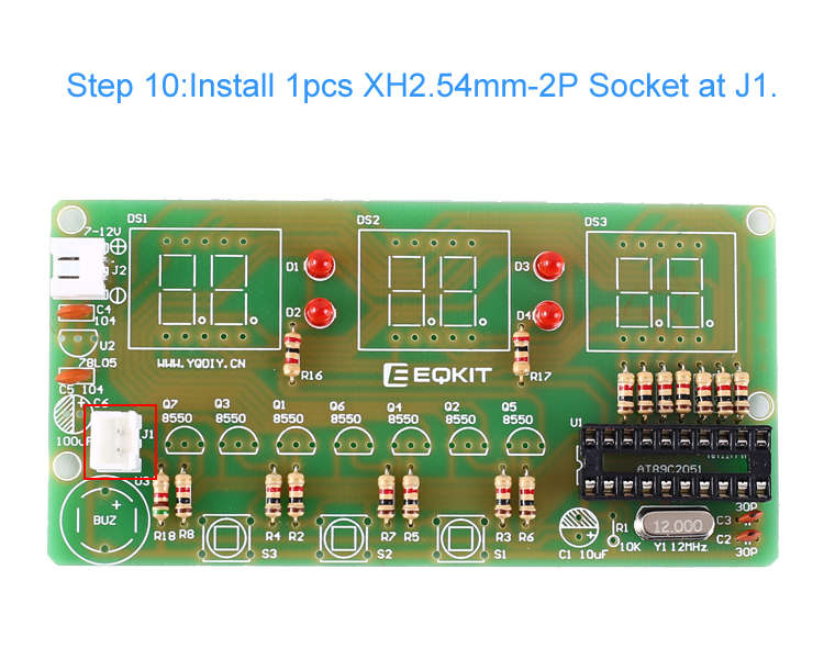
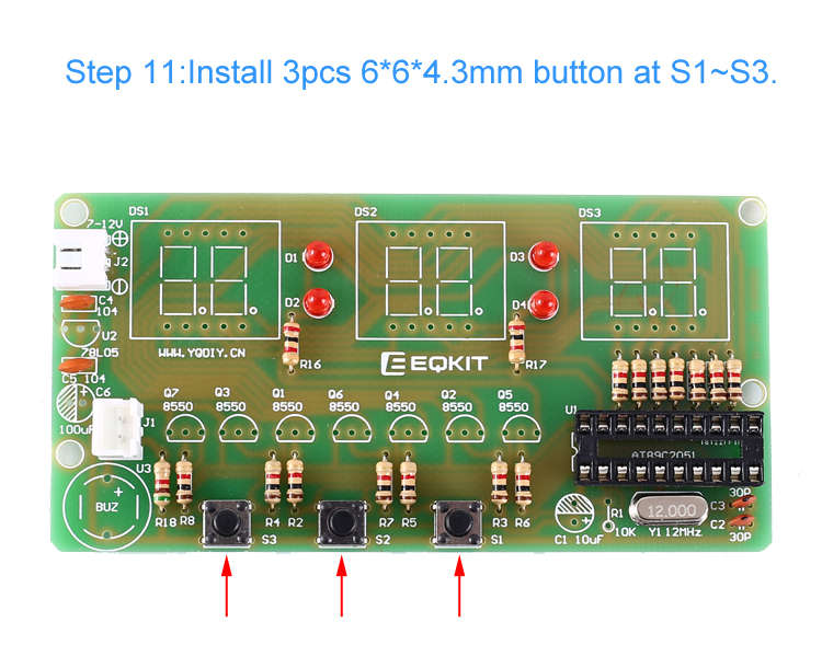
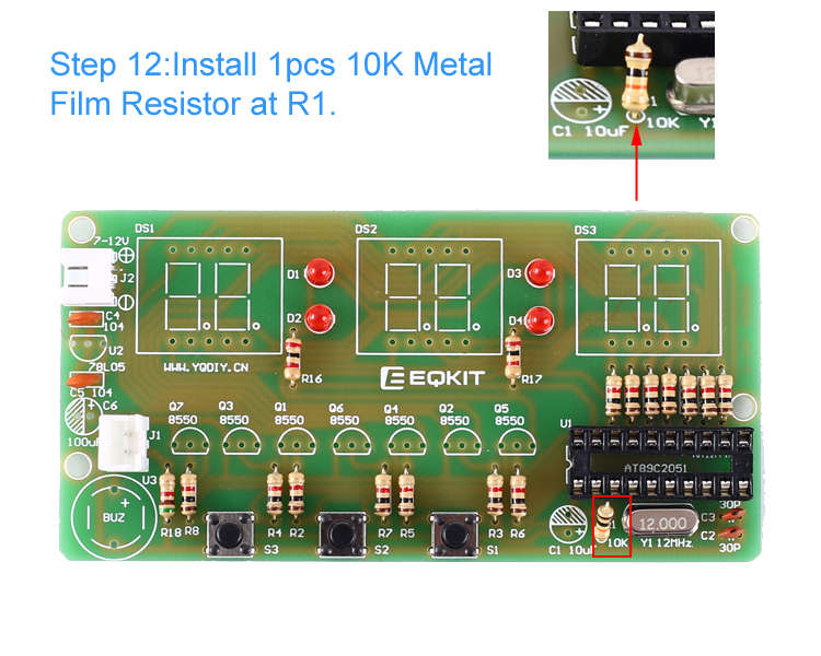
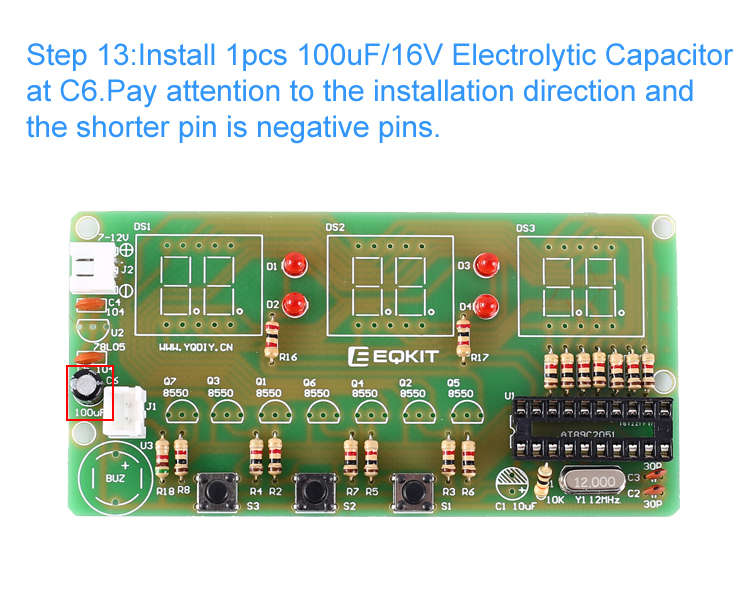
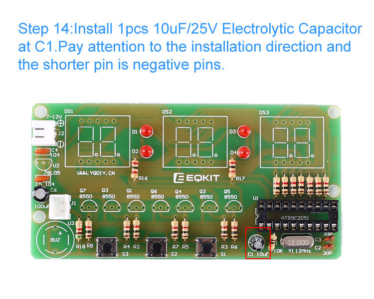
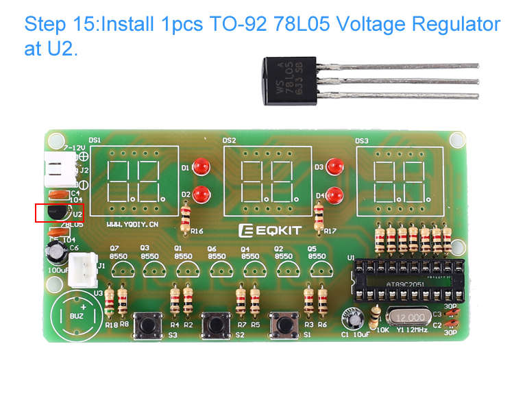
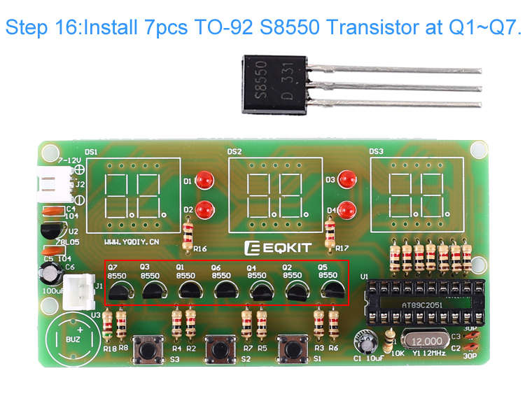
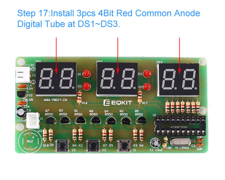
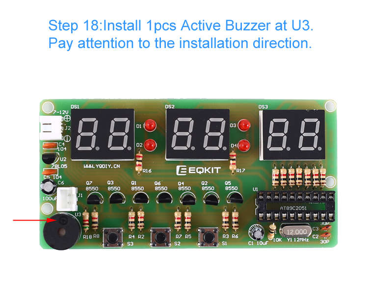
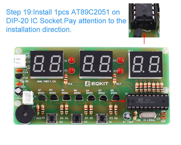
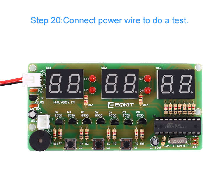
3. Installation Steps & Illustration(Please be patient to install!!!):Step 1: Install 14pcs 1K Metal Film Resistor at R2~R15.Step 2: Install 2pcs 2K Metal Film Resistor at R16~R17.Step 3: Install 1pcs 5.1K Metal Film Resistor at R18.Step 4: Install 1pcs 12MHz Crystal Oscillator at Y1.Step 5: Install 1pcs DIP-20 IC Socket at U1. Pay attention to the installation direction.Step 6: Install 2pcs 30pF Ceramic Capacitor at C2,C3.Step 7: Install 4pcs 3mm Red LED at D1~D4. Pay attention to the installation direction and the shorter pin is negative pins.Step 8: Install 2pcs 0.1uF Ceramic Capacitor at C4,C5.Step 9: Install 1pcs XH2.54mm-2P Socket Right Angle Socket at J2.Step 10: Install 1pcs XH2.54mm-2P Socket at J1.Step 11: Install 3pcs 6*6*4.3mm button at S1~S3.Step 12: Install 1pcs 10K Metal Film Resistor at R1.Step 13: Install 1pcs 100uF/16V Electrolytic Capacitor at C6. Pay attention to the installation direction and the shorter pin is negative pins.Step 14: Install 1pcs 10uF/25V Electrolytic Capacitor at C1. Pay attention to the installation direction and the shorter pin is negative pins.Step 15: Install 1pcs TO-92 78L05 Voltage Regulator at U2.Step 16: Install 7pcs TO-92 S8550 Transistor at Q1~Q7.Step 17: Install 3pcs 4Bit Red Common Anode Digital Tube at DS1~DS3.Step 18: Install 1pcs Active Buzzer at U3. Pay attention to the installation direction.Step 19: Install 1pcs AT89C2051 on DIP-20 IC Socket. Pay attention to the installation direction.Step 20: Connect the power wire to do a test.

Tips about DIY Electronics
This product comes to you is DIY kits that need to be installed, not the finished product! Read the product instruction carefully before installing. And DIY Electronics Operation is a practice activity that requires a certain foundation of basic electronic theoretical knowledge and welding and hands-on ability. We can’t guarantee that all our friends will DIY successfully due to the varying learning phases.
We pledge seriously to you: We could fully satisfy you with our quality products, high-efficiency logistics, and perfect after-sale service! We will do our utmost to assist you to complete the installation. Your satisfaction is our commitment.
If the finished product does not achieve the effect we described or you have any questions or problems with our product or the transaction, unfortunately, don’t rush to give us negative feedback out of anger and impulse, please do not hesitate to contact us directly for further help.
Appendix
- WHAT’S specializes in Electronics Products, such as circuit components, function modules, wireless modules, robotics accessories, DIY kits. WHAT’S devotes a lifetime to providing excellent products with competitive price, fast delivery, and 100% after-sales service for all makers, DIYer, R & D personnel, electronic enthusiasts, students, and teachers. We are aimed at making your electronics projects go with a swing.
- WHAT’S has long been engaged in Electronics Related Products wholesale and retail business. Welcome letter calls to discuss the wholesale and retail
- We have been keeping trying to improve the If any words or steps of the instruction confuses you, please feel free to let us know because English is not our first language. We will appreciate the generous help of pointing out our expression problem. Thank you in advance.
[xyz-ips snippet=”download-snippet”]