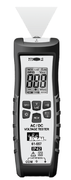
IDEAL 61-557 AC/DC Voltage/Continuity Indicator
Introduction
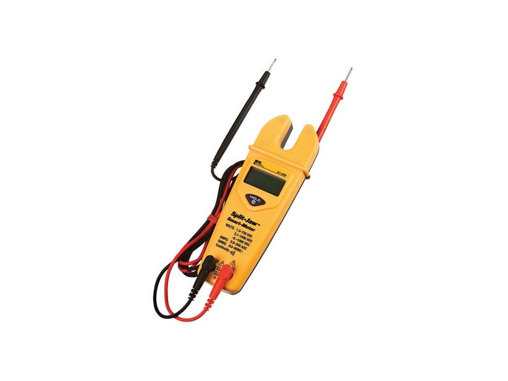
The IDEAL 61-557 Voltage Continuity Tester is an auto ranging average root mean square (ARMS) digital meter that measures AC and DC voltage, Low Impedance AC Voltage (Lo Z) (to reduce the possibility of false readings due to ghost voltages) , and continuity, via test-leads. It detects the presence of voltage between 90V to 600V AC via a non-contact sensor in the top center of the meter. The meter is also capable of performing a GFCI trip test via the probes. The meter also has a flashlight and backlit display.
Arc Flash and Shock Hazard, Proper PPE Required. Follow all safety procedures, wear proper PPE in accordance to NFPA 70E. Read and fully understand the instruction manual prior to using this product. Failure to comply can result in serious injury or death.Contacting IDEAL INDUSTRIES, INC.To contact IDEAL INDUSTRIES, INC., call one of the following telephone numbers:IDEAL Industries USA Customer Service• Phone Number: 800-435-0705• Email: [email protected]
IDEAL Industries Canada Customer Service• Phone Number: 905-683-3400• Email: [email protected]
IDEAL Industries EMEA• Phone Number: +44 (0)1925 444 446• Email: [email protected]
Safety Information
Arc Flash and Shock Hazard, Proper PPE Required. Follow all safety procedures, wear proper PPE in accordance to NFPA 70E and follow the guidelines below and the instructions in this manual when operating the meter. Failure to comply can result in serious injury or death.
- Choking Hazard, Small Parts. Keep Away from Children. Sharp Objects Hazard, This is not a toy. It is not for use or play by children. Keep Away from Children. Failure to do so can result in serious injury.
- Only experienced or technically competent consumers should use this equipment. When in doubt, call an experienced electrician to make any and all necessary repairs or installations. At all times, perform any necessary work on a de-energized circuit that has had its circuit breaker turned off and has been locked out.
- Use the Meter only as specified in this manual or protection provided by the Meter can be compromised.
- Before using or connecting the Meter, visually inspect it to ensure the cases are not cracked and the back case is securely in place. Do not use if the Meter appears damaged.
- Before using the test leads, inspect carefully for damaged insulation, exposed metal or cracked probes. Check test leads for continuity. Do not use leads if they appear damaged.
- Use only approved test leads. Do not use improvised connections that could present a safety hazard.
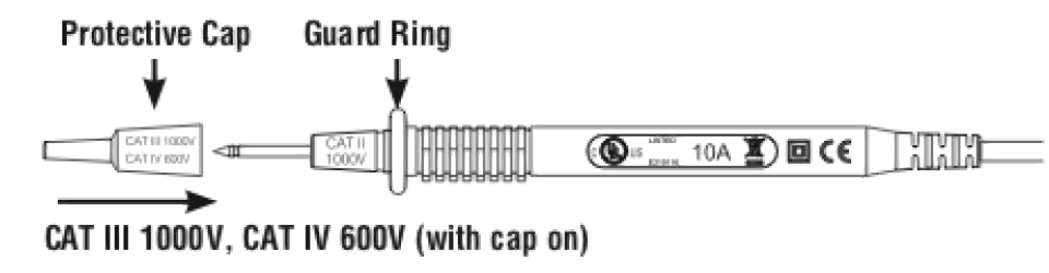
- When measuring, keep fingers behind the Guard Ring. See “Using Test Leads” on pg 11.
- Connect the common test lead before connecting the live test lead. When disconnecting test leads, disconnect the live test lead first.
- This Meter is intended for use by qualified electricians. Follow NFPA 70E Standards for Electrical Safety in the Workplace when using this Meter.
- Do not use without the batteries correctly in place and the battery door closed and secured.
- Do not use Meter if it operates incorrectly as protection may be compromised. When in doubt, have the Meter serviced.
- When servicing the Meter, use only specified replacement parts.
Arc Flash and Shock Hazard, Proper PPE Required. Follow all safety procedures, wear proper PPE in accordance to NFPA 70E and follow the guidelines below and the instructions in this manual when operating the meter. Failure to comply can result in serious injury or death.
- Have the Meter serviced only by qualified service personnel.
- Do not use the Meter around explosive gas, dust, or vapor, or during electrical storms, or in wet environments.
- When measuring, keep fingers behind the Tactile Barrier. See “The Meter” on pg. 8 and 9.
- Do not apply more than the rated voltage, as marked on the Meter, between the terminals or between any terminal and earth ground.
- To avoid false readings that can lead to electrical shock and injury, replace the batteries as soon as the low battery indicator ( ) appears.
- Remove the test leads from the circuit prior to removing the battery door.
- Voltages exceeding 30VAC or 60VDC pose a shock hazard so use caution.
- Always ensure that test leads are secured so that they cannot be accidentally snagged or tripped over.
- Do not work alone so that assistance can be rendered in an emergency.
- Use extreme caution when working around bare conductors or bus bars. Contact with the conductor could result in electric shock.
- Adhere to local and national safety codes. Individual protective equipment must be used to prevent shock and arc blast injury where hazardous live conductors are exposed.
- Never operate the Meter with the back cover removed or the case open.
- These meters are IP42 dust & water resistant. Following any contact with water, thoroughly dry meter and test lead jacks prior to subsequent use.
- Cancer and Reproductive Harm – www.P65Warnings.ca.gov
CAUTION
Meter damage, equipment under test damage or data loss can occur if the following guidelines are not adhered to.
- Use the proper terminals, function, and range for the measurement application.
- Clean the case and accessories with a damp cloth and mild detergents only. Do not use abrasives or solvents. Make sure the meter is completely dry before use.
Symbols & Descriptions
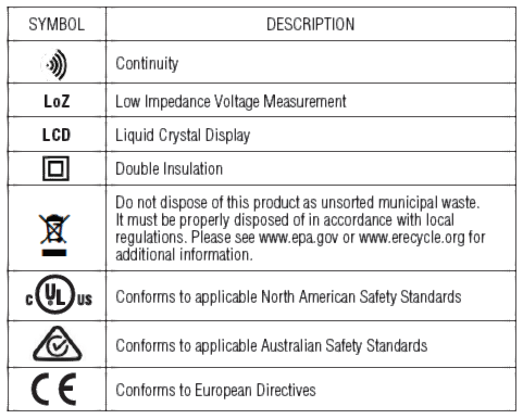
NOTE: The Measurement Category (CAT) and voltage rating of any combination of test probe, test probe accessory, current clamp accessory, and the Meter is the LOWEST rating of any individual component.
Operation
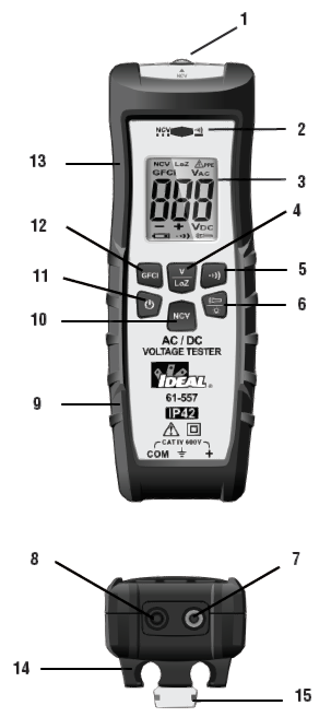
Identification and Description of Operating Controls and Functions for the 61-557 AC/DC Voltage Tester:
- Flashlight/NCV Sensing Point
- NCV/Continuity High Voltage Indicator LED (RED)
- Main Display (LCD)
- VAC VDC LoZ Select Button
- Continuity Select Button
- Flashlight/ Backlight Select Button
- Volts Input Terminal
- COM Input Terminal
- Ergonomic Grip
- NCV Select Button
- On/Off Button
- GFCI Button
- Tactile Barrier
- Probe Holders
- Hanging Strap Clip

Operating Features
High Voltage Warning (HI-V)The meter indicates PPE when measuring > 36V AC on the VAC function and >50V DC when on the VDC function.Auto Power Off (APO) FeatureThe meter automatically beeps 5 times and powers down after 15 minutes of detecting no activity in any of the three following modes; Voltage Test, NCVT, or Continuity.LoZLow impedance measurements defeat the influence of ghost or stray voltages on the displayed value which are often caused by induced voltages coupling from one parallel conductor to the next as found when measuring one conductor in multiple conductor circuits.Caution – Use caution when using the LoZ function on equipment that may be damaged by being connected to a low impedance source.
Backlight / Flashlight
Backlight and flashlight are selectable to be on in all functions.
Press and hold the button on the meter to turn the backlight/flashlight on and off. A short press of the backlight button for less than 1 second will turn the backlight on or off. A long press of more than 3 seconds will power the flashlight on or off. The white backlight and flashlight will remain lit for about 5 minutes before they automatically turn off to conserve battery power. Or turn the lights off by pressing and holding the button again.
Using Test Leads
WARNING: Arc Flash and Shock Hazard, Proper PPE Required. Follow all safety procedures, wear proper PPE in accordance to NFPA 70E and follow the guidelines below and the instructions in this manual when operating the meter with TL-757 Test Leads or equivalent. Test Leads must be rated for the electrical environment the meter is being used in and have a voltage rating of at least the voltage of the circuit to be measured. Failure to comply can result in serious injury or death.
- Choking Hazard, Small Parts. Keep Away from Children. Sharp Objects Hazard, This is not a toy. It is not for use or play by children. Keep Away from Children. Failure to do so can result in serious injury.
- These meters are IP42 dust & water resistant. Following any contact with water, thoroughly dry meter and test lead jacks prior to subsequent use.
NOTE: The 61-557 is only Rated to 600V AC or DC MAX.
WARNING:
- Use only approved test leads. Do not use improvised connections that could present a safety hazard.
- Prior to using the test leads, inspect them carefully for damaged insulation, exposed metal or bent probes. Check test leads for continuity. Do not use leads if they appear damaged.
- When using the probes, keep fingers behind the finger guards on the probes.
- Connect the common test lead before connecting the live test lead. When disconnecting test leads, disconnect the live test lead first.
- Always ensure that test leads are secured so that they cannot be accidentally snagged or tripped over.
This meter is intended for use with the IDEAL TL-757 lead set (provided with this product) or equivalent. The lead set must comply with requirements for Overvoltage and Measurement Categories CAT IV 600V CAT II 1000V.
Meter Operation
Non-Contact Voltage Sensing
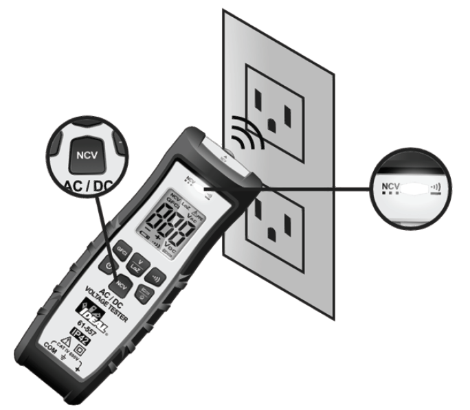
First, turn the meter on and then press the NCV button. Place the NCV tip with NCV close to an AC outlet (or any AC conductor such as light switches or power cords) and scan back and forth across the outlet. The meter beeps On/Off continuously and the Red NCV LED above the display flashes if the sensing antenna detects live voltage greater than 40V AC (50 -60 Hz). Voltages with frequencies higher than 60Hz or electrostatic charges may also be detected by the NCV sensing antenna. Either test lead can also be used to differentiate between the hot and neutral. Plug the red or black test lead into the V input jack on the meter. With the meter in the NCV mode, insert the probe end of just one probe into the slots on the outlet. The meter will beep and the Red LED will flash when a hot conductor is contacted.
NOTE: If both leads are inserted to a live conductor while the 61-557 is in the NCV mode, Err and the PPE warning will flash on and off in the display and an intermittent beep will sound indicating that the unit is contacting live voltage BUT NO voltage will be displayed. Press the V button to read actual voltage.
NOTE: While the NCV is a helpful function, it is ALWAYS RECOMMENDED that the operator verify that any electrical conductor is completely de-energized and that no voltage is present by measuring for voltage AND CONFIRMING THAT NO VOLTAGE IS PRESENT and that all applicable PPE and lock out tag out procedures be followed before attempting any work on ANY electrical distribution system.
Measuring AC or DC Voltage
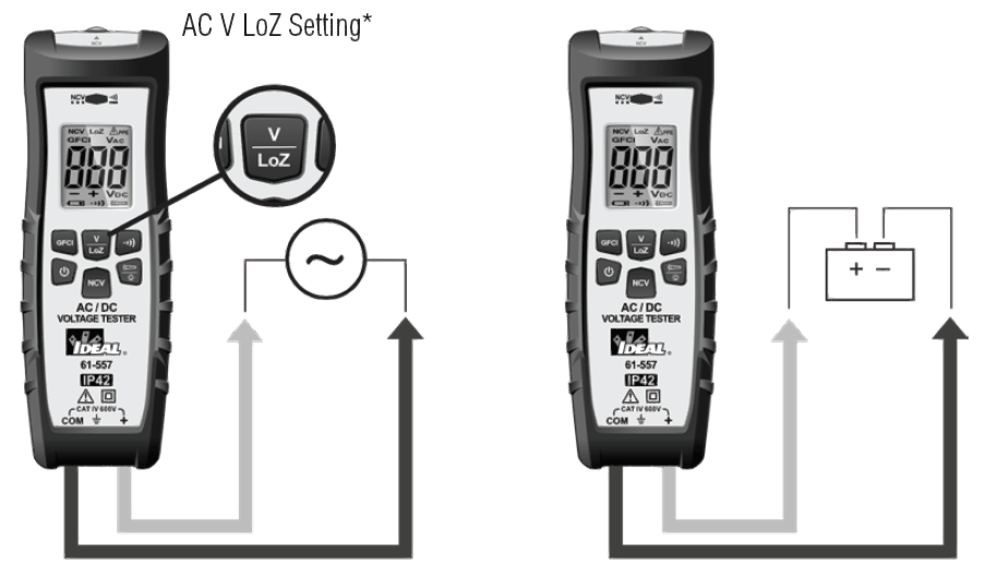
*Note: When measuring AC voltage, Ghost or stray voltages (caused by induced voltages coupling from one parallel conductor to the next as found when measuring one conductor in multiple conductor circuits) may cause an incorrect value. Selecting the Low impedance position (LoZ) on the dial, (see inset above) while measuring voltage with the 61-557 will defeat the influence of Ghost or Stray voltage.The probe holders on the back may be used to correctly space the two probes to access a standard outlet for Voltage measurements between the hot and neutral. Remove the protective caps to expose the probe tips and be sure to reinstall them when finished.

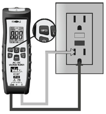
Checking a GFCI
Remove the protective category caps form the ends of the probes. (BE CERTAIN TO REPLACE THESE WHEN YOU ARE FINISHED.)Insert the black probe into the gound slot. Insert the red probe into the small slot (HOT)in the outlet.
Verifying Continuity
- Verify the circuit is de-energized.
- The meter will sense the level of resistance and a beep if the resistance is less than 10 kΩ to confirm that continuity is present.
- Red LED will illuminate, and the continuity icon will remain displayed.

Functions Operation Table
| Button | Response | Default Function | Operation |
| ACV/DCV | ACV | Short press (<1s) for voltage. Long press (>3s) for LoZ. | |
| GFCI | GFCI | Press and hold until GFCI trips, no longer than 7 seconds. | |
| Continuity | Continuity | Press to select. | |
| NCV | NCV | Press to select. | |
| Non-Contact Voltage Indication Displays “NCV” & “EF” |
Functions Indication Table
| Function | Description |
| LCD | 600 count LCD. Displays a “-” symbol for all negative readings, displays “AC” for alternating current or “DC” for direct current. |
| LCD Backlight | White backlight. |
| Flashlight | White flashlight works independently of LCD backlight. |
| High Voltage Alarm | 1) Effective setting: ACV / DCV.
2) In ACV/DCV, voltage measurement value: ACV ³36V/DCV ³50V, LCD displays high voltage and PPE. 3) If 600V AC/DC is exceeded, the LCD displays “OL”, the buzzer beeps On/Off continuously and the high voltage alarm (PPE symbol) is displayed. |
| Over Range Indication |
LCD displays “OL” when over range is encountered. |
| Low Battery Indication | The “ ” symbol appears in the LCD display with insufficient voltage. Then the buzzer beeps for 5 seconds and the unit powers down. This ensures accurate readings. |
| APO | The meter automatically beeps 5 times and powers down after 15 minutes of detecting no activity in any of the three following modes; Voltage Test, NCVT, or Continuity. |
Electrical Specifications
| Function | Range | Resolution | Accuracy |
| 61-557 | ±(a%+b) | ||
| AC Voltage (V) | 600V | 1V | ±(3.0%+2) |
| LoZ ACV (V) | 600V | 1V | ±(3.0%+2) |
| DC Voltage (V) | 600V | 1V | ±(3.0%+2) |
| GFCI (mA) | 6mA~9mA | 102V,>6.0mA | ±(2.0%+5) |
- Overload Protection: 720VRMS
- Accuracy a is % of reading and b is LSD (Least Significant Digit).
| Function | Range | Resolution | Accuracy |
| 61-557 | ±(a%+b) | ||
| Continuity | 1.0 Ù | £10kÙ : Buzzer beeps and red indicator LED illuminates continuously | |
| ³15kÙ : No buzzer beep | |||
| NCV | 90-600V | 90V/(50 to 60Hz), with direct wire contact, red indicator LED flashes at a frequency of 3Hz , and the buzzer beeps continuously |
Environmental Specifications
| Operating Temperature: | 32ºF to 104ºF (0ºC to 40ºC) (<80%RH) |
| Operating Altitude: | 6500 ft (2000 m) |
| Storage Temperature: | 14ºF to 122ºF (-10ºC to 50ºC) (<80%RH) |
Intended for indoor use.
Mechanical Specifications
| Dimensions: (L x W x H) | 6.5 in. x 2.25 in. x 2 in. (160 mm. x 55 mm. x 50.8 mm.) |
| Weight: | 0.3 LBS (0.2 KG) |
| Display: | LCD |
| Display Count: | 600 |
| Power Source: | 3 x 1.5V AAA |
| Battery Life: | 100 Hours Typical |
| Ingress Protection Rating | IP42 dust and water resistant |
EMC/EMI
CISPR 22 3rd Edition. Class B Limits.EN 55032CISPR 32CISPR 11FCC 15. 107 with reference to Section 15.109 (g).ICES-003EN 61326-2-2 Sec 6.4.2.101
USA (FCC)47 CFR 15 subpart B. This product is considered an exempt device perclause 15.103.
SafetyComplies with the following:IEC 61010-1, Edition 3 (2010-06) +AMD1 (2016-12)ANSI/UL/IEC EN 61010-1, Edition 3 (2016-04-29)CSA-C22.2 No. 61010-1-12 Edition 3 (2019-07-19)IEC 61010-031 Hand-held Probe Assemblies (2015-05)+AMD1(2018-05)IEC 61010-2-033 (2019-06)UL1436Overvoltage CAT IV 600V.Any voltages exceeding the defined maximum voltage measurement categories described above are outside the normal use of the equipment and protection cannot be guaranteed.Pollution Degree Class 2
Maintenance and Service
Equipment Maintenance and Service
Meter InspectionDo not use if meter appears damaged. Visually inspect the meter to ensure case is not cracked.
Test Lead InspectionInspect and replace test leads if insulation is damaged, metal is exposed, or probes are cracked. Pay particular attention to the insulation surrounding the connectors.
Battery Inspection/ReplacementInspect the battery compartment monthly for any signs of degradation. Low battery voltages will cause inaccuracies in readings. Remove the batteries for storage or if the meter will not be used for longer than one month. Battery leakage will compromise the safety of the meter and cause irreparable damage to internal components.
Shock Hazard. Remove the test leads from the circuit prior to removing the battery cover. Failure to comply can result in serious injury or death.
Maintenance and Storage
Switch off and disconnect the meter completely before carrying out any maintenance. Clean the case with a damp cloth and mild detergent. Do not use abrasives or solvents. Keep away from liquids and ensure the meter is completely dry before use.
Service and Replacement PartsThis unit has no user-serviceable parts.
Disposal of Waste, Electrical & Electronic Equipment
In order to preserve, protect and improve the quality of the environment, protect human health and utilize natural resources prudently and rationally, the user should return unserviceable product to relevant facilities in accordance with statutory regulations. The crossed-out wheeled bin indicates the product needs to be disposed separately and not as municipal waste.Do not dispose of this product as unsorted municipal waste. It must be properly disposed of in accordance with local regulations. Please see www.epa.gov or www.erecycle.org for additional information.
Disposal of Used Batteries/Accumulators
The user is legally obliged to return used batteries and accumulators. Disposing used batteries in household waste is prohibited! Batteries/accumulators containing hazardous substances are marked with the crossed-out wheeled bin. The symbol indicates that the product is forbidden to be disposed via domestic refuse. The chemical symbols for the respective hazardous substances are Cd = Cadmium, Hg = Mercury, Pb = Lead.
You can return used batteries/accumulators free of charge to any collecting point of your local authority, our stores, or where batteries/accumulators are sold. Consequently, you must comply with your legal obligations and contribute to environmental protection.
TWO YEAR LIMITED WARRANTY
This tester is warranted to the original purchaser against defects in material and workmanship for a period of two (2) years from date of purchase. With proof of purchase from an authorized IDEAL distributor, a defective tester will be repaired or replaced with the same product or a functionally equivalent product, at the option of IDEAL INDUSTRIES, INC. during the warranty period, subject to verification of the defect or malfunction. Warranty does not cover consumables such as fuses, batteries, and excludes defects caused by leakage from batteries, abuse, mishandling, dropping, ordinary wear and tear, misuse, neglect, unauthorized repair, improper use, alterations, accidents or any causes beyond IDEAL’s reasonable control. Consequential or incidental damages are not recoverable under this warranty. Some states do not allow the exclusion or limitation of incidental or consequential damages, so the above limitation or exclusion may not apply to you. This LIMITED WARRANTY gives you specific legal rights, which vary from state to state. This warranty constitutes the sole and exclusive remedy of the purchaser and the exclusive liability of IDEAL, and is in lieu of any and all other warranties, and expressly disclaims all other warranties, implied, or statutory as to merchantability, fitness for purpose sold, description, quality productiveness, or any other matter. No agent, distributor or other supplier has the authority to modify or amend this warranty or make other representations or warranties other than those contained in this warranty without express written authorization from IDEAL. For warranty service, call IDEAL customer service at 1-800-435-0705.
Scan the barcode on the right to see the new IDEAL T&M Product Line
report this ad
References
[xyz-ips snippet=”download-snippet”]