
![]() STANDALONE CONTROLLERQuick Installation Guide
STANDALONE CONTROLLERQuick Installation Guide

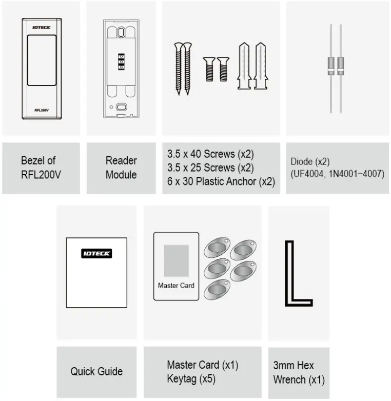
WHAT’S INCLUDED
Please unpack and check the contents of the box. If any of these parts are missing, please contact a nearby distributor or IDTECK.
RFL200V Parts
CABLE CODED & WIRING TABLE
RFL200V Cable coded & Wiring table
| Signal | Color |
| Main Power (+12V) | Red |
| Power Ground (GND) | Black |
| Aux Input #1(Select a Lock Type) | Yellow |
| Door Contact Sensor | Blue |
| Exit Button | Green |
| Alarm Out | Purple |
| Door Lock Out | White |
| Tamper Output (COM) | Pink |
| Tamper Output (NC) | Light Yellow |
| Not Connected | Gray |
| Not Connected | Orange |
| Not Connected | Brown |
INSTALLATION
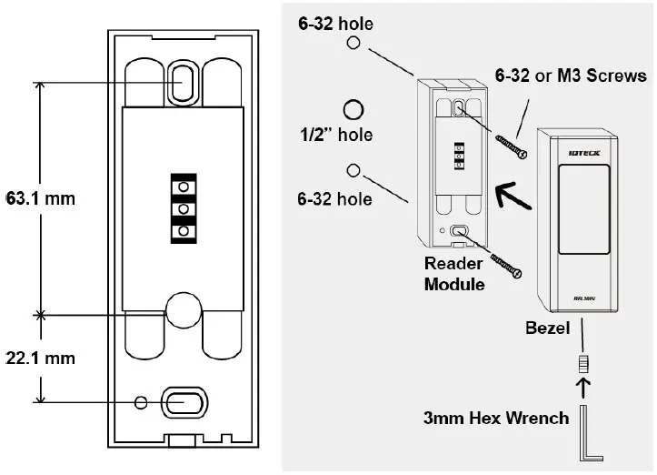
- Drill a 1/2-inch (12.7 mm) hole on to the center of the door frame or the wall where RFL200V is installed, which makes room for the cable of the reader module.
- Drill a 6-32 inch hole at the 43.1mm point straight higher from the center hole and at 22.1mm straight Lower, respectively.
- Insert the reader module into the appearance case and tighten the screw(M6 X 8mm) using the hex wrench.
Input / Output CONNECTION
4-1 Input Connection
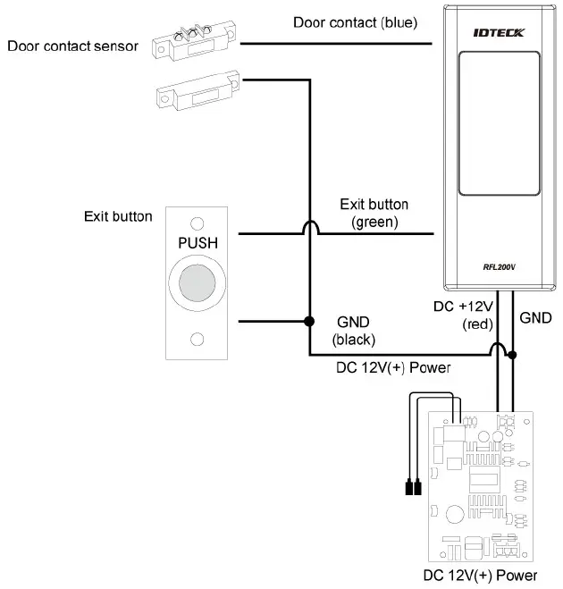
To Connect the power supply unit
- Connect the DC+12V to the red line.
- Connect GND to the black line.
To Connect the Door Contact Sensor
- Connect the COM port of the sensor to the blue line.
- Connect the NO port of the sensor with the GND line.
To connect the Exit Button
- Connect on the end of the button to the green line.
- Connect the other end of the button to the GND.
4-2 Output connection 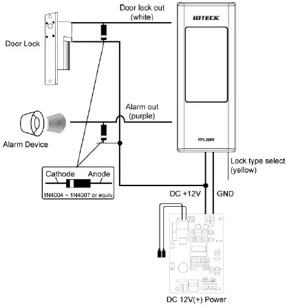 To Connect the power supply unit
- Connect the DC+12V to the red line.
- Connect GND to the black line.
To Connect the Door lock device
- Connect the plus(+) line of the lock device to DC+12V.
- Connect the Minus(-) line of the lock device to the white line.
To connect the alarm device
- Connect plus(+) line of the alarm device to DC+12V.
- Connect the minus(-) line of the alarm device to the purple line.
To specify the lock type
- POWER FAIL SAFE: Connect the yellow line to GND.
- POWER FAIL SECURE: Leave the yellow line in the floating state.
Product manual download information
This Quick Installation Guide is a manual to provide the product’s basic installation information only. If you need all the information of the product, please download detailed manual following the steps specified below.
For registered users of our homepage
- Visit IDTECK’s homepage (www.idteck.com).
- Click the Sign-in button at the top of the homepage and log in using your registered ID and P/W.
- Click the ‘PRODUCT’ menu on the main page of our website and select the product that you wish to download a manual for.
- At the bottom part of the product page, you selected, click the “DOWNLOAD” button and download the manual.
For unregistered users of our homepage
- Visit IDTECK’s homepage (www.idteck.com).
- Please click the “Member Join” menu at the top of our homepage and register your details following the registration process.
- You can use your ID and P/W after the web administrator approves it. Once it’s approved, then please refer to “For registered users of our homepage” above.Please contact us as below if you have any inquiries or issues arise.
IDTECK Headquarter5F, Ace Techno Tower B/D, 684-1, Deungchon-Dong,Gangseo-Gu, Seoul, 157-030, KoreaTel: +82-2-2659-0055Fax: +82-2-2659-0086E-mail: [email protected]Website: www.idteck.com
Memo

The specifications contained in this manual are subject to change without notice at any time.5F, Ace Techno Tower B/D, 684-1, Deungchon-Dong,Gangseo-Gu, Seoul, 157-030, KoreaTel : +82-2-2659-0055Fax : +82-2-2659-0086E-mail: [email protected]April. 2014 Copyright ©2014 IDTECK Co., Ltd.FFQG0194 April.
References
[xyz-ips snippet=”download-snippet”]