
imperii Brake and Turn Signal Transmitter Instruction Manual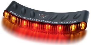
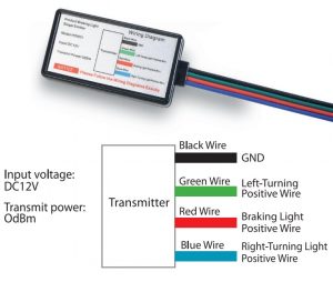
Description of brake and steering signal emitter:
The emitter comprises a junction on box, four different colors of wires led form the junction box are respectively connected witch corresponding wires on a motorcycle. The emitter and wire connection are shown in the figure.
Description of brake and steering signal receiver:
 Red brake signal lights
3M adhesive tape on the back and stick the receiver on the rear part of a helmet.
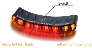
- The receiver is provided with eight high-brightness LED light beads, where in the two yellow light beads on right are left turn lights, the four red light beads in the middle are brake signal lights.
- The receiver is provided with one key switch, particularly a On -light – Off one – key switch. When the receiver is turned on, all the signal lights of the receiver flash twice to enter the On state; in night light mode, the brake signal lights flash three times quickly every 2 seconds to play the warning role during night driving; and when the receiver is turned off, all the signal lights of the receiver flash once to enter Off state.
- The emitter and receiver have code matching function used when the receiver or the emitter needs changing. Long press the key of the receiver for 5 seconds, all the signal lights of the receiver flash and enter the code matching state; press the brake lever of the motorcycle to brake, and finish the code matching when the brake signal lights on the receiver lights up.
- The receiver is powered by two 7# batteries with average service life of about one mouth. Install the batteries all the bottom of the receiver.

imperii Brake and Turn Signal Transmitter Instruction Manual – imperii Brake and Turn Signal Transmitter Instruction Manual – imperii Brake and Turn Signal Transmitter Instruction Manual –
[xyz-ips snippet=”download-snippet”]