
Infitary Solar tire pressure monitoring system Instruction Manual

Operating instructions| Important: Please read the instruction manual carefully before use.The schematic diagrams of this manual are for reference only, whichever is subject to the actual product.
Please turn on the power of the host before installation.
Product Overview
Thanks for purchasing our tire pressure monitoring system T i r e P r e s s u r e M o n i t o r i n g S y s t e m ( T P M S ). This system is designed to provide you with more protection while driving, and it will alert the car tires in advance.With the T P M S installed, the system monitors tire pressure and temperature conditions in real time. If any abnormal tire pressure and temperature are detected, the system will send a warning sound and a bright flashing icon to inform the driver in real time. Real-time reminders and handling ofproblems can avoid traffic accidents and ensure the safety of drivers and passengers. In addition, the installation of the system can effectively improve vehicle comfort, improve driving safety, reduce vehicle wear, reduce fuel consumption and prevent the occurrence of punctures.Please read the instruction manual before using this product. If you have any questions, please contact the purchaser or call customer service. Thank you!
1, F C C considerations
This system has complied with the requirements of Article 15 of the US F C C regulations, but the following precautions must be met when operating:1.1 This product may not operate due to other harmful interference.1.2 The abnormal operation of this system may cause the system to fail.1.3 This system has been tested by the instrument and complies with the limits of the digital C a s s B. These limits are designed to provide meaningful protection against interference sources in residential areas, in accordance with F C C Article 15. Such devices will generate wireless RF signals that, if not installed and properly used, will cause some sources to interfere with wireless communications. However, even if it is properly installed, it cannot be completely ensured that no interference will occur. If this product interferes with the reception of the radio or television, it is up to the user to decide whether to turn off the product. Users can also adjust the correct frequency to solve the problem. Possible methods are as follows:A, re-adjust the antenna B, increase the distance between the device and the system C, change the position and connection of the receiver2, product use precautions2. Please pay attention to safety during driving, do not operate and observe the system frequently.2 . 2 This system uses the sensor transmitter to measure the pressure and temperature in the tire and transmit it by radio signal. During normal operation, the receiver will receive the normal tire pressure and temperature with specific values. When any one or more of the sensor transmitters detects that the tire is at an abnormal tire pressure or tire temperature, the sensor transmitter will immediately transmit an alarm signal to the wireless tire pressure monitoring system in the vehicle. When the receiver receives an abnormal tire After the signal, the corresponding tire abnormality will be issued immediately and the driver will be notified by corresponding alarm icon, text or voice and corresponding tire pressure and temperature values. The driver should immediately check and repair the tire to avoid the tire. Accidents occur due to problems such as improper tire pressure or high temperature.2.3 General tires will have a natural micro-leakage phenomenon, and the pressure of the tire will decrease with time. This is a normal phenomenon and is not directly related to the installation of this product.2.4 During the driving process, due to the thermal expansion and contraction of the air, the air pressure is high and low. This is a normal phenomenon and is not directly related to the installation of this product.2. 5 Improper installation of this system will affect the use of this product or cause damage to the product. Always hire an experienced tire installation technician to install it. Be careful not to damage the sensor transmitter when you need to disassemble the tire again. The valve with built-in sensor transmitter is not suitable for repeated disassembly and assembly.2. 6 Use a specially configured power cord, and the power cord cannot be bundled around the receiver. Failure to do so will damage the machine oraffect signal reception and will not be covered by a free warranty.
2. 7 80% of D V D equipment, multi-function rearview mirrors or other high-power equipment on the market have electromagnetic interference. It is recommended that the receiver be more than 50 C M from such products, so as not to affect the stability of the receiving signal. The best use position in the car is the upper left corner of the A-pillar front, the upper right corner, and the middle of the front two seats (away from the central control).2. 8 All information on the product performance, specifications, warranty information, etc. are subject to change without notice. certain special environmental conditions, the system may cause the wireless signal to be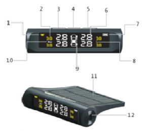 weakened or the signal is not received due to interference factors or incorrect operation methods or improper installation methods. When the signal of a certain tire is not received in 0 minutes, the car should be away from the current position (possibly with strong wireless signal interference nearby) or go to the designated tire warranty factory as soon as possible to check whether the sensor in the tire is faulty or tire. The battery of the internal sensor is exhausted (the battery may be constantly abnormal due to abnormal conditions, and it is necessary to continuously transmit radio waves to warn the driver that the battery life is shorter than the normal service life).installation methods and the system is installed by qualified operators in accordance with the steps in the installation manual. The system can operate correctly and provide warranty. Product warranty will no longer be available if the sensor is damaged due to improper installation or disassembly. This system is suitable for (M1The N1 model uses four tires, including a car, a commercial vehicle, an off-road vehicle, a jeep, and a van, and the tires use a model with a maximum pressure of less than 8 Bar (gauge pressure).l It is recommended to replace or inspect the “tire valve” regularly every year to avoid air leaks in the tire valve.1, solar charging 2, tire temperature display 3, left button 4, menu button 5, right button 6, tire pressure display7, battery display 8, temperature display 9, tire position 10, pressure unit 11, solar charging board 12, USB charging port2, button function descriptionUSB charging port / receiver charging interfaceLeft button / left to switch menu (in standby mode, short press to adjust brightness, long press on and off)M M Menu button/confirm button (standby mode, long press to enter menu mode, select the parameter to be adjusted, short press once toconfirm) Right button/right to switch menu (in standby mode, short press to adjust brightness)3. Abnormal/alarm information
3.1 3.1 leakage warning
When the air pressure of any tire is less than 1.8 bar in one launch cycle, the buzzer will sound an alarm promptly, and the corresponding tire iconand pressure data and the TPMS icon and the air leak icon will flash continuously. Press and hold the right button to stop the buzzer alarm; stop Thealarm is released after the air leak.3.2 low pressure alarmWhen it is detected that any tire pressure is lower than 75% of the standard tire pressure, the buzzer sounds an alarm, and the corresponding tire iconand pressure data and the TPMS icon and the low pressure icon continuously flash, when the tire pressure is equal to or higher than the alarmthreshold. The alarm is released; the default setting of the low-pressure alarm threshold is 1.8 Bar, which is suitable for all cars (reference file:GB/T2978-2008 car tire specifications, size, air pressure and load). For different models, please refer to the car doorpost. The standard value of thetire pressure is adjusted after consultation with the tire shop or 4S shop.
3. 3 high voltage alarm
When it is detected that any tire pressure is higher than the standard tire pressure value of the cold tire when the vehicle is fully loaded, the buzzersounds, and the corresponding tire icon and pressure data and the TPMS icon and the high pressure icon continuously flash, when the tire pressure islower than The alarm is released after the alarm threshold is 0.1 Bar; the factory setting of the high-pressure alarm threshold is defaulted to3.2Bar, suitable for all cars (reference file: GB/T2978-2008 car tire specifications, size, pressure and load), for different models, please refer to thetire pressure standard value on the car door column or to the tire shop, 4S Shop adjustment after consultation.3. 4 high temperature alarmWhen it is detected that any tire temperature is higher than the preset temperature threshold, the buzzer sounds an alarm, and the corresponding tireicon and temperature data and the TPMS icon and the high temperature icon continuously flash, and the alarm is generated when the temperature islower than the alarm threshold by 1 °C. Released; the factory default setting for temperature threshold is 70 °C.
3.5 sensor low battery alarm
When the battery level of any sensor transmitter is lower than 2.4V, the buzzer will sound an alarm, and the corresponding tire pressure icon and low battery icon will flash continuously. Each time it is restarted, it will only alarm for the first time. After 30 seconds, the alarm will be automatically eliminated
the function settings
The user can set the parameters according to the condition of the vehicle or the actual needs. If the settings are not modified, the system defaults to the factory state;Press and hold the “Menu” button for 3 seconds to enter the system setting state. Except that the pairing operation interface is 90 seconds, the other interface will not exit any operation within 30 seconds. The system will automatically exit to the main interface state. The setting without confirmation will not be possible. save.(No matter which parameter is set, long press “Menu” after setting is completed to return to the main interface)

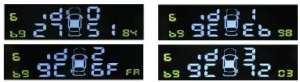
press the “menu button” to enter the operable setting state, select the PSi unit through the “left and right button”, and select the required unit identifier.After that, press the “Menu” button to complete the setup. (Refer to Figure 1)
In the standby state, press and hold the “menu button” for 3 seconds to enter the system setting state. Press the “right button” once to enter the temperature unit setting, press the “menu button” to enter the operable setting state, select the °F unit by the “left and right button”, select After the required unit ID, press the “Menu” button to complete the setup. (Refer to Figure 2)2, change the upper and lower limits of the tire pressure value (factory default is high pressure 3.2 Bar / low pressure 1.8 Bar, high temperature 70oC) In the standby state, press and hold the “menu button” for 3 seconds to enter the system setting state, press “right button” 2 times to enter the air pressure upper limit setting.Short press the “Menu” button once, the air pressure number will flash. At this time, you can set the maximum upper limit air pressure by “left and right button”. After the setting is completed, press and hold the “Menu” button to exit. (Refer to Figure 3)In the standby state, press and hold the “menu button” for 3 seconds to enter the system setting state, press “right button” 3 times to enter the lower air pressure setting. Short press the “menu button” once, the air pressure number flashes, set the air pressure lower limit parameter value by “left and right button”, press the “menu button” to exit after the setting is completed.(Refer to Figure 4) In the standby state, press and hold the “menu button” for 3 seconds to enter the system setting state, press “right button” 4 times to enter the temperature alarm setting.Press “Menu” 1 and the temperature number will flash. At this time, set the temperature alarm value by “left and right button”. After the setting is completed, press “Menu” to save. (Refer to Figure 5)

3, Quick pairing
In the power on state, press and hold the middle button for 3 seconds to enter the setting, press the left button again to enter the seventh item, press the middle button twice, the machine resets and restarts, restores the factory settings, and then the sensor is loaded into the valve in sequence. On the mouth, drive the car up to speeds of more than 30 kilometers, about 5-10 minutes, the host will automatically find the sensor signal, and all four sensors will be found to complete the pairing.After the factory reset, the previously manually set data will be restored to the factory settings.

4, set the tire pairing (charge / deflation pairing)In the standby state, press and hold the “menu button” for 3 seconds to enter the system setting state. Press the “left button” twice to enter the pairing selection mode and press the “menu button” once, as shown below:
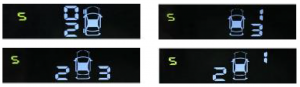
At this time, the number of the interface 0 appears to be jittered. The default is the state of the left front wheel pairing. Press the “menu key” once, and the ID code in the lower left corner is flashing. The pairing modes are: Select the four positions of “Left Front”->“Right Front”->“Left Rear”->“Right Rear” and perform pairing learning of the tire sensor. When the desired paired tire position is selected, only the screen is displayed. The tire “ID” code keeps flashing. Each pair of tires must be confirmed by pressing the “Menu” button once, indicating that the sensor of the tire is activated.(The built-in sensor uses the method of charging and discharging, the external sensor uses the repeated installation to activate the sensor to transmit the signal.) When the receiver receives the signal from the corresponding sensor, the new “ID” code will be displayed in the lower left corner, indicating that the sensor has been The host successfully paired. (Note: 0 means left front wheel /1 means right front wheel /2 means left rear wheel /3 means right rear wheel).
5, tire exchangeIn the standby state, press and hold the “menu button” for 3 seconds to enter the system setting state. Continue to press the “right selection button” 5 times to enter the tire exchange mode. Press the “menu button” once to confirm the entry into the tire exchange mode. There are two tire icons. Keep blinking, short press the left or right “Selection button” to enter the tire exchange operation. The default is “Replace the left front wheel and the right front wheel”. Press the “left and right selection keys” to switch from the “left front wheel and the right front wheel” respectively. > “Left rear and right rear wheel exchange” -> “Left front and left rear wheel exchange” -> “Right front and right rear wheel exchange” -> “Right front and left rearwheel exchange “->” The left rear wheel and the right rear wheel are exchanged. “Select one by one, and press the “Menu key” once in any two rounds to change the combination state.” The conversion is successful. (Note: 0 means the left front wheel / 1 means the right front wheel / 2 means left. Rear wheel / 3 means right rear wheel)
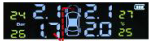
6, alarm status diagramWhen buzzer or voice alarm, long press the right button to turn off the alarm sound (if the alarm is not released when the next data update, it will alarm again.Low tire pressure alarmLeft rear wheel air pressure low alarm, icon: The icon flashes, the left rear tire pressure flashesThe left rear tire pressure is abnormal, and the parking is checked in time to eliminate the fault.Blinking (Note: Voice version prompt: “Lower rear tire is depressed”)
High tire pressure alarmLeft rear wheel air pressure low alarm, icon: The icon flashes, the left rear tire pressure flashesTire pressure is too high, please deflate the tires in time
Blinking (Note: Voice version prompt: “Left rear tire pressure”)Exceeding the high temperature alarm value, the left rear tire temperature is high, the icon flashes, and the left rear wheel temperature flashes.The sensor is low (battery is exhausted)The sensor is low, the icon is: the left rear wheel sensor is out of power.The receiver is low on battery. Illustration: Receiver is out of power. Icon flashes.
Blinking (Note: Voice version prompt: “Left rear wheel is low”)Blinking (Note: Voice version prompt: “Receiver is low”四、 parameters and warranty
- tire pressure technical parameters
- warranty terms
The one-year product warranty is guaranteed for one year from the date of purchase (consumable parts and accessories that need to be replaced regularly) are not included here. During the warranty period, if the product fails under normal use, the company will provide replacement or repair free of charge; the company reserves the right to replace other new products or products of equal value. The original warranty cannot be provided if:
- The product is not operated in accordance with the instruction manual;
- When the product is abused or misused due to accident or negligence and is damaged;
- When the company or the company’s authorized maintenance department repairs and causes damage;
- Damage caused by transportation;
- Other failures or damages caused by non-product design, technology, manufacturing, quality and other issues.
All faulty items must be sent to the company or our authorized service department for repair, with details of the fault and the original purchase invoice.This warranty is valid in countries where it is purchased locally.This warranty is limited to the conditions described herein and the company will not be liable for any special, minor or consequential damages in connection with the sale of this product.This warranty provides you with specific legal rights, but may also have other rights that vary from country to country.The color of the product provided in this sales package may differ from the color shown on this manual or on the package. the image is only a reference,Specifications are subject to change without notice. Parts supply may vary by market, please check with your local agent. Installation Notes External sensor installation
 a. Screw in the anti-theft nut first
 c. Screw the anti-theft nut counterclockwise against the sensor wrench
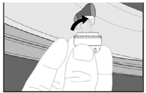 b. tighten the sensor
 d. Tighten the sensor and tighten the anti-theft nut counterclockwise with a

When replacing the battery with the sensor, please disassemble one by one, install the outer casing, do not mix or disassemble and install at the same time;It can effectively prevent the sensor from being misplaced and installed in other tire positions due to misassembly of the housing.When the receiver prompts “The sensor is low”, and the display shows a LO flashing warning Please replace the sensor battery on the corresponding tire in time.
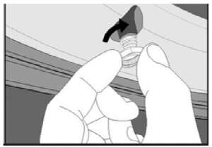
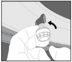
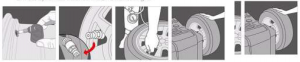
Internal Sensor Installation
I .0:Ifkrirtile hie ant) rsn. 2. Cut off the rubber at the bu;….11 of 3. Use screw to fix vatvc a 61, remove the washer, nut and dust cap. 4. Mount the sensce on the vatve, adjust the best sensor angle in the wheel nub by hand. Remove the sensor horn wheel hub. Use a speciakieci toot to tighten the vatve on the same location.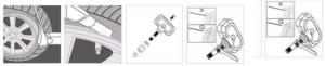
5. After tighten the valve, mount on tne wive’ hub.6. Mount the washer nut and dust cap.7. Mount the tire and nrn, inflate the pre again.8. Test dynamitic balance mat& balance wjht.
Read More About This Manual & Download PDF:
[xyz-ips snippet=”download-snippet”]