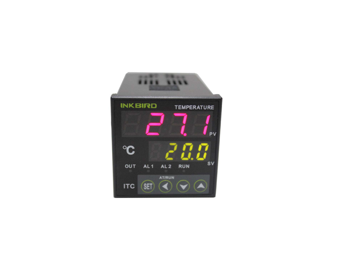
INKBIRD PID Temperature Controller User Manual
1. Safety Precautions
• Ensure the product Is using within the specification.• Do not touch th11 terminals al least while power is being supplied. Doing so may occasionally result in injury due to electric shock.• Do not allow pieces of metal, wire clippings, or fine metallic shaving or flllngs from installation to enter 1h11 product. Doing so may occ11sion11lly result in electric shock, fire, or malfunction.• Do not use 1h11 product where subject to flElmmable or explosive gE1s. ClherwisEI, injury from explosion may occasionally occur.• Never disassemble, modify or repair the product or touch any of the internal parts. Electric Shock, fire, or malfunction may occasionally occur.• The max current of this controller Is 15A. As for the U.S. and Canada AC 120V, the controller’s load power limit is 1 BDOW. The sensor must be in the controlled object when running the controller. Otherwise. the temperature of the controller will be low even If the controlled object Is heating. Then the controller will provide heater with full power which may cause the controller over-heat. damage the device and even cause fire Any abnormal Indication or noise Is being observed, turn off the controller, unplug the power, and contact the manufacturer before reusing.
2. Technical parameter
|
|
Heat:15A for 120V AC, 12A for 220V AC |
| Heat output | Built-in optical isolated SSR of the output switch device with no-voltage crossbar switch. |
| Pump output | Relay output: AC 250V 8A (resistance load) Relay electric life: 100000 times |
| Character display | PV/SV: 14.2mm character height red high light LED |
| Sensor Type | NTC sensor (R25 ºC=10KΩ) |
| Probe cable length | 6.5 ft (2 meter) |
| Temperature resolution | 0.1ºC or 0.1 ºF |
| Temperature Control Range | -50~125°C / -58~257°F
|
3. Panel Instruction
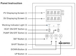
- PV Displaying Screen: Display the measuring value or the setting parameters.
- SV Displaying Screen: Display setting value or the set parameters readout.
- Working Indicator Light HEAT: Control Output Indicating ALARM: Alarm Indicating
- HEAT ON/OFF Button:Press it to turn on the heating output, the green lamp is on, and then press again to turn the heating output off , the green lamp is off.
- PUMP ON/OFF Button: Press it to turn on the pump output, the green lamp is on, then press it again to turn pump output off, the green lamp is off.
- SET Button: Press this button can read the value of control output and the set temperature. Hold and press this SET button for 3s or more will enter into the parameters settings mode.
- SHIFT BUTTON: When setting the value or parameters,A, Press this button will switch to the required value position.B, Press this button will shift to the sub menu from the main menu.C, Press this button can be freely switching to another mode from manual or the automatic operation.
- DOWN Button: When setting the value, pressing the down button can be decrease the value that would be reduced rapidly by keeping press this button.
- UP Button: When setting the value, pressing the up button can be increase the value that would be added rapidly by keeping press this button.
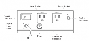
Flank Panel
4. Dlsplay Modes
4.1 Display Modes
Note: Please get the flow charts In the following page,ProbeInterface
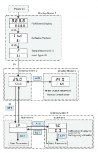
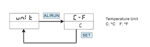
- Display Model 1: When power on. with all LED displaying, and the version numberof the software will display 1 second later_ Then 1 second later. dlsplaytemperature unitsuch as C in display 1: temperature unit =°C, display F =”F.
- Display Mode 2: In operating mode, PV displays current temperature value. SV displays satting velue.
- Display Mode 3: Pren the shift button for 3 seconds to switch to the manual output mode, preH the button again to switch back to the automatic output mode.
- Display Mode 4: Press SET for 3 seconds to enter Into main menu, displaying with the parameters type: press shift button to enter Into submenu to change parameters setting,for the detailed parameter definition. please see table 3 or selling flow chart.
4.2 Operation Instruction4.2.1 Change Setting Value (SV}
Press. ![]() T button then release, there will be flickering decimal point in the lower right corner at far-right of the SV setting value, then press.
T button then release, there will be flickering decimal point in the lower right corner at far-right of the SV setting value, then press. ![]() button to change the value; ifneed to change to larger value, then press the shift button to move the flickering decimal point to the position of the desired value, or press and hold.
button to change the value; ifneed to change to larger value, then press the shift button to move the flickering decimal point to the position of the desired value, or press and hold. ![]() Tbutlon to get the desiredvalu11 with r11pidly changing: then pres a SET button to Hve 1ha changed value, the flickering decimal point will lurn off and operate. The controller will automatically save the changed value and operate after 1 S seconds without any operation of the SET button or other buttons.
Tbutlon to get the desiredvalu11 with r11pidly changing: then pres a SET button to Hve 1ha changed value, the flickering decimal point will lurn off and operate. The controller will automatically save the changed value and operate after 1 S seconds without any operation of the SET button or other buttons.
4.2.2 Change Dlsplaylng Mode
Display mode 2: in automatic running stale, PV displays current temperature. SV displays set temperature; press AIM button for 3 seconds to enter display mode 3, PV displayscurrent temperature. SV displays setting value of output. If you press the button again, it will return to display mode 2.
4.2.3Automatic Mode/Manual Mode Conversion
Press the AIM (switch) button for 3 seconds to switch to the automatic or manual mode_ If you switch to Iha manual mode, the leftmost side of the SV will di a play M (eg: MO-M100).In this mode, the output value can be set arbitrarily.
4.2.4 Self.tuning
The factory defaults setting is fuzzy PIO control mode, if need to change to self-tuning mode, then enter into the menu to sal11ct OP (output typ11)- Ctrl (control mode)-AI (Self-tuning).When in aelf-tuning, the temperature may exceed the setting temperature value (will be different value with different heating system) with On-Off controlling. At this time, there willbe alternate displaying In SV {setting value) and “AT• value until the self-tuning finished.
5. Parameter Setting
 Nola: You can get the detailed setting instructions in the following content according to the direction In the Note column.
5.1 Setup Flow Chart

5.2 Input Parameters Setting
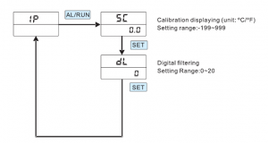
2) Calibration Displaying SC
And this can be calibrated by setting SC parameter with the range of-1g9-9g9,:; or’ F. the formula: actual temperature -measuring temperature= SC setting value. This can be set at room temperature status. e.g .• Ensure there is default SC value before calibrating. lfihe actual temperature room temperature is 25°C, but the controlling measuring the 1amparatura at 20°G, than sat SC to s_o•c as the formula: 2s•c-20°C=s•c_
3) Digital Filtering DL
There Is the built-In digital filtering system of the temperature controller. If there Is displaying with the frequent changing temperature values caused by the Input Interference,this dL can be s11t to gal the stable average value. dL=0-20, Iha largerdL value set, the more stable measuring value will get, but also the slower response. If there is no interference from working environment, then the dL value can be increased gradually until the Instant alteration of the measuring values within 2-5 units. When verifying the instruments, the dL value should be set lo Oto speed up the response.
1) Control Mode Ctrl
- PIO: default control mode, can be used al the first using, if there is not the controlling accuracy required. then can be changed to Self-tuning mode .
- AT: Self-tuning control mode, can be aetwhen there is not the required controlling accuracy by PID control mode. then the controller will be changed lo on-off controlling. After 2-3 iimes switch actions of the temperature controlling, the microprocessor will analyze period. amplitude and osclllatlon wave caused by on-off control. then calculate lhe optimum parameter value. When in self-tuning. the temperature may exceed the setting temperature. and cause alarm, but therewlll be different value with different heating system. If there is not the required temperature value after self-tuning, then try to change the PID initial value before the self-tuning. or restart the self-tuning_
- R: Reset to Factory Defaults, the PIO parameters will be recovered to 1he defaults. After set the R, the self-tuning can be activated by pressing the shift button for more than 3 seconds, same operation as setting the AT to activate the self-tuning. After the self-tuning, Iha controller will be automatically enter Into the PID setting, there Is the optimal parameters saved after the sail-tuning.
- ON/OFF: On-Off Control, same as the mechanlcal thermostat, used In general controlling. The heating (cooling) will turn off when the temperature res ch the set-point (settemperature value+ temperature hysteresis value): and the heating (cooling) will turn on when the temperature drop to the set-point (sat temperature value – temperalur11 hysteresis value)- The smaller hysteresis value sat, the higher aocuraoy the controller control. bu twill cause the more frequent output control.

Control Operation Selection
- HEAT: Heating, the factory default with heating sailings_
- COOL: Cooling. In cooling element control
5.4Alarm Parameters Setting
1 )Alarm Mode
- Set too: Power on alarm prevent, this will avoid alarming if the room temperature is far lower(higher) than the alarm set value when power on. Ala mi will be activated at the first time when power on the controller, the PV value rise (drop) to the same value as the SV and reach the alarm set value.
- Sat as 1: Power on with alarm, alarming will be activated once PV reach alarm set value. If need change the alarm control to heating (cooling) control output, It should be set topower no alarm prevent mode. 2) HIAL: High llmlt alarm, will be activated when measuring value higher than HIAL value, fomiula: PV>HiAL+DF(Hystaresis value). 3) LOAL: Low limit alarm, will be activated when measuring value lower than LOAL value, formula: PV<LOAL-DF(Hysteresis value).
- DHAL: Positive deviation alarm. alarm will be activated when measuring value higher than DHAL value. formula: PV>DHAL +DF(l-lysleresis value) 5) DL.AL: Negative deviation alarm, alarm will be activated when measuring valu11 highar than DLAL value, formula: PV>DLAL-DF(Hysteresis value). 6) DF: Hysteresis, !llso called temperature hysteresis, selling range 0-200’C or· F(0=0.3’C or’ F). Sat to avoid Iha false operation with frequent on-off from alarm output caused by Iha fluctuation of the Input measuring value. DF hysteresis Is work on both ON/OFF control and alarm setting. Alarm setting example:

1) DISP: Alarm display
- ON: The alarm sign will be flashed In PV dlsplaywlndow when alarm Ing.
- OFF: No alarm sign in PV display window when alarming.
5.5 PID Parameters Setting
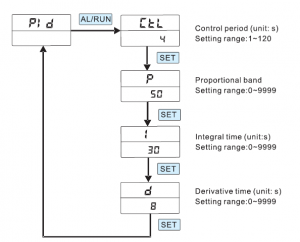
1) CU: Control period, sailing range 0-5-120 seconds (0=0-5sacond) , the controlling accuracy will be higher if set Ctl within 4 seconds when in SSR control output. andnormally set Ctl to 20 seoonds when in relay control output. The time ofCII can be shortened if there is not the satisfaction temperature controlling required. But based on the different heating system, the shorter control period will be accordingly shorten the working time of the mechanical switch.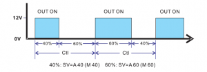
P: Proportional band, to accelerate the response speed and Improve the adjustment accuracy oft he system. The response speed and adjustment accuracy of the system will beimproved by increasing P, but this m11y easily bring Iha overshooting and even the instability to the system. The too small value of P will reduce lhe accuracy, slow the response speed,delay the adjustment time and even break the static and dynamic performance of the system. 2) I: Integration time. to eliminate the steady-state errors of the system. The larger I value,the faster the steady-state errors can be eliminated, but too large I value will cause the integral saturation phenomena at initial stage of response process. If I value is loo small, it will be h11rd to eliminate the steady-state errors of the system and ii will also 11ffect the adjustmi:int accuracy of the system. 3) D: Derivative time, to improve the dynamic performance of the system, and its main function is lo restrain deviation’s change in response process. and forec<1stthe devi<1tion change. But too large D value will advance the braking in response process, delay theadjustment time and will even degrade the anti-Interference performance oft he system.
5.6 Unit Parameters Setting
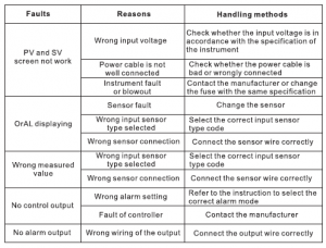
6. Common Faults and Handllng Methods
7. Warranty and service7 .1 Technlcal Assistance
 7. Warranty and service7 .1 Technlcal Assistance
If you have any problems installing or using this thermostat. please carefully and thoroughly review the instruction manual. If you require assistance, please write us to @lnk•blrd.com .We will reply your emails in 24 hours from Monday through Saturday. You can also visit our web site www.lnk•blrd.com to find the answers of the common technical question&.
7 .2 Warranty
INKBIRD TECH_ C_L_ warrants this thermostat for one year from Iha data of purchase when operated umter normal condition by the original purchaser (not transferable), againstdefects caused by INKBIRD’s workmanship or materials. This warranty Is limited to the repair or replacement, at INKBIRD’s discretion, of all or part of the thermostat. The originalreceipt is required for warranty purposes_ INKBIRD is not responsible for injury property damage or other consequential damages or damages of third parties arising dlrectly from an actual or alleged In mater of workmanship of the product. There are no representations, warranties, or conditions, express or implied, statutory or otherwise, other than herein contained in the sale of goods act or any other statue.
Read More About This Manual & Download PDF:
[xyz-ips snippet=”download-snippet”]