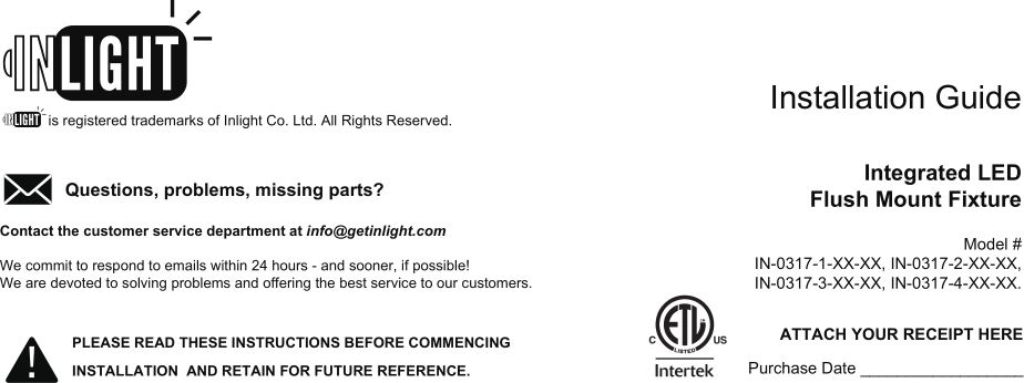
INLIGHT Integrated LED Flush Mount Fixture
Installation Guide
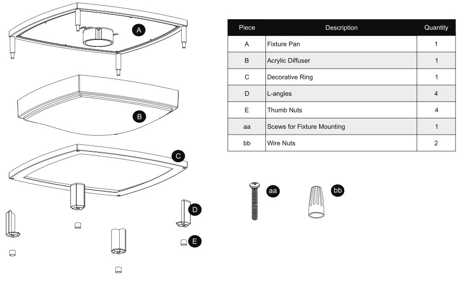
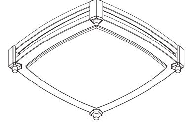
Package Contents
 Warranty
 Warranty
5-YEAR LIMITED WARRANTYThe manufacturer warrants this product to be free from defects in materials and workmanship for a period of five (5) years from date of purchase. This warranty applies only to the original consumer purchaser and only to products used in normal use and service. If this products is found to be defective, the manufacturer’s only obligation, and your exclusive remedy, is the repair or replacement of the product at he manufacturer’s discretion, provided that the product has not been damaged through misuse, abuse, accident, modifications, alterations, neglect, or mishandling. This warranty shall not apply to any product that is found to have been improperly installed, set-up, or used in any way not in accordance with the instructions supplied with the product. This warranty shall not apply to a failure of the product as a result an accident, misuse, abuse, negligence, alteration, or faulty installation, or any other failure not relating to faulty material workmanship. The manufacturer specifically disclaims any liability and shall not be liable for any consequential or incidental loss or damage, including labor/expense costs involved in the replacement or repair of said product.
Contact the Customer Service Team at [email protected] or visit www.getinlight.com
Safety Information
- To reduce the risk of death, personal injury or property damage from fire, electric shock, falling parts, cuts/abrasions, and other hazards read all warnings and instructions included with and on the the fixture box and all fixture labels.
- Before installing, servicing, or performing routine maintenance upon this equipment, follow these general precautions.
- Commercial installation, service and maintenance of luminaires should be performed by a qualified licensed electrician.
- For Residental installation: If you are unsure about the installation or maintenance of the luminaires, consult a qualified licensed electrician and check your local electrical code.
- DO NOT INSTALL DAMAGED PRODUCT!
- This fixture is intended to be connected to a properly installed and grounded UL listed junction box.
- These instructions do not purport to cover all details or variations in equipment nor to provide every possible contingency to meet in connection with installation, operation, or maintenance. Should further information be desired or should particular problems arise which are not covered sufficiently for the purchaser’s or owner’s purpose, this matter should be referred to Inlight Co. Ltd.
IMPORTANT SAFETY INSTRUCTIONS
WARNING: RISK OF ELECTRICALSHOCK
- Turn off electrical power at fuse or circuit breaker box before wiring fixture to the power supply.
- Turn off the power when you perform any maintenance. Verify that supply voltage is correct by comparing it with the luminaire label information.
- Make all electrical and grounded connections in accordance with the National Electrical Code and any applicable local code requirements.
- All wiring connections should be capped with UL approved wire connectors.
CAUTION: RISK OF INJURY
- Wear gloves and safety glasses at all times when removing luminaire from carton, installing, servicing or performing maintenance.
- Avoid direct eye exposure to the light source while it is on.
- Account for small parts and destroy packing material, as these may be hazardous to children.
WARNING: RISK OF BURN
- Allow fixture to cool before handling. Do not touch enclosure or light source.
- Do not exceed maximum wattage marked on luminaire label.
- Follow all lamp manufacturer’s warnings, recommendations and restrictions for: driver type, burning position, mounting locations/methods, replacement, and recycling.
CAUTION: RISK OF FIRE
- Keep combustible and other materials that can burn away from luminaire and lamp/lens.
Pre-Installation
PLANNING INSTALLATION
Compare all parts with the parts listed in the package contents section. If any part appears missing or damaged, do not install and use this light. Contact customer service.
***CONSULT A LOCAL LICENSED ELECTRICIAN OR ELECTRICAL CONTRACTOR IF YOU ARE NOT SURE ABOUT THE INSTALLATION.***
TOOLS REQUIRED
- Phillips Screwdriver
- Wire Cutter
- Ladder
- Wire Stripper
- Safety Goggles
Note: Safely dispose of packaging materials. Assistance will be required to support fixture during installation.
DIMMABLE FUNCTIONALITY
This fixture is dimmable with most regular dimmers. Following dimmers tested to be compatible with this fixture, dimming range up to: 10%-100%. If you are unfamiliar with electrical installations, it is recommended you have a qualified electrician do your installation.
SECTION A: PREPARING FOR INSTALLATION
1. Mounting Location
- Plan the layout of the fixtures and ensure power wiring is routed to all installation locations.
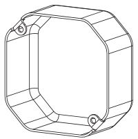
- A 3″ or 4″ junction box must be installed at each desired location before installing the fixture.
Junction Box (Not included)· 3″ & 4″ square or octagon· At least 1/2″ deep
2. Disconnect Power
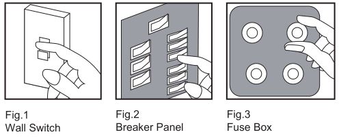
- Place the wall switch to the “OFF” position. (Fig.1.)
- Depending on which type of fuse box you have in your home:
Fig.2. Place either the main (Master) switch to the “OFF” position, cutting off power to your entire home OR turn off the individual switch that provides power to where the fixture will be installedORFig.3. Place either the main (Master) switch to the “OFF” position, cutting off power to your entire home OR turn off the fuse that provides power to where the fixture will be installed
- Carefully unpack the fixture. Lay out all parts on a clean surface.
- Remove the old fixture.
SECTION B: MOUNTING INSTALLATION
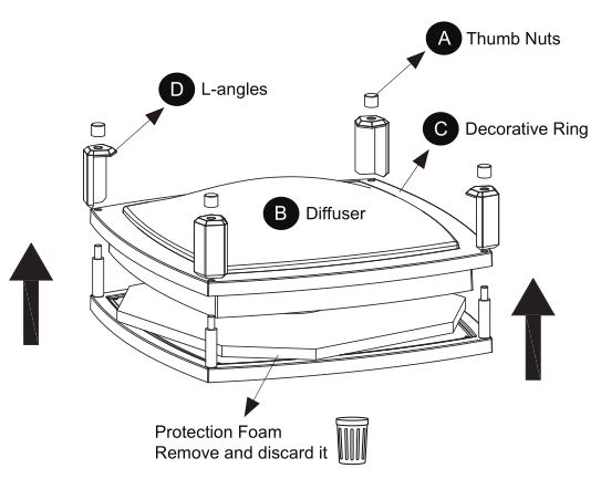
1. Unscrew the four thumb nuts from fixture– Twist counterclockwise to loosen the thumb nuts– Remove the thumb nuts from fixture.
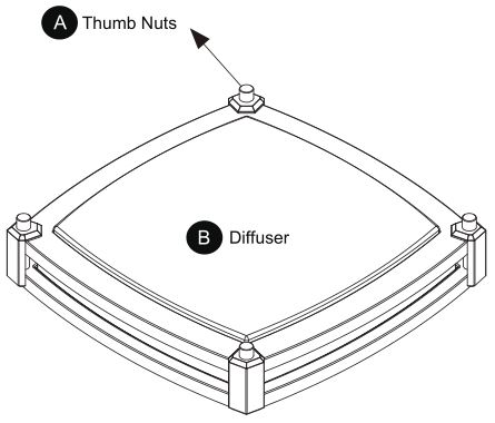
2. Disassemble the fixture
– Remove the decorative ring, L-angles and diffuser.– Remove the protection foam and discard it. Do not remove any other parts.
Note: To avoid damaging this product, place the components on a soft, non-abrasive surface such as carpet or cardboard.

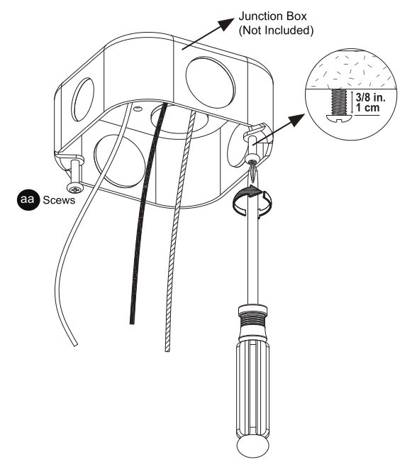
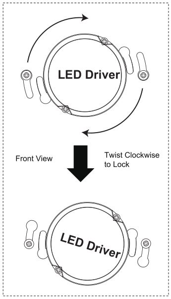
3. Install the hardware
- Use either the existing junction box screws or the mounting screws (aa) included in the hardware kit.
- Drive the screws into the junction box until there is abount 3/8 inch between the ceiling and the under side of the screw head.
Note: This fixture does not use a mounting breaket to secure it to the junction box.
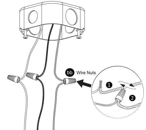
 5. Connect the wires
- Pull the power supply wires out from the junction box, strip 3/8″ of bare power supply wires.
- Hold two wires of the same color(one from the fixture, one from the junction box) next to each other and make sure the two stripped ends sit tightly against each other to guarantee effective connection later (but do not twist wires), See 1 .
Note: Ensure that no bare wires are exposed after making the connections.
- Push wires firmly into wire nut (bb). Use your fingers, twist wire nut clockwise until tight. Check for tightness by pulling wires, See 2 .
- Ensure the connectors are spliced tightly and carefully push the spliced wires back into the junction box.
Ground Wire:
- For safety and proper operation, the fixture must be properly grounded.(If house wiring does not include a ground wire, consult your local electrical code for approved grounding methods).
- A green or bare copper ground wire is pre-attached to the fixture. The fixture ground wire must be spliced to the green or bare copper ground wire in the junction box using one of the wire nuts (bb).
Power Wires:
- Connect the NEUTRAL supply wire (White) from the junction box to the NEUTRAL fixture wire (White)
- Connect the HOT supply wire (Black) from the junction box to the HOT fixture wire (Black)
6. Install the fixture
- Locate the keyhole slots on the fixture pan.
- Align the wider end of keyhole slots on the fixture pan with screw heads on the mounting plate, push fixture pan towards the mounting plate until screw heads go through the key hole slots.
- Once both screw heads have passed through the keyholes, twist the fixture pan, until both screws are situated at the narrow end of the keyhole slots.
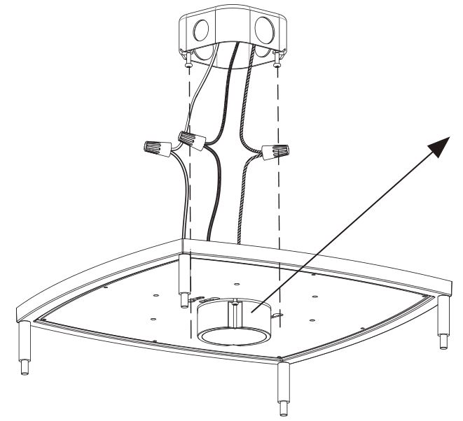
Note: 4-inch keyhole slots location illustrated.
Note: 16-inch or 18-inch fixture do not has the 3-inch keyhole slots.
7. Rotate the fixture pan– Rotate the fixture pan to a desired angle to match the layout of the room.
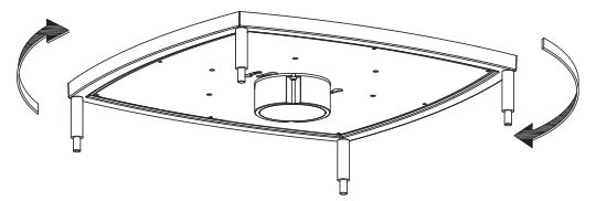
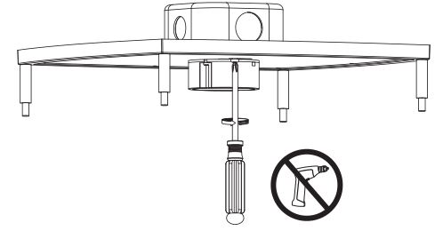
8. Secure the fixture– Hold fixture pan in place and tighten the screws (aa) just enough without distorting or damaging the fixture.
Note: Do not use power tools to install the screws, and do not overtighten the screws! Overtightening the screws may cause the fixture to warp and thus make assemble the fixture difficult.
 9. Assemble the fixture
- Seat the diffuser in the decorative ring.
- Place the diffuser and decorative ring against the fixture pan mounted on the ceiling. The threaded end of each thumb will need to pass through the holes in the ring for the ring to be installed.
- Once in place, hold both the diffuser and the ring in place, attach the L-angles, then the thumb nuts to secure the decorative ring.
Note: Assistance will be required to support the diffuser during installation.
10. Rotate the fixture to the desired angle
– Turn on power at circuit breaker or fuse box.– Turn the light switch on to activate the fixture.
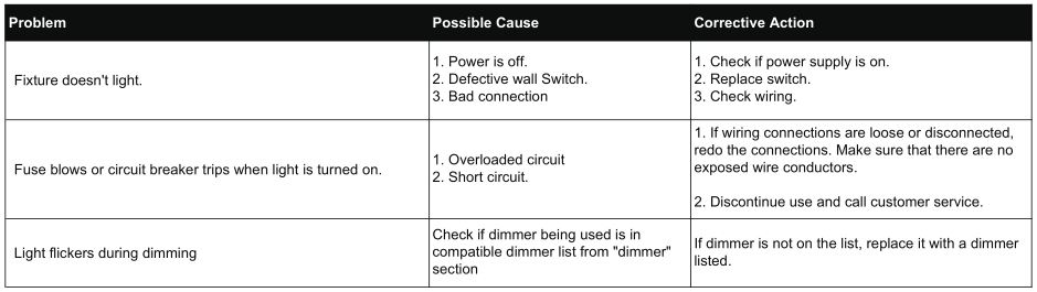
SECTION C: TROUBLESHOOTING
![]()
Questions, problems, missing parts? Before returning to the store, contact Inlight Customer Service[email protected]Retain this manual for future use.![]() is a trademark of Inlight Co. Ltd.
is a trademark of Inlight Co. Ltd.
References
[xyz-ips snippet=”download-snippet”]