![]()
EE1261 EchoStream® Four-ElementMotion DetectorInstallation Instructions
Overview
The EE1261 is a wireless motion detector that features a detection range of 15 meters, fixed or variable sleep time, a walk test feature, a front and reartamper switch, and increased immunity to radio frequency interference, vibration, static, lighting ambient temperature changes, and other causes of false activation. The EE1261 is designed with pet immunity up to 15kg weight and 30cm height.Caution: The EE1261 needs one minute for stabilization after power-up.During the stabilization period, the LED will blink twice per second, and the EE1261 will not be operational.Caution: Prior to operation, the EE1261 must be acclimated to the temperature of the install environment for a period of 60 minutes.
Inovonics Wireless Contact Information
If you have any problems with this procedure, contact Inovonics Wireless technical services:
- E-mail: [email protected].
- Phone: (800) 782-2709; (303) 939-9336.
EE1261 Components
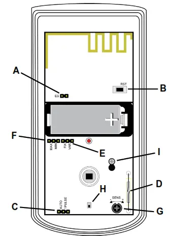
Figure 1 EE1261 components
A. EchoStream Select pinsB. Reset buttonC. Pulse count selection pinsD. Test mode reed switchE. Sleep time selection pinsF. Sleep duration selection pinsG. Sensitivity adjustment dialH. Case tamper switchI. Printed circuit board (PCB) mounting screw
What’s In The Carton
- Three wall mount screws.
- Three wall mount anchors.
- One selection jumper.
- One 3.0V lithium battery.
Installation and Startup
Installation Notes
- These products are designed to be installed and maintained by professional security technicians.
- Products are intended for indoor use.
- Manually test all products weekly.
Install/Replace Battery
To install the battery:
- Release the housing screw and raise the cover.
 Figure 2 Open the cover
 - Install the battery.
- Press the reset button.
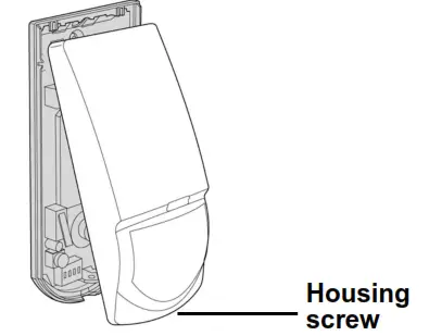 Figure 2 Open the cover
Enable EchoStream Select
To meet ETSI requirements, Inovonics has developed a new line of EE 868MHz-only products. These new 868MHz-only products are compatible with older systems that include EchoStream Select (ES) products. If you are not using any ES products in your current system, skip to section 2.4, “Select Automatic/Pulse Count”; if you are using any ES products in your current system, you will need to enable EchoStream Select compatibility on this new 868MHz-only product.To enable EchoStream Select compatibility:4. Place a selection jumper on the ES selection pins.Note: The selection jumper is included in the EE1261 hardware packet.5. Press the reset button.
Select Automatic/Pulse Count
The pulse count jumper setting provides a control for normal or difficult operating environments. An automatic pulse count is recommended for reliable operation in environments subject to temperature fluctuations that may cause false alarms. The single pulse count mode is more sensitive to minor temperature variations and should be used in sites where variant heat sources will not cause false alarms. The EE1261 is configured for a single pulse count by default. If you are planning to use the EE1261 in single pulse count, skip to section 2.5, “Select Fixed/Variable Sleep Time”; if you are planning to use the EE1261 in automatic pulse count, you will need to configure it.To configure the EE1261 for automatic pulse count:6. Move the selection jumper on the pulse count selection pins to the left two pins, marked AUTO, to select automatic pulse count.7. Press the reset button.
Select Fixed/Variable Sleep Time
When set to variable, if the EE1261 senses motion, it will transmit an alarm, then enter sleep mode for the sleep time duration; if motion is sensed before the sleep time duration has expired, the EE1261 will restart the sleep time duration. Variable sleep time is the recommended, default setting for high-traffic commercial environments.When set to fixed, if the EE1261 senses motion, it will transmit an alarm, then enter sleep mode until the sleep time duration expires; if motion is sensed when the sleep time duration has expired, the EE1261 will transmit another alarm. Fixed sleep time is only recommended for low-traffic, residential operating environments.The EE1261 is configured for variable sleep time by default. If you are planning to use the EE1261 in variable sleep time, skip to section 2.6, “Select Sleep Duration”; if you are planning to use the EE1261 in fixed sleep time, you will need to configure it. To configure the EE1261 for fixed sleep time:8. Move the selection jumper on the sleep time selection pins to the left two pins, marked FIX, to select fixed sleep time.9. Press the reset button.
Select Sleep Duration
If the sleep duration is set to maximum, the sleep duration will be 180 seconds. Maximum is the recommended, default setting for most environments.If the sleep duration is set to a minimum and the sleep time is set to fix, the EE1261 will have a sleep time of 15 seconds for the first six transmissions while motion is still sensed, followed by one extended sleep period of 180 seconds. If the sleep duration is set to a minimum and the sleep time is set to variable, the EE1261 will have a sleep time of 15 seconds.Caution: EE1261 motion detectors set in the minimum mode will have a decreased battery life.The EE1261 is configured for maximum sleep duration by default. If you are planning to use the EE1261 set for maximum sleep duration, skip to section 2.7, “Using Sleep Time and Sleep Duration”; if you are planning to use the EE1261 set for minimum sleep duration, you will need to configure it.To configure the EE1261 for minimum sleep duration:10. Move the selection jumper on sleep duration selection pins to the right two pins, marked MIN, to select a minimum sleep duration.11. Press the reset button.
Using Sleep Time and Sleep Duration
Maximizing battery lifeTo prolong the battery life of the EE1261, select MAX on the sleep duration pins, and VAR on the sleep time selection pins. With the variable sleep timer active and the sleep duration set to maximum, the detector first sends an alarm and then sleeps for 180 seconds. If the detector sees movement during this time, it restarts the sleep timer and doesn’t send an alarm. This mode is recommended for high-traffic environments with frequent activity during disarmed periods.Increasing catch rate (and UK DD243 installations)To maintain optimum detection immediately following system arming, select MIN on the sleep duration pins, and FIX on the sleep time selection pins.When the detector sees motion it goes to sleep for 15 seconds. If the detector sees movement during this time and is still active, it sends a new activation at the end of the 15-second window. The detector continues to do this for five more cycles. After six consecutive cycles, the detector goes to sleep for an extended 180 second period to conserve batteries. This mode may be used for DD243 installations in the UK. Battery life may be significantly shortened by use of this setting.
Adjust sensitivity
The sensitivity of the motion detector can be adjusted to fit your specific application, as needed. To adjust sensitivity:12. Use a Phillips head screwdriver to turn the sensitivity adjustment dial.
- Turn the dial to the left, towards the minus sign, to decrease the motion detector’s sensitivity.
- Turn the dial to the right, towards the plus sign, to increase the motion detector’s sensitivity.
Note: Only the mid to high setting of the sensitivity adjustment dial is EN 50131-2-2 compliant.13. Press the reset button.
Register the Transmitter
The EE1261 must be registered with the system receiver in order to bemonitored and supervised. Each EE1261 has a unique factory-programmed identification number. Refer to the receiver, network coordinator, or control panel installation instructions for details on registering a transmitter.14. When prompted, press the reset button.Caution: The EE1261 should be tested after registration to ensure operation. To test the EE1261, activate each of the conditions and ensure an appropriate response.Caution: When pressing the reset button, make sure you don’t also touch the EchoStream Select pins. Touching the EchoStream Select pins while pressing the reset button can inadvertently set the EE1261 to the wrong frequency band.Note: The EE1261 retains programming data in non-volatile memory. It does not require re-programming after the loss of power.
Mount the Transmitter
Mount the transmitter.15. Loosen the pcb mounting screw enough to slide the board back over the keyhole slot.16. Lift and remove the EE1261 pcb from the housing.17. Use the included hardware to mount the EE1261 housing backplate to the mounting surface.
- If using the wall tamper function for increased security, mount the housing backplate per Figure 3, ensuring the tamper switch is depressed.
Figure 3 EE1261 mounting backplate• If not using the wall tamper, mount the housing backplate using all appropriate hardware.18. Replace the PCB and slide it into position so that the PCB mounting screw is holding the board in place.19. Tighten the PCB mounting screw.20. Replace the EE1261 cover.21. Replace the housing screw.
Optional Brackets
Optional wall and ceiling mount brackets, Inovonics part number ACC665, are available. The wall and ceiling mount brackets must not be used for graded applications.
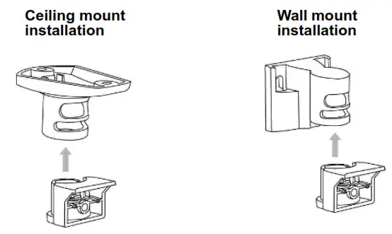
Figure 4 Ceiling and wall mount brackets To mount a ceiling or wall bracket:
- Loosen the pcb mounting screw enough to slide the board back over the keyhole slot.
- Lift and remove the EE1261 pcb from the housing.
- Attach the housing to the bracket.
- Replace the pcb and slide it into position so that the pcb mounting screw is holding the board in place.
- Tighten the pcb mounting screw.Note: Any obstruction to the detector’s field of view will degrade its performance and reliability. Make sure the detector is mounted with a clear line of sight.

Test the EE1261
Caution: The EE1261 should be tested after registration to ensure operation. To test the EE1261, activate each of the conditions and ensure an appropriate response.
Perform a Walk Test
The walk test is performed to ensure motion is sensed and an RF transmission results. To perform a walk test:
- Swipe the magnet past the reed switch. The five-minute walk test will begin; every time motion is sensed, the LED will light and the EE1261 will transmit a signal.
- Walk-in front of the motion detector to test the sensor.
- After five minutes the walk test will automatically end.Note: The EE1261 will remain in a tamper condition during the walk test.
Operation
The EE1261 transmitter signals an alarm condition when motion is detected by the sensor.
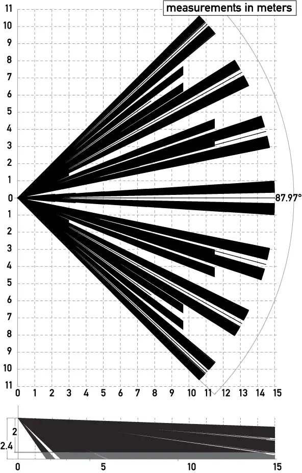
Figure 6 Standard mounting height and range
Specifications
Dimensions: 11.4 cm x 6.4 cm x 4.1 cm (4.5”H x 2.5”Wx 1.6”D).Detection method: Quad element PIR.Storage temperature: -20° to 60°C (-4° to 140°F).Operating temperature: -10° to 50°C (14° to 122°F).Humidity: 0 – 90% (non-condensing).Battery: 3V LiMnO2, BAT604 (Panasonic CR123A or Duracell DL123A).Temperature compensation: Yes.Tamper: Housing and wall tamper.PIR RF interference immunity: Greater than 30 v/m 26 MHz – 1 GHz.Stabilization period: One minute.Alarm lockout time: Three minutes (in fixed, maximum mode).Walk test period: Five minutes.Quiescent current consumption: 11.25 µA.Maximum current: 20.5 mA.Voltage: 3.0 VDC.Mounting height: 2.1 to 2.7 m (7 to 9 feet).Output power: 13mW.Firmware revision: 90526, v1.2.Countries in which Inovonics European products can be distributed: Belgium, Bulgaria, Croatia, Cyprus, Czech Republic, Denmark, Estonia, Finland, France, Greece, Hungary, Ireland, Italy, Latvia, Lithuania, Luxembourg, Malta, Netherlands, Norway, Poland, Portugal, Romania, Slovakia, Slovenia, Spain, Sweden, United Kingdom.Note: Specifications and data are subject to change without notice.Note: Inovonics supports recycling and reuse whenever possible. Please recycle these parts using a certified electronics recycler.Caution: Changes or modifications to this unit not expressly approved by Inovonics may void the installer’s authority to operate the equipment as well as the product warranty.
Simplified Declaration of Conformity
 report this ad
Hereby, Inovonics declares that the radio equipment type EE1261 is in compliance with Directive 2014/53/EU.The full text of the EU declaration of conformity is available at the following Internet address: www.inovonics.com.
References
[xyz-ips snippet=”download-snippet”]