
insportine 20216 Fitness stepmill inSPORTline ProfiStair

SAFETY INSTRUCTIONS
- Read this manual carefully before first use and retain it for future reference.
- Use the product only according to this manual and for its intended purpose. Do not modify the product in any way.
- WARNING! Before maintenance, always unplug the device from electrical outlet to prevent burning or electrocuting yourself.
- While the product is turned on, pay attention to its operating status to avoid an injury. If the machine is idle, it is recommended to turn off the power and unplug the power cord.
- Keep the stepmill away from children and pets. Never leave them unattended near the device.
- Never use the product if parts of it are worn or damaged. Regularly check all the screws, nuts and other connecting parts to make sure they are not loose. Damaged or worn parts should be replaced immediately.
- Never use the stepmill if the plug or power cord are damaged. If the power cord doesn’t work properly or if it has been exposed to water, stop using it at once and have it repaired or replaced by a qualified technician or the customer service.
- Never use the power cord or other cables to move the device.
- Make sure the power cord never comes into contact with a heated surface. Keep it in a sufficient distance from heated surfaces or objects.
- If the ventilation ducts are clogged with hair or dust, make sure you clean them before operating the stepmill.
- Never insert anything into the open spaces found on the device.
- This product cannot be used outdoors.
- Do not use the product in a room without proper ventilation or with low levels of oxygen.
- Always unplug the power cord after shutting the stepmill off.
- Make sure the device is plugged into a properly grounded socket.
- This product is not intended for people with physical or mental disabilities and unexperienced users (including children), unless they are under qualified supervision.
- Exercise according to the given instructions. Improper exercising may result in an injury. Make sure not to exceed your limits.
- For the assembly, prepare a wide area with a flat and clean surface.
- The stepmill can only be placed on a flat, clean and solid surface. Keep a safety clearance of 2 x 1 m behind the device and at least 0.6 m around the rest.
- You should provide regular maintenance and check the stepmill for damage.
- No adjustable part should protrude and limit the user’s movements.
- If the first stair is too high for you, use the foot supports to get on.
- Always hold on to the handlebars while getting on/off the device.
- Wear appropriate sports clothes and shoes. Avoid loose clothes so they don’t get stuck in the moving parts of the stepmill.
- Make sure you attach the safety clip to your clothes. Step onto the second stair while holding on to the handle bars and use this as a standby position. Don’t start exercising before you stand on the stair.
- Always hold the handlebar as a support.
- Press the STOP key to finish exercising and wait until the stairs stop completely. Only then step off the stepmill.
- Max. user weight: 160 kg
- Category: S (according to EN957) suitable for commercial and professional use
- WARNING! The heart rate frequency monitoring may not be completely accurate. Overexertion during training can lead to a serious injury or even death. If you start to feel faint, stop the exercise immediately.
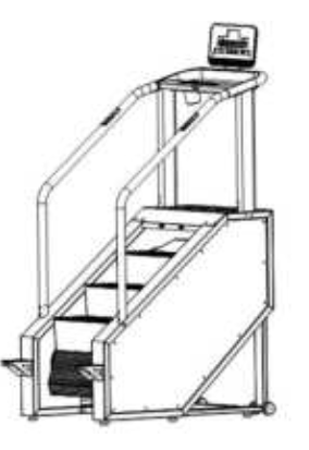
PRODUCT DESCRIPTION

- Console
- Safety key
- Posts
- Handlebars
- Stairs
- Pedals
- Transport wheels
- Display
SPECIFICATIONS
| Weight limit | 160 kg |
| Dimensions | 1464 x 810 x 2555 |
| Stairs dimensions | 550 x 240 x 180 |
| Speed | 1–10 levels (14-140 steps / min) |
| Number of steps | 3 |
The company reserves the right to change specifications.
ASSEMBLY
The package contains these parts. Unfold all parts on a clean, flat surface and check that no parts are missing.
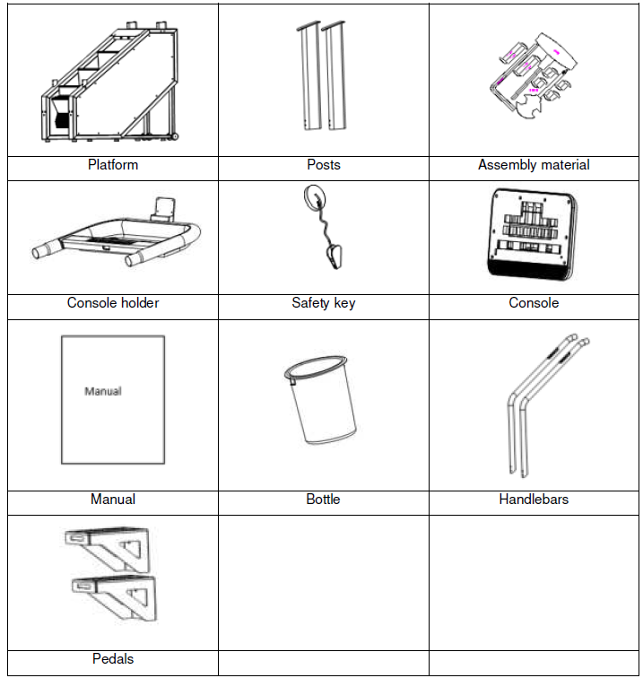
ASSEMBLY MATERIAL

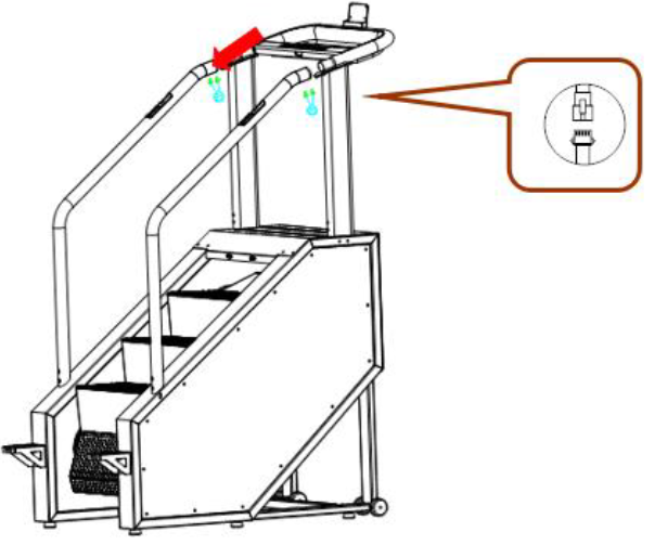
STEP 1: Fasten the pedals with 6 M8x15 screws.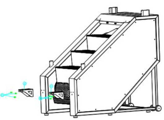
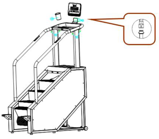
STEP 2: Connect the communication cables and fasten the posts with 8 M8x15 screws, but do not tighten the screws yet.
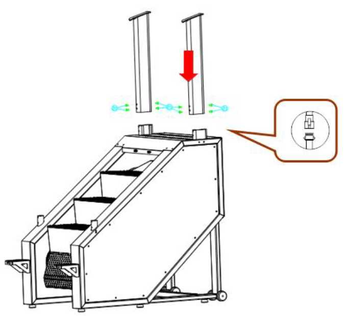
STEP 3: Fasten the handles with 4 M8x15 screws and 4 curved washers, but do not tighten the screws yet.

STEP 4: Connect the console and handles. Connect the cables and fasten with 4 M8x15 screws. Do not tighten the screws yet.
STEP 5: Attach the console bracket with 4 M8x15 screws, connect the communication cables from the console, and secure the console with the ST4x16 screws.
STEP 6: Tighten all screws.
WARM UP
This stage helps get the blood flowing around the body and the muscles working properly. It will also reduce the risk of cramp and muscle injury. It is advisable to do a few stretching exercises as shown below. Each stretch should be held for approximately 30 seconds, do not force or jerk your muscles into a stretch. If it hurts, STOP.
- Touching your toesSlowly bend your back from hips. Keep your back and arms relaxed while stretching downwards to your toes. Do it as far as you are able and hold the position for 15 seconds. Bend your knees slightly.
- Upper thighsWith one hand, lean against the wall. Put one hand down behind you and grasp the foot. Pull the leg as far as you can. Hold for 30 seconds and repeat at the other leg.
- Hamstring stretchedSit and outstretch your right leg. Rest the sole of your left foot against the inside of your right tight. Stretch out your right arm along your right leg as far as you can. Hold for 15 seconds and relax. Repeat all with your left leg and left arm.
- Inside thighsSit on the floor with your toes together. The knees are facing out. Pull the feet to the groin. Push your knees down. Hold for 30-40 seconds, if possible.
- Calves and Achilles tendonLean against a wall with your left leg in front of the right one and your arms forward. Stretch out your right leg and keep your left foot on the floor. Bend your left leg and lean forwards by moving your right hip in the direction of the wall. Hold for 15 seconds. Keep your leg stretched and repeat exercising with other leg.
CONSOLE
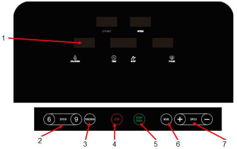
- Display
- Quick speed change
- Programs
- Stop
- Start
- Program change
- Speed + and –
CONSOLE DESCRIPTION
- P0 is user program, P1 – P36 are preset programs, 3 user programs, FAT program
- 0,56 inches display, 8 buttons
- Speed 1–10 (14–140 steps / min)
- Automatic status check, fault information
- MP3 player (depending on version)
- HRC function (depending on version)
- Bluetooth (depending on version)
DISPLAY
| SPEED | Display speed |
| PULSE | Display current heart rate |
| TIME/STEP | display time and number of steps |
| CALORIES | Display burned calories (only orientational) |
| STY HGT | Display height |
| PROG | Press button to choose program P1-P36, U01, U02, U03, FAT |
| MODE | In the manual program, use the button to toggle between counting calories, time, time in programs P01-P36 (default: 30 min) |
| START/STOP | Starts / stops the device |
| + | Increase speed, parameter change |
| – | Decrease speed, parameter change |
SAFETY KEY
The safety key serves as protection in the event of a failure or if the stairs must be switched off immediately. If there is no liner security key, E-07 and a beep are displayed. Each time you insert the security key, the display lights up for 2 seconds.
SAFETY INSTRUCTIONS
- Plug the machine into a 10A grounded outlet, then turn on the power switch. The console displays all functions and prompts for a security key.
- Insert the safety key and attach it to your clothes. Then the entire display lights up for 2 seconds. All counters will be reset.
- Use PROG button to choose program: P1-P36, U1, U2, U3, FAT.
- P0 is user program. Use MODE button to change values. Speed can be adjusted by user. Default value is 1 (14 steps/min)
- Training mode 1: calculates time and calories, cannot set values
- Training mode 2: countdown time, with + and – buttons you can adjust value 5 – 99. Default value is 30:00.
- Training mode 3: countdown calories, with + and – buttons you can adjust value 20 – 999 Cal, default value is 50 cal.
- P1-P36 are preset programs. You can set the training time with the + and – buttons and press the MODE button to restore the original value. Original value: 30:00, adjustable value from 5-99 min.
- After setting the program, press START. The countdown starts with 5 seconds, accompanied by a beep. Once the countdown reaches 1, the stairs begin to move slowly.
- During training, adjust the speed with the + and – buttons, or quickly selection buttons.
- Programs P1-P36 are divided into 10 segments, divided evenly over time. Change of speed is only for selected segment. 3 beeps before transition to the next the segment. Stairs will turn off when all segments are completed.
- In standby mode, press START to start the stairs.
- During operation, pressing STOP causes the motor to slow down slowly until it stops. All settings return to their original values.
- If you disconnect the Safety Key at any time, E-07 is displayed, accompanied by a beep. The stairs stop.
- BODY FAT TEST: Use the PROG button to select FAT, the CALORIES window displays the adjustable values. Use MODE to set the value, the PULSE window displays the parameter, and the + and – buttons to adjust the parameter.
- F1 (sex): 1 man, 2 woman, default value 1
- F2 (age): adjustable value: 1 – 99, default value: 25
- F3 (height): adjustable value: 100 – 200 cm, default value: 170 cm
- F4 (weight): adjustable value: 20 – 150 kg, default value: 70 kg
- F5 (BMI): indicates that all values are set, and the test is ready. Hold both sensors and wait 8 seconds to display the BMI.
| <18 | underweight |
| 18–24 | normal weight |
| 25–28 | overweight |
| 29> | obesity |
MP3 (If available)Stairs have a built-in dual-channel speaker, switch and no mute function. You can play music by connecting a 3.5 mm jack.The device includes a USB charging port and Bluetooth
HRC PROGRAM (If available)
- HRC1 limits speed to 6 level (84 steps / min)
- Use the PROG button to select the HRC program. Then use the MODE button to confirm the setting and move to the next setting. Use the + and – buttons to adjust the speed.o Age – adjustable value: 15-80, default value: 25o THR: (220 – age) *0,6o The target heart rate can be adjusted from 80 to 180o Time – adjustable value: 5-99 min, default value: 30 mino Speed changes depending on heart rateo Heart rate is detected every 30 seconds.o If the target heart rate is lower by 30 beats per minute then the target, the speed will increase by 28 steps / min.o If the target heart rate is lower by 6-29 beats per minute, the speed will increase by 14 steps / min.o If the target heart rate is higher by 30 beats per minute then the target, the speed will decrease by 28 steps / min.o If the target heart rate is higher by 6-29 beats per minute, the speed will decrease by 14 steps / min.o If the target heart rate is higher/lower by 0-5 beats / min, the speed will not change.
- If one of the following conditions occurs, the speed is reduced to a minimum for 20 seconds and then stops completely for another 15 seconds:o The heart rate is not detected twice in a rowo Heart rate exceeds limito The speed is too slow for a long time
- Speed is not controlled manually but automatically according to heart rate.
BLUETOOTHFor connection, refer to the application’s manual.
PROGRAMS
| Program | Level | 1 | 2 | 3 | 4 | 5 | 6 | 7 | 8 | 9 | 10 |
| P1 | SPEED | 1.0 | 3.0 | 4.0 | 4.0 | 4.0 | 5.0 | 5.0 | 2.0 | 3.0 | 2.0 |
| P2 | SPEED | 2.0 | 3.0 | 5.0 | 6.0 | 5.0 | 5.0 | 6.0 | 6.0 | 4.0 | 3.0 |
| P3 | SPEED | 2.0 | 3.0 | 6.0 | 6.0 | 5.0 | 5.0 | 5.0 | 6.0 | 4.0 | 3.0 |
| P4 | SPEED | 2.0 | 2.0 | 5.0 | 6.0 | 6.0 | 6.0 | 6.0 | 5.0 | 3.0 | 2.0 |
| P5 | SPEED | 3.0 | 4.0 | 6.0 | 5.0 | 4.0 | 4.0 | 5.0 | 5.0 | 4.0 | 3.0 |
| P6 | SPEED | 3.0 | 4.0 | 6.0 | 6.0 | 7.0 | 7.0 | 6.0 | 6.0 | 5.0 | 3.0 |
| P7 | SPEED | 3.0 | 4.0 | 4.0 | 3.0 | 4.0 | 3.0 | 4.0 | 4.0 | 3.0 | 2.0 |
| P8 | SPEED | 3.0 | 5.0 | 7.0 | 7.0 | 3.0 | 5.0 | 6.0 | 5.0 | 5.0 | 1.0 |
| P9 | SPEED | 3.0 | 3.0 | 3.0 | 4.0 | 5.0 | 6.0 | 5.0 | 4.0 | 5.0 | 1.0 |
| P10 | SPEED | 3.0 | 5.0 | 6.0 | 7.0 | 6.0 | 6.0 | 5.0 | 5.0 | 3.0 | 3.0 |
| P11 | SPEED | 4.0 | 5.0 | 3.0 | 3.0 | 6.0 | 7.0 | 7.0 | 6.0 | 6.0 | 1.0 |
| P12 | SPEED | 4.0 | 6.0 | 5.0 | 3.0 | 4.0 | 7.0 | 7.0 | 3.0 | 2.0 | 1.0 |
| P13 | SPEED | 2.0 | 4.0 | 6.0 | 6.0 | 6.0 | 7.0 | 7.0 | 6.0 | 4.0 | 3.0 |
| P14 | SPEED | 3.0 | 4.0 | 6.0 | 5.0 | 6.0 | 6.0 | 7.0 | 6.0 | 5.0 | 4.0 |
| P15 | SPEED | 3.0 | 4.0 | 8.0 | 8.0 | 6.0 | 6.0 | 6.0 | 4.0 | 5.0 | 4.0 |
| P16 | SPEED | 3.0 | 3.0 | 6.0 | 5.0 | 4.0 | 3.0 | 4.0 | 5.0 | 4.0 | 3.0 |
| P17 | SPEED | 4.0 | 5.0 | 6.0 | 7.0 | 6.0 | 5.0 | 4.0 | 3.0 | 2.0 | 2.0 |
| P18 | SPEED | 4.0 | 5.0 | 7.0 | 7.0 | 5.0 | 5.0 | 4.0 | 4.0 | 3.0 | 1.0 |
| P19 | SPEED | 4.0 | 5.0 | 5.0 | 4.0 | 5.0 | 6.0 | 5.0 | 4.0 | 3.0 | 3.0 |
| P20 | SPEED | 4.0 | 6.0 | 7.0 | 8.0 | 7.0 | 6.0 | 5.0 | 6.0 | 5.0 | 2.0 |
| P21 | SPEED | 4.0 | 4.0 | 7.0 | 7.0 | 5.0 | 5.0 | 6.0 | 5.0 | 4.0 | 3.0 |
| P22 | SPEED | 4.0 | 6.0 | 5.0 | 4.0 | 3.0 | 3.0 | 4.0 | 4.0 | 3.0 | 2.0 |
| P23 | SPEED | 5.0 | 6.0 | 6.0 | 6.0 | 7.0 | 7.0 | 7.0 | 8.0 | 7.0 | 4.0 |
| P24 | SPEED | 5.0 | 7.0 | 5.0 | 5.0 | 6.0 | 6.0 | 7.0 | 5.0 | 5.0 | 3.0 |
| P25 | SPEED | 3.0 | 5.0 | 7.0 | 6.0 | 5.0 | 6.0 | 6.0 | 5.0 | 5.0 | 2.0 |
| P26 | SPEED | 4.0 | 5.0 | 7.0 | 8.0 | 7.0 | 7.0 | 8.0 | 5.0 | 6.0 | 2.0 |
| P27 | SPEED | 4.0 | 5.0 | 4.0 | 5.0 | 6.0 | 7.0 | 6.0 | 5.0 | 6.0 | 3.0 |
| P28 | SPEED | 4.0 | 4.0 | 7.0 | 7.0 | 8.0 | 8.0 | 7.0 | 7.0 | 5.0 | 4.0 |
| P29 | SPEED | 5.0 | 6.0 | 8.0 | 8.0 | 7.0 | 6.0 | 5.0 | 6.0 | 6.0 | 5.0 |
| P30 | SPEED | 5.0 | 6.0 | 8.0 | 7.0 | 7.0 | 7.0 | 8.0 | 8.0 | 7.0 | 5.0 |
| P31 | SPEED | 5.0 | 6.0 | 6.0 | 7.0 | 6.0 | 8.0 | 6.0 | 8.0 | 5.0 | 4.0 |
| P32 | SPEED | 5.0 | 7.0 | 8.0 | 8.0 | 5.0 | 7.0 | 8.0 | 7.0 | 6.0 | 4.0 |
| P33 | SPEED | 5.0 | 8.0 | 8.0 | 7.0 | 9.0 | 8.0 | 7.0 | 6.0 | 5.0 | 3.0 |
| P34 | SPEED | 5.0 | 7.0 | 8.0 | 8.0 | 8.0 | 6.0 | 8.0 | 8.0 | 6.0 | 5.0 |
| P35 | SPEED | 6.0 | 7.0 | 7.0 | 8.0 | 8.0 | 8.0 | 8.0 | 7.0 | 8.0 | 4.0 |
| P36 | SPEED | 6.0 | 8.0 | 8.0 | 6.0 | 7.0 | 8.0 | 8.0 | 6.0 | 6.0 | 3.0 |
COMMON ERRORS AND SOLUTIONS
| Error
Sign |
/ | Cause | Solution | |||
|
The system is not working |
Not plugged in / Power switch is off | Plug in / switch on | ||||
| Safety key not connected | Reinsert the key | |||||
| Damaged transformer | Check / replace the transformer | |||||
| Short circuit | Check the wiring | |||||
| Sudden stop | Safety key is disconnected | Reinsert the key | ||||
| System exception | Contact service for repair | |||||
| The does work | button
not |
Damaged button |
Replace the button / replace the motherboard | |||
|
E-01 |
Communication cable error | Check wiring / replace if necessary | ||||
| Damaged console | Replace the console | |||||
| Damaged transformer | Replace the transformer | |||||
| Damaged control | Replace the control | |||||
| E-02 | Engine failure | Replace the engine | ||||
| Poor cable and motherboard communication | Check / reconnect cables | |||||
|
E-03 |
The photoelectric correctly | sensor | is | not | connected | Check the connection |
| Damaged photoelectric sensor | Replace the sensor | |||||
| Poor connection between photoelectric sensor and motherboard | Check the connection | |||||
| Motherboard damaged | Replace the motherboard | |||||
| E-05 | Damaged driver | Replace the driver | ||||
| Damaged engine | Replace the engine | |||||
|
E-07 |
The console does not detect the security key |
1. Check if the key is plugged in 2.Disconnect and reconnect the key
3. Replace the console |
||||
| The heart rate is not displayed | The sensors in the handles are not connected or the cables are damaged | Check the connection | ||||
| Console error | Replace the console | |||||
| The console is displaying data incorrectly | Loose display screws | Tighten the screws | ||||
| Console error | Replace the console |
TRANSPORTATION
Before moving, make sure that the machine is turned off and not connected to the electrical circuit. Then lift the stairs if they are too heavy, ask another person for help. Move the stairs on the transport wheels.![]()
CONENCTION

Use only a properly grounded 220-240 V outlet for connection.
USE
- Place the stairs on a flat and firm surface. Turn on the stairs and make sure they work.
- Attach the Safety Key and plug it into the console.
- Check the stability of the device before training. Never start the device unless the user is ready. Stand on the second step and grasp the handles. Then press START with one hand while holding the handles with the other. The stairs speed is lowered for 5 seconds to 1 level. Then the user can set the speed with +/- buttons.
- During exercise, you can also use the quick-change buttons to change the speed. (Speed can be increased by multiple levels, so be careful)
- Press STOP to stop the motor.
- Program selection:Turn on the stairs, after the console loads, press SELECT. Select the desired program and press START to start the program. You can change the speed using the +/- buttons. Press STOP to stop the stairs.
- Heart rate: After you start the stairs, grasp the sensors on the handles and the heart rate will appear after a few seconds.
WARNING! The heart rate frequency monitoring may not be completely accurate. Overexertion during training can lead to a serious injury or even death. If you start to feel faint, stop the exercise immediately.NOTE: If you disconnect the Safety Key, the machine will immediately shut down and a “—-” or “E07” error message will be displayed.
MAINTENANCE
Lubrication: After a long period of use, dirt and old grease may settle on the chain and gears. We recommend cleaning and lubricating the parts regularly.Clean the belt and pulley grooves regularly.
MECHANICAL PROBLEMS
| Error | Cause | Solution |
| The machine will not start | The device is not connected | Plug in |
| Safety key not connected | Insert the key into the console | |
| Short circuit | Check the motherboard and signal cables | |
| The switch is in the off position | Turn the power switch to the ON position | |
| Short circuit fuses | Replace the fuses | |
| Stairs do not move smoothly | Insufficient lubrication | Clean and lubricate again |
| The chain is too tight | Adjust the chain stiffness |
CONSOLE ERROR
| No. | Description | Solution |
| E1 | Bad communication
Communication between the motherboard and the console is faulty when turned on. |
3 beeps and error code is displayed.
Communication between motherboard and console is wrong. Check cable connections and replace cables if necessary. |
| E3 | Poor connection of motor cables | A beep sounds 9 times and an error code is displayed.
Check cable connections reconnect cables if necessary. Check for burnt odor. Check the system board. |
| No speed sensor signal
The engine speed is not recorded for 3 seconds |
A beep sounds 9 times and an error code is displayed. After 10 seconds, the console enters standby mode and can be restarted.
Check the connection of the speed sensor or the condition of the speed sensor. |
|
| E4 | Drive motor error | Check motor connection reconnect if necessary. Check the connection to the control board. Check the condition of the cables. |
| E5 | Overvoltage protection
The voltage is higher by 6 A for more than 3 seconds |
A beep sounds 9 times and an error code is displayed. After 10 seconds, the console enters standby mode and can be restarted.
The device is protected against high voltage or high load. Check for burnt odor. Check the status of the control board, motor and power supply. Replace in case of malfunction. |
| E6 | Damaged circuit | A beep sounds 9 times and an error code is displayed.
Check the voltage. Check the status of the control board and the correct connection of the motor to the control board.
|
ENVIRONMENT PROTECTIONAfter the product lifespan expired or if the possible repairing is uneconomic, dispose it according to the local laws and environmentally friendly in the nearest scrapyard.By proper disposal you will protect the environment and natural sources. Moreover, you can help protect human health. If you are not sure in correct disposing, ask local authorities to avoid law violation or sanctions.Don’t put the batteries among house waste but hand them in to the recycling place.
TERMS AND CONDITIONS OF WARRANTY, WARRANTY CLAIMSGeneral Conditions of Warranty and Definition of TermsAll Warranty Conditions stated here under determine Warranty Coverage and Warranty Claim Procedure. Conditions of Warranty and Warranty Claims are governed by Act No. 89/2012 Coll. Civil
Code, and Act No. 634/1992 Coll., Consumer Protection, as amended, also in cases that are not specified by these Warranty rules.The seller is SEVEN SPORT s.r.o. with its registered office in Strakonická street 1151/2c, Prague 150 00, Company Registration Number: 26847264, registered in the Trade Register at Regional Court in Prague, Section C, Insert No. 116888.According to valid legal regulations it depends whether the Buyer is the End Customer or not.
“The Buyer who is the End Customer” or simply the “End Customer” is the legal entity that does not conclude and execute the Contract in order to run or promote his own trade or business activities. “The Buyer who is not the End Customer” is a Businessman that buys Goods or uses services for the purpose of using the Goods or services for his own business activities. The Buyer conforms to the General Purchase Agreement and business conditions.These Conditions of Warranty and Warranty Claims are an integral part of every Purchase Agreement made between the Seller and the Buyer. All Warranty Conditions are valid and binding, unless otherwise specified in the Purchase Agreement, in the Amendment to this Contract or in another written agreement.
Warranty ConditionsWarranty PeriodThe Seller provides the Buyer a 24 months Warranty for Goods Quality, unless otherwise specified in the Certificate of Warranty, Invoice, Bill of Delivery or other documents related to the Goods. The legal warranty period provided to the Consumer is not affected.By the Warranty for Goods Quality, the Seller guarantees that the delivered Goods shall be, for a certain period of time, suitable for regular or contracted use, and that the Goods shall maintain its regular or contracted features.
The Warranty does not cover defects resulting from (if applicable):
- User’s fault, i.e. product damage caused by unqualified repair work, improper assembly, insufficient insertion of seat post into frame, insufficient tightening of pedals and cranks
- Improper maintenance
- Mechanical damages
- Regular use (e.g. wearing out of rubber and plastic parts, moving mechanisms, joints, wear of brake pads/blocks, chain, tires, cassette/multi wheel etc.)
- Unavoidable event, natural disaster
- Adjustments made by unqualified person
- Improper maintenance, improper placement, damages caused by low or high temperature, water, inappropriate pressure, shocks, intentional changes in design or construction etc.
Warranty Claim Procedure
The Buyer is obliged to check the Goods delivered by the Seller immediately after taking the responsibility for the Goods and its damages, i.e. immediately after its delivery. The Buyer must check the Goods so that he discovers all the defects that can be discovered by such check.
When making a Warranty Claim the Buyer is obliged, on request of the Seller, to prove the purchase and validity of the claim by the Invoice or Bill of Delivery that includes the product’s serial number, or eventually by the documents without the serial number. If the Buyer does not prove the validity of the Warranty Claim by these documents, the Seller has the right to reject the Warranty Claim.
If the Buyer gives notice of a defect that is not covered by the Warranty (e.g. in the case that the Warranty Conditions were not fulfilled or in the case of reporting the defect by mistake etc.), the Seller is eligible to require a compensation for all the costs arising from the repair. The cost shall be calculated according to the valid price list of services and transport costs.If the Seller finds out (by testing) that the product is not damaged, the Warranty Claim is not accepted. The Seller reserves the right to claim a compensation for costs arising from the false Warranty Claim.
In case the Buyer makes a claim about the Goods that is legally covered by the Warranty provided by the Seller, the Seller shall fix the reported defects by means of repair or by the exchange of the damaged part or product for a new one. Based on the agreement of the Buyer, the Seller has the right to exchange the defected Goods for a fully compatible Goods of the same or better technical characteristics. The Seller is entitled to choose the form of the Warranty Claim Procedures described in this paragraph.
The Seller shall settle the Warranty Claim within 30 days after the delivery of the defective Goods, unless a longer period has been agreed upon. The day when the repaired or exchanged Goods is handed over to the Buyer is considered to be the day of the Warranty Claim settlement. When the Seller is not able to settle the Warranty Claim within the agreed period due to the specific nature of the Goods defect, he and the Buyer shall make an agreement about an alternative solution. In case such agreement is not made, the Seller is obliged to provide the Buyer with a financial compensation in the form of a refund.
![]()
References
[xyz-ips snippet=”download-snippet”]