![]()
 Tš-L (Version 2)OscillatorUser Manual
Description
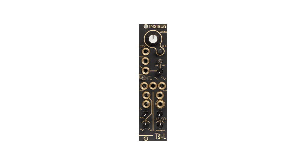
The Instruō Tš-L is a fully analogue voltage-controlled oscillator with a plethora of features in a very small footprint.Its triangle core circuitry allows for extremely consistent waveforms over a wide frequency range. The triangle foundation is used to generate its sine waveform which holds consistent shape and amplitude across Tš-L’s wide range. The outputs consist of simultaneous Square/Sub, Triangle, and Sine waveforms, with an additional voltage controllable wavefolder and a complex PWM waveshaper.Tš-L includes every feature needed to powerfully perform as a rich, ultra-compact audio source, as well as functioning equally as a versatile modulation source.
Features
- 1V/Oct tracking
- Linear and exponential frequency modulation
- Pulse width modulation
- Wavefolding
- Soft synchronisation
- Sub-square mode
- LFO range at the push of a button
Installation
- Confirm that the Eurorack synthesizer system is powered off.
- Locate 6 HP of space in your Eurorack synthesizer case.
- Connect the 10 pin side of the IDC power cable to the 2×5 pin header on the back of the module, confirming that the red stripe on the power cable is connected to -12V.
- Connect the 16 pin side of the IDC power cable to the 2×8 pin header on your Eurorack power supply, confirming that the red stripe on the power cable is connected to -12V.
- Mount the Instruō Tš-L in your Eurorack synthesizer case.
- Power your Eurorack synthesizer system on.
Note:This module has reverse polarity protection.Inverted installation of the power cable will not damage the module.
Specifications
- Width: 6 HP
- Depth: 35mm
- +12V: 60mA
- -12V: 40mA
Tš-L | ti:-əz-El | proverb (siri) “this sauce later rocks”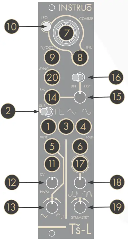
Key
| 1. Square Output2. Sub Toggle3. Triangle Output4. Sine Output5. PWM Output6. Wavefold Output7. Coarse8. Fine9. 1V/Oct Input10. LFO Button | 11 . PWM CV Input12. PWM CV Attenuverter13 . PWM Waveform Crossfade14. FM Input15 . FM Attenuator16. Lin/Exp Toggle17. Wavefold CV Input18. Wavefold Depth / CV Attenuator19. Symmetry Bias Attenuverter20. Soft Sync Input |
Waveforms
![]() Square Output: Square waveform output.
Square Output: Square waveform output.![]() Triangle Output: Triangle waveform output.
Triangle Output: Triangle waveform output.![]() Sine Output: Sine waveform output.Pulse Output: Pulse width modulation waveform output.
Sine Output: Sine waveform output.Pulse Output: Pulse width modulation waveform output.
- This waveform is unlike any other. It smoothly morphs from a split triangle waveform to a slightly softened stepped triangle waveform.

Wave fold Output: Final waveform output.
- The waveform is determined by the Wavefold Attenuator and the Symmetry Bias parameter.
Frequency/Pitch
Coarse: The Coarse knob controls the fundamental frequency of the oscillator. It determines the pitch of all waveforms.
- Turning the knob anticlockwise will decrease the frequency.
- Turning the knob clockwise will increase the frequency.
Fine: The Fine knob is used for minute control of the oscillator’s fundamental frequency and is relative to the frequency value set by the Coarse knob. This will also determine the pitch of all waveforms.
- Turning the knob anticlockwise will decrease the frequency.
- Turning the knob clockwise will increase the frequency.
1 V/Oct Input: The 1 V/Oct Input is a bipolar control voltage input that is calibrated to 1 volt per Octave.
- This is traditionally used for frequency control (musical pitch) sent from a sequencer or keyboard.
- Control voltage is summed with the values set by the Coarse and Fine knobs
LFO Button: The LFO Button enters LFO Mode turning Ti-L into a fully functional low-frequency oscillator. LFO Mode drops the frequency, forcing all waveform outputs to oscillate within subsonic frequency ranges (The highest rate in LFO Mode is 220Hz).
Sub Toggle: The Sub Toggle determines the octave of the square waveform.
- If the toggle is set to the centre position, the frequency of the square waveform is set to the fundamental frequency, tuned to unison with the other waveforms.
- If the toggle is set to the right position, the frequency of the square waveform is set to one octave below the fundamental frequency of the oscillator.
- If the toggle is set to the left position, the frequency of the square waveform is set to two octaves below the fundamental frequency of the oscillator.
Pulse Width Modulation
PWM: The PWM parameter controls the width of the pulses for the PWM waveform.
- Turning the knob anticlockwise will decrease the width of the pulses.
- Turning the knob clockwise will increase the width of the pulses.
PWM CV Input: The PWM CV Input is a bipolar control voltage input for the PWM parameter.
- Control voltage is summed with to the PWM knob position.
- Input range: –/+5V.
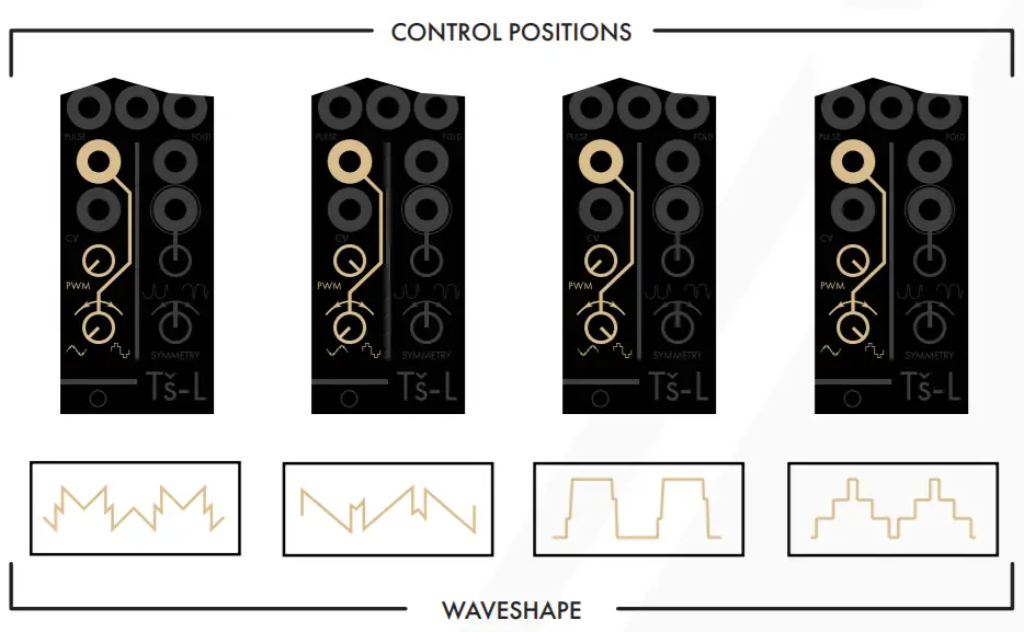
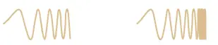
PWM Waveform Crossfade: The PWM Waveform Crossfade knob controls the blend between two parallel PWM controlled waveforms produced by Tš-L.
- Turning the knob anticlockwise will blend towards the splittriangle waveform.
- Turning the knob clockwise will blend towards the stepped triangle waveform.
Frequency Modulation
FM Input: The FM Input is a bipolar control voltage input for the frequency parameter of the oscillator.
- Control voltage is summed with the values set by the Coarse and Fine knobs and scaled by the FM Attenuator.
FM Attenuator: The FM Attenuator determines the depth of frequency modulation applied to the fundamental frequency.

- Turning the knob anticlockwise will decrease the depth of frequency modulation.
- Turning the knob clockwise will increase the depth of frequency modulation.
Lin/Exp Toggle: The FM Input can be set to have a linear or exponential FM response curve.
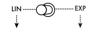 |
If the toggle is set to the left position, the FM signal will apply with linear scaling. |
 |
If the toggle is set to the right position, the FM signal will apply with exponential scaling. |
- If the toggle is set to exponential FM and the FM Attenuator is fully clockwise, the FM Input will essentially track at 1V/Octave (Its tracking may differ slightly from the calibrated 1V/Oct Input).
Wavefolding
Wave fold: The Wavefold knob controls the amount of wavefolding applied to the waveform produced at the Wavefold Output.
- A parallel sine waveform is used by the wavefolder.
- Turning the knob fully anticlockwise results in a waveform that resembles a sine waveform.
- Turning the knob fully clockwise results in a rich, harmonic timbre (Adjusting the Symmetry Bias knob will further affect the harmonic makeup).
Wave fold CV Input: The Wavefold CV Input is a unipolar positive control voltage input that can be scaled by the Wavefold knob.
- When the external control voltage is used to control the wavefolder, the Wavefold knob becomes an attenuator over the external control voltage signal.
Symmetry Bias: The Symmetry Bias knob controls a DC offset amount that shapes the sine waveform used by the wavefolder. The amount of DC offset is applied before the wavefolding stage.
- The Symmetry Bias parameter offsets the curvature of the raw sine waveform that becomes further shaped by the wavefolder.
- Applied Symmetry Bias will affect the harmonic makeup of the final
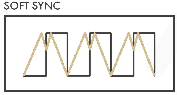
Soft Synchronisation/Phase Locking
- Soft Sync Input: Tš-L implements Soft Synchronisation.
- This is also known as Frequency Lock or X-Lock.
- The oscillator’s core triangle waveform changes its charge direction when clocked.
- When tuning the oscillator to an external signal, the Soft Sync Input can be used to phase lock the signals to remove beat frequencies in unison and perfect interval tunings.
- Tš-L will lock to integer multiples of the external signal.
- Musical intervals such as perfect octaves, perfect 4ths, and perfect 5ths work best for the Soft Sync Input.
- Voltage threshold: 2V.
Patch Examples
East Coast Synth Voice:Summary: The sequencer or keyboard sends voltages to Tš-L while simultaneously triggering the envelope generator. The CV output of the envelope generator opens the filter and VCA, allowing Tš-L’s signal to pass through. More traditional East Coast patches would incorporate separate envelope generators for the filter and VCA.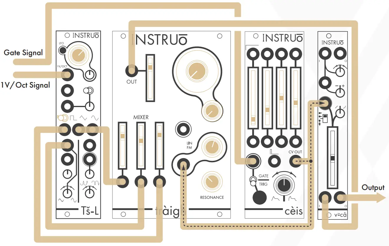
Audio Path:
- Connect the Square, Pulse, and Triangle waveforms of Tš-L to three inputs of a mixer.
- Set the Sub Toggle to its left position, dropping the square waveform by one octave.
- Connect the output of the mixer to the audio input of a filter.
- Connect the audio output of the filter to the audio input of a VCA.
- Monitor the output of the VCA.
- Set the fundamental frequency of Tš-L to the desired position.
- Set the individual levels of the mixer to desired positions.
- Set the cutoff frequency of the filter to the desired position.
- Set the resonance of the filter to the desired position.
- Set the level of the VCA to the desired position.
Control Path:
- Connect the 1V/Oct output of a sequencer or keyboard to the 1V/Oct input of Tš-L.
- Connect the gate output of the sequencer or keyboard to the trigger input of an envelope generator.
- Connect the CV output of the envelope generator to a multiple.
- Connect one copy of the envelope generator CV signal to the CV input of the filter and set the corresponding CV attenuator to the desired position.
- Connect a second copy of the envelope generator CV signal to the CV input of the VCA and set the corresponding CV attenuator to the desired position.
- Set the envelope stages to desired positions.
FM Synth Voice:Summary: The secondary oscillator, called the Modulator in an FM patch, is modulating the frequency of Tš-L, called the carrier in an FM patch. The sequencer or keyboard sends voltages to Tš-L while simultaneously triggering the envelope generator. The CV output of the envelope generator opens the filter and VCA, allowing Tš-L’s signal to pass through. More traditional East Coast patches would incorporate separate envelope generators for the filter and VCA.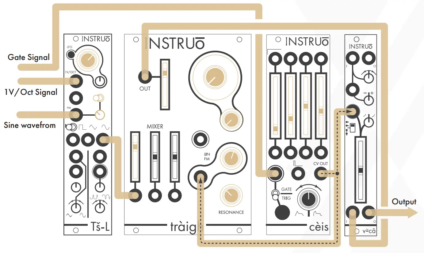
Audio Path:
- Create an East Coast Synth Voice audio path using the sine waveform of Tš-L.
Control Path:
- Create an East Coast Synth Voice control path.
- Connect the sine waveform of a separate oscillator to the FM Input of Tš-L.
- Set the FM Attenuator to the desired position.
- Set the Lin/Exp Toggle to the desired position.
- Most East Coast synthesizers were traditionally limited to linear frequency modulation only.
Folded PWM Synth Voice:Summary: Connecting the PWM Output to the Wavefold CV Input allows for four levels of timbre control via the PWM knob/PWM CV Input, the PWM Waveform Crossfade knob, the Wavefold knob, and the Symmetry Bias knob. The sequencer or keyboard sends voltages to Tš-L while simultaneously triggering the envelope generator. The CV output of the envelope generator opens the filter and VCA, allowing Tš-L’s signal to pass through. More traditional East Coast patches would incorporate separate envelope generators for the filter and VCA.
Audio Path:
- Create an East Coast Synth Voice audio path using the Wavefold Output of Tš-L.
- Set the Wavefold knob to the desired position.
- Set the Symmetry Bias knob to the desired position.
Control Path:
- Create an East Coast Synth Voice control path.
- Connect the Pulse Output to the Wavefold CV Input.
- Set the PWM knob to the desired position.
- Set the PWM Waveform Crossfade knob to the desired position.
Manual Author: Collin RussellManual Design: Dominic D’Sylva
 report this ad
![]() This device meets the requirements of the following standards: EN55032,EN55103-2, EN61000-3-2, EN61000-3-3, EN62311.
This device meets the requirements of the following standards: EN55032,EN55103-2, EN61000-3-2, EN61000-3-3, EN62311.
[xyz-ips snippet=”download-snippet”]