athrúWavefolderUser Manual
Description
The Instruō athrú is a full-featured analog wavefolder that creates incredibly complex timbres from very basic waveforms using an interesting form of distortion.Unlike traditional distortion effects where signal amplitudes passing a threshold are ‘clipped’, wave folding inverts signal amplitude when it passes an amplitude threshold. This folding can occur multiple times, resulting in dynamic control over rich harmonic spectra.In subtractive synthesis, partials are attenuated from harmonically dense waveforms. athrú, on the other hand, utilizes additive synthesis by generating partials from harmonically simple waveforms.Starting out as a derivative of the West Coast timbre circuit, the wave folders in the Instruō system have been tweaked and adapted with each incarnation. athrú is the latest incarnation in a stand-alone package.Depth control via an exponential VCA, summing with a scalable symmetry bias offers everything from subtle boosts in harmonics to full-on spectral devastation.
Features
- Wavefolding
- Symmetry bias with summing capabilities.
- Strike input with definable decay
- Analog drive
Installation
- Confirm that the Eurorack synthesizer system is powered off.
- Locate 4 HP of space in your Eurorack synthesizer case.
- Connect the 10 pin side of the IDC power cable to the 2×5 pin header on the back of the module, confirming that the red stripe on the power cable is connected to -12V.
- Connect the 16 pin side of the IDC power cable to the 2×8 pin header on your Eurorack power supply, confirming that the red stripe on the power cable is connected to -12V.
- Mount the Instruō athrú in your Eurorack synthesizer case.
- Power your Eurorack synthesizer system on.
Note:This module has reverse polarity protection.Inverted installation of the power cable will not damage the module.
Specifications
- Width: 4 HP
- Depth: 39mm
- +12V: 30mA
- -12V: 30mA
athrú | ‘ɑ:ɾ·u: | verb (mathematics) an act or process through which something becomes different; to change, transform, alteration, variation and mutation

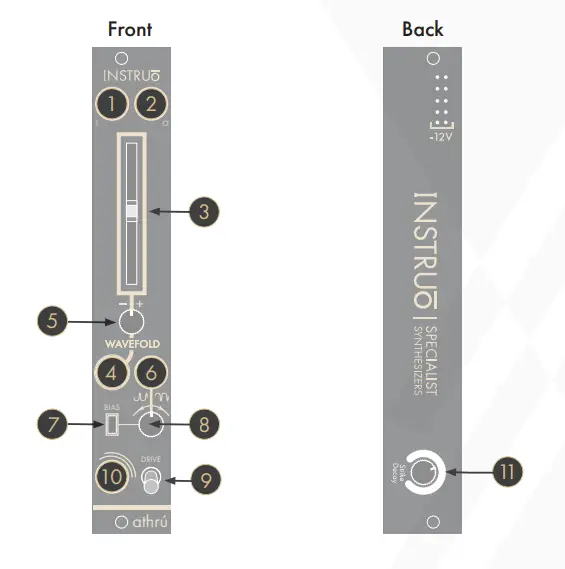
| 1. Input | 7. Symmetry Bias Switch |
| 2. Output | 8. Symmetry Bias Attenuverter |
| 3. Wave fold | 9. Drive Toggle |
| 4. Wavefold CV Input | 10. Strike Input |
| 5. Wavefold Attenuverter | 11 . Strike Decay |
| 6. Symmetry Bias Input |
Any athrú after Nov 2020 has a slightly different layout that places the Strike Decay on the front of the module in the form of a trim pot. The Drive Toggle is also mounted horizontally instead of vertically

| 1. Input | 7. Symmetry Bias Switch |
| 2. Output | 8. Symmetry Bias Attenuverter |
| 3. Wave fold | 9. Drive Toggle |
| 4. Wavefold CV Input | 10. Strike Input |
| 5. Wavefold Attenuverter | 11 . Strike Decay |
| 6. Symmetry Bias Input |
Wavefolding
Input: DC-coupled signal input.Output: DC-coupled signal output.Wave fold: The Wavefold fader controls the amount of wave folding applied to the signal present at the Input. The folded signal is present at the Output.
- Moving the fader fully downwards will reduce the Input signal’s amplitude, resulting in near-silence.
- Moving the fader fully upwards results in a rich, harmonic timbre (If the Symmetry Bias Switch is in the up position, adjusting the Symmetry Bias Attenuverter will further affect the harmonic spectrum).
Wave fold CV Input: The Wavefold CV Input is a bipolar control of the voltage input for the Wavefold parameter that utilizes an exponential VCA.
- Control voltage is summed with the fader position following its inbuilt attenuverter.
Wave fold Attenuverter: The Wavefold Attenuverter will scale and invert the control voltage signals present at the Wavefold CV Input.Symmetry Bias Input: A signal present at the Symmetry Bias Input will replace the normally reference DC voltage. The external signal can be scaled and inverted via the Symmetry Bias Attenuverter. The incoming signal sums with the Input signal before reaching the wave folding stage.
- External signals can be processed via the Symmetry Bias Input. The Symmetry Bias Attenuverter controls the external signal’s amplitude. Decreasing the amount of wave folding via the Wavefold fader will isolate only the second external signal at the Output.
Symmetry Bias Switch: The Symmetry Bias Switch changes the behavior of the Symmetry Bias Attenuverter.Symmetry Bias Attenuverter: The Symmetry Bias Attenuverter can function in two ways depending on the position of the Symmetry Bias Switch.
 When the switch is in the down position, the Symmetry Bias Attenuverter functions as an attenuverter for incoming control voltage or audio signals. This means that control voltage can be applied to the parameter or two audio signals can be summed together before reaching the wave folding stage. Turning the knob anticlockwise will scale and invert the incoming control voltage or audio signal. Turning the knob clockwise will scale the incoming control voltage or audio signal.


- The center position of this knob is calibrated to 0V.
Drive Toggle: Analog overdrive can be applied to the signal present at the input, resulting in soft harmonic distortion.
- If the toggle is in the up position, overdrive is enabled. If the toggle is in the down position, overdrive is disabled.


- (For all athrú after Nov 2020) If the toggle is in the right position, overdrive is enabled. If the toggle is in the left position, overdrive is disabled.


Strike Input: A gate or trigger signal present at the Strike Input will momentarily activate the wavefolder.Strike Decay: The decay of the Strike Input can be adjusted via the Strike Decay knob located on the back of the module (front trim pot on any athrú after Nov 2020) .Turning the knob anticlockwise will decrease the decay time. Turning the knob clockwise will increase the decay time. The default position is 50%.


Patch Examples
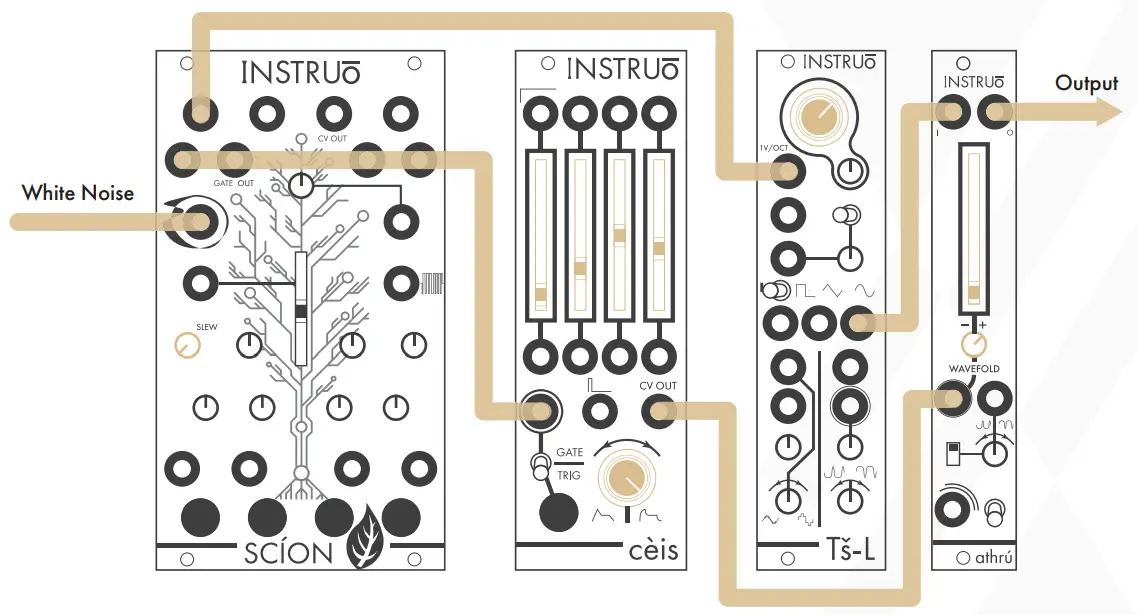
West Coast Synth Voice:Summary: The random voltage generator sends voltages to the oscillator while simultaneously triggering the envelope generator. The CV output of the envelope generator opens athrú, allowing the oscillator signal to pass through.


Audio Path:
- Connect the desired waveform of an oscillator to the Input of athrú.
- Monitor the output of the athrú.
- Set the fundamental frequency of the oscillator to the desired position.
- Set the Wavefold fader to its minimum setting.
Control Path:
- Connect the stepped random output of a random voltage generator to the 1V/Oct input of the oscillator.
- Connect the gate output of the random voltage generator to the trigger input of an envelope generator.
- Connect the CV output of the envelope generator to the Wavefold CV Input of athrú and set the Wavefold Attenuverter to a desired positive position.
- Set the envelope stages to desired positions.
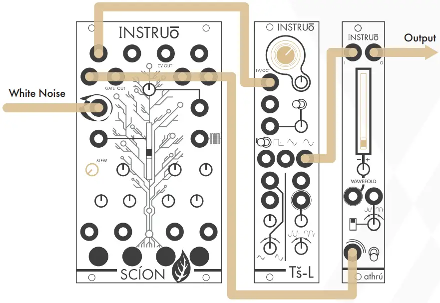
West Coast Bongo:Summary: The random voltage generator sends voltages to the oscillator while simultaneously striking athrú, allowing the oscillator signal to pass through.


Audio Path:
- Connect the desired waveform of an oscillator to the Input of athrú.
- Monitor the output of the athrú.
- Set the fundamental frequency of the oscillator to the desired position.
- Set the Wavefold fader to its minimum setting.
Control Path:
- Connect the stepped random output of a random voltage generator to the 1V/Oct input of the oscillator.
- Connect the gate output of the random voltage generator to the Strike Input of athrú.
Summed Wavefolder:Summary: Two waveforms are summed via the Input and Symmetry Bias Input and then sent through the wavefolder.


- Create a West Coast Synth Voice audio path.
- Connect the desired waveform from a secondary oscillator to the Symmetry Bias Input.
- Set the Symmetry Bias Switch to the down position and set the Symmetry Bias Attenuverter fully clockwise.
- Set the Drive toggle to the up position for added distortion.
Burst Generator:Summary: Everytime cèis is triggered, a burst of trigger signals will stike athrú allowing the oscillator signal to pass through. For added modulation, multiply the combined trigger output signal and connect it to both the Strike Input of athrú and the clock input of a random voltage generator and connect the CV output of the random voltage generator to the 1V/Oct input of the oscillator.


Audio Path:
- Create the West Coast Synth Voice audio path.
Control Path:
- Connect the combined trigger output of cèis to the strike input of athrú.
- Set the separate envelope stages at different positions to create the desired trigger burst.
- Trig Button.
Manual Author: Collin RussellManual Design: Dominic D’Sylva

[xyz-ips snippet=”download-snippet”]
