Cš-LComplex OscillatorUser Manual
Description
The Instruō Cš-L is a dual analog oscillator optimized for the generation of complex waveforms. It features two contrasting discrete circuit oscillators that are normally to one another, offering a variety of simultaneousmodulation routings. The resulting harmonic timbres sit far beyond the realms of traditional subtractive synthesis.It expands upon the classic complex oscillator paradigm prominent in the West Coast synthesis philosophy. Typical cross-modulation is expanded upon with the inclusion of signal multiplication/amplitude modulation, a wavefolder per oscillator, final waveform symmetry biasing, classic and contemporary PWM, a global modulation index bus, and a digitally-controlled routing scheme that can be configured on the fly.With the two separate oscillator cores, simultaneous access to all included waveforms, and the ability for bi-directional modulation, the Cš-L truly allows the user to shape sound like never before.
Features
- Two independent contrasting cored analog oscillators
- Wavefolder per oscillator
- Waveform symmetry biasing
- 1V/Oct linking for parallel tracking
- Four-quadrant signal multiplication/amplitude modulation
- Internal oscillator sync capabilities
- Digitally-controlled internal modulation routing
- Global modulation index bus
- LFO capabilities
- Sub-square modes
Installation
- Confirm that the Eurorack synthesizer system is powered off.
- Locate 26 HP of space in your Eurorack synthesizer case.
- Connect the 10 pin side of the IDC power cable to the 2×5 pin header on the back of the module, confirming that the red stripe on the power cable is connected to -12V.
- Connect the 16 pin side of the IDC power cable to the 2×8 pin header on your Eurorack power supply, confirming that the red stripe on the power cable is connected to -12V.
- Mount the Instruō Cš-L in your Eurorack synthesizer case.
- Power your Eurorack synthesizer system on.
Note:This module has reverse polarity protection.Inverted installation of the power cable will not damage the module.
Specifications
- Width: 26 HP
- Depth: 35mm
- +12V: 200mA
- -12V: 80mA
Key
| 1. Osc A 1V/Oct Input2. Osc A Coarse Frequency3. Osc A Fine Frequency4. Osc A Sine Output5. Osc A Triangle Output6. Osc A Sawtooth Output7. Osc A Final Output8. Mod Button9. Osc A PWM Output10. Osc A PWM CV Input11 . Osc A PWM12. Osc B 1V/Oct Input13 . Osc B Coarse Frequency14. Osc B Fine Frequency | 15 . Osc B Sine Output16. Osc B Square Output17. Sub Button18. Osc B Triangle Output19. Osc B Final Output20. Osc B PWM Output21. Osc B PWM CV Input22. Osc B PWM23. Multiply Output24. Multiply Modulator Input25. Multiply Carrier Input26. Depth27. Ring/AM/Rect Button |
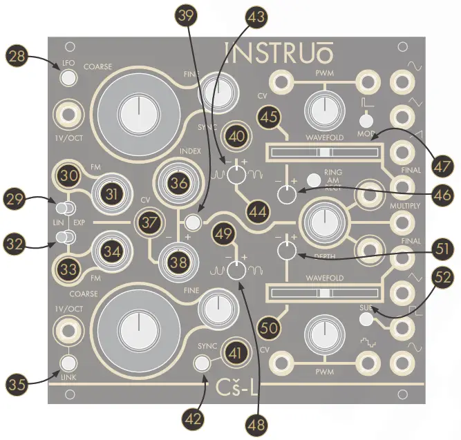
| 28. LFO Button29. Osc A-Lin/Exp Toggle30. Osc A FM Input31. Osc A FM Attenuator32. Osc B Lin/Exp Toggle33. Osc B FM Input34. Osc B FM Attenuator35. Link Button36. Index Knob37. Index CV Input38. Index Attenuverter39. Index Button40. Hard Sync Input | 41. Soft Sync Input42. Sync Button43. Osc A Symmetry Bias Attenuverter44. Osc A Symmetry Bias Input45. Osc A Wavefold CV Input46. Osc A Wavefold Annenuverter47. Osc A Wavefold Fader48. Osc B Symmetry Bias Attenuverter49. Osc B Symmetry Bias Input50. Osc B Wavefold CV Input51. Osc B Wavefold Annenuverter52. Osc B Wavefold Fader |
Oscillators
Oscillators A and B share various similarities, but they utilize very different circuitry architectures. Oscillator A features a sawtooth core circuit while Oscillator B features a triangle core circuit. This contrast in cores results in slight variations in the harmonic content of each oscillators’ available waveforms and their strengths and weaknesses.In short, sawtooth core circuits can do certain things better than triangle core circuits, and vice versa. The Cš-L offers the best of both worlds It is important to note that, because of their different architectures andconfigurations, each oscillator has a different global frequency range.This means that matching pointer positions on the Coarse and Fine frequency knobs will not necessarily result in matching output frequencies.The peak-to-peak amplitude of the various waveform outputs differs from each other slightly. The reference point is 10Vpp on the sawtooth wave. The other signal amplitudes were purposefully chosen to give a morebalanced perceived loudness over a musical range. This effect is most prominent between the more harmonically rich waveforms.
Oscillator A (Sawtooth Core)
|
Sine Output: Sine waveform output.Triangle Output: Triangle waveform output.Sawtooth Output: Sawtooth/Ramp waveform output. |
Final Output: Final waveform output.
- The waveform is determined by the Wavefold parameter and the Symmetry Bias Attenuverter.
PWM Output: Pulse width modulation waveform output.

|
PWM: The PWM knob controls the duty cycle ratio of the pulse width modulation waveform. |
- Turning the knob clockwise will increase the +/– ratio of the pulse wave.
- Turning the knob anticlockwise will decrease the +/– ratio of the pulse wave.
- The range of the PWM knob was chosen to always result in a signal with an audible duty cycle when used without external control voltage.PWM CV Input: The PWM CV Input is a bipolar control voltage input for the PWM parameter.
- Control voltage sums with the PWM knob position.
- Input range: -/+5V.
- Note that with external control voltage extending the controllable range of the duty cycle, the audibility of the signal will drop when pushed beyond 0% and 100%.
LFO Button: The LFO Button will switch Oscillator A to sub-audio range frequencies.
 If the LFO Button is unilluminated, Oscillator A will output audio range frequencies.
- Oscillator A will continue to track 1V/Octave when set to LFO Mode.
- The LFO will reset with every rising edge signal present at the Hard Sync Input of Oscillator A.
- If the LFO Button is illuminated white, Oscillator A will output sub-audio range frequencies.
LFO Hard Sync

Oscillator B (Triangle Core)Final Output: Final waveform output.
- The waveform is determined by the Wavefold parameter and the Symmetry Bias Attenuverter.Triangle Output: Triangle waveform output.Square Output: Square waveform output.
Sub Button: The Sub Button determines the octave of the Square Output.
![]() If the Sub Button is unilluminated, the square waveform is set to the fundamental frequency of Oscillator B.
If the Sub Button is unilluminated, the square waveform is set to the fundamental frequency of Oscillator B.![]() If the Sub Button is illuminated white, the square waveform is set to one octave below the fundamental frequency of Oscillator B.
If the Sub Button is illuminated white, the square waveform is set to one octave below the fundamental frequency of Oscillator B.![]() If the Sub Button is illuminated amber, the square waveform is set to two octaves below the fundamental frequency of Oscillator B.
If the Sub Button is illuminated amber, the square waveform is set to two octaves below the fundamental frequency of Oscillator B.![]() Sine Output: Sine waveform output.
Sine Output: Sine waveform output.
PWM Output: Stepped triangle waveform output.
![]()
PWM: The PWM knob controls the width of the upper and lower pulses of the stepped triangle waveform.
- Turning the knob clockwise will increase the width of the upper and lower pulses.
- Turning the knob anticlockwise will decrease the width of the upper and lower pulses.
- The range of the PWM knob was chosen to always result in a signal with an audible duty cycle when used without external control voltage.
PWM CV Input: The PWM CV Input is a bipolar control voltage input for the PWM parameter.
- Control voltage sums with the PWM knob position.
- Input range: -/+5V.
- Note that with external control voltage extending the controllable range of the duty cycle, the audibility of the signal will drop when pushed beyond 0% and 100%.
Frequency/Pitch
Coarse: The Coarse knob controls the fundamental frequency of the oscillator. It determines the pitch of all corresponding waveforms.
- Turning the knob clockwise will increase the frequency.
- Turning the knob anticlockwise will decrease the frequency.
Fine: The Fine knob is used for minute control of the oscillator’s fundamental frequency and is relative to the frequency value set by theCoarse knob. It also determines the pitch of all corresponding waveforms.
- Turning the knob clockwise will increase the frequency.
- Turning the knob anticlockwise will decrease the frequency.
1V/Oct Input: The 1V/Oct Input is a bipolar control voltage input that is calibrated to 1V per octave.
- This is traditionally used for frequency control (musical pitch) sent from a sequencer or keyboard.
- Control voltage is added to the summed values set by the Coarse and Fine knobs.
The Link Button will bidirectionally normal 1V/Octave control voltage signals from one oscillator to the other via either 1V/Oct Input.
![]() If the Link Button is unilluminated, linking is disabled, and the 1V/Oct Input will control the corresponding oscillator only.
If the Link Button is unilluminated, linking is disabled, and the 1V/Oct Input will control the corresponding oscillator only.![]() If the Link Button is illuminated white, linking is engaged. Sending control voltage to the 1V/Oct Input of Oscillator A only will control both Oscillators A and B. Similarly, sending a control voltage to the 1V/Oct Input of Oscillator B only will control both Oscillators B and A.
If the Link Button is illuminated white, linking is engaged. Sending control voltage to the 1V/Oct Input of Oscillator A only will control both Oscillators A and B. Similarly, sending a control voltage to the 1V/Oct Input of Oscillator B only will control both Oscillators B and A.
- If a second 1V/Octave signal is patched in either of the above configurations the Link routing normally is broken and the oscillators will track independently.
![]()
Frequency Modulation
 |
FM Input: The FM Input is a bipolar control of the voltage input for the frequency parameter of the oscillators. |
- Control voltage is summed with the values set by the Coarse andFine knobs and scaled by the FM Attenuator.
- By default, the sine waveform of Oscillator A is normalled to the FM Input Oscillator B. Similarly, the sine waveform of Oscillator B is normalled to the FM Input Oscillator A.
- An external signal present at the FM Input will break the normal sine waveform connection and act as the modulator.
FM Attenuator: The FM Attenuator determines the depth of frequency modulation applied to the corresponding oscillator.
- Turning the knob clockwise will increase the depth of frequency modulation.
- Turning the knob anticlockwise will decrease the depth of frequency modulation.
Lin/Exp Toggle: Each FM Input can be individually set to a linear or exponential frequency modulation response curve.
- If the toggle is set to the left position, the FM signal will apply with linear scaling.
- If the toggle is set to the right position, the FM signal will apply with exponential scaling.
- If the toggle is set to exponential FM and the FM Attenuator is fully clockwise, the FM Input will essentially track 1V/Octave (Its tracking may differ slightly from the calibrated 1V/Oct Input).
Wavefolding
Wave fold: The Wavefold faders control the amount of wave folding applied to the sine waveform of each respective oscillator. Folded signals are present at the Final Outputs. Unlike traditional distortion effects where signal amplitude passing a threshold is ‘clipped’, wave folding inverts signal amplitude when it passes a threshold. This folding can occur multiple times resulting in dynamic control over rich harmonic spectra.
- The sine waveforms are normal to the Wavefolders.
- Moving the fader fully left will reduce the signal’s amplitude, resulting in near-silence.
- Moving the fader to the center results in a waveform that resembles a sine waveform (depending on the position of the SymmetryBias Attenuverter).
- Moving the fader fully right results in a rich, harmonic timbre (Adjusting the Symmetry Bias Attenuverter will further affect the harmonic makeup).
Wave fold CV Input: The Wavefold CV Input is a bipolar control voltage input for the Wavefold parameter.
- Control voltage is summed with the fader position and scaled by the Wave fold Attenuverter.
Wave fold Attenuverter: The Wavefold Attenuverter will scale and invert the control voltage signals present at the Wavefold CV Input.Symmetry Bias Attenuverter: The Symmetry Bias Attenuverter controls the DC offset amount of the sine waveform normally to the Wavefold input. The amount of DC offset is applied before the wave folding stage.
- By default, a DC reference voltage is normally to the signal attenuverter.
- The center position of this knob is calibrated to 0V.
- Turning the knob anticlockwise applies a negative bias to the normalled sine waveform.
- Turning the knob clockwise applies a positive bias to the normalled sine waveform.
- Applied DC bias will affect the harmonic overtones of the waveform.
Symmetry Bias Input: A signal present at the Symmetry Bias Input will replace the normal reference voltage. The external signal can be scaled and inverted via the Symmetry Bias Attenuverter. The incomingsignal sums with the normalled sine waveform before reaching the wave folding stage.The wave fold circuit can be isolated for processing external signals via the Symmetry Bias Input. The Symmetry Bias Attenuverter controls the amplitude of the external signal. Decreasing the amount of wave folding via the Wavefold fader will isolate only the external signal at the Final Output.
Oscillator Synchronisation
Both oscillators have an external synchronization input, labeled Sync on the front panel.Hard Sync Input: Oscillator A implements Hard Synchronisation.

- On a rising edge signal, the oscillator’s cycle will reset.
- Hard-edged signals such as sawtooth/ramp and square waveforms work best for the Hard Sync Input of Oscillator A.
- Voltage threshold: 2.5V.
Soft Sync Input: Oscillator B implements Soft Synchronisation.
- This is also known as Frequency Lock or X-Lock.
- The oscillator’s core triangle waveform changes its charge direction when clocked.
- When tuning Oscillator B to an external signal, the Soft Sync Input can be used to phase lock the signals to remove beat frequencies in unison and perfect interval tunings.
- Oscillator B will lock to integer multiples of the external signal.
- Musical intervals such as perfect octaves, perfect 4ths, and perfect 5ths work best for the Soft Sync Input of Oscillator B.
- Voltage threshold: 2V.
Sync Button: The Sync Button determines the internal synchronization routing between the two oscillators.
![]() When the Sync Button is unilluminated, no internal synchronization is applied.
When the Sync Button is unilluminated, no internal synchronization is applied.![]() When the Sync Button is illuminated amber, the sawtooth/ramp waveform of Oscillator A will normal to the Soft Sync Input of Oscillator B, soft synchronizing Oscillator B to Oscillator A.
When the Sync Button is illuminated amber, the sawtooth/ramp waveform of Oscillator A will normal to the Soft Sync Input of Oscillator B, soft synchronizing Oscillator B to Oscillator A.![]() When the Sync Button is illuminated white, the square waveform of Oscillator B will normal to the Hard Sync Input of Oscillator A, hard synchronizing Oscillator A to Oscillator B.
When the Sync Button is illuminated white, the square waveform of Oscillator B will normal to the Hard Sync Input of Oscillator A, hard synchronizing Oscillator A to Oscillator B.
- Pressing the Sub Button will change the octave of the synchronizing signal.
Amplitude Modulation
The module features an on-board signal multiplier which can be utilized as a four-quadrant multiplier, internal/external signal rectifier, and as a traditional voltage-controlled amplifier.Multiple Inputs: Each oscillators’ sine waveform is normalled to its corresponding Multiple Input jack.
- Signals present at the Multiply Inputs will break the normal sine waveforms and become the sources for signal multiplication.
- Similar to the wave fold circuit, the amplitude modulation circuit can be accessed for use independent of Oscillators A and B.
Multiply Output: Multiplied signal output.
- The timbre is determined by the signals present at theMultiple Inputs.
Depth: The Depth knob determines the amplitude of the top signal applied to the multiplier circuit. Due to the nature of signal multiplication, this effectively controls the resulting amplitude of the output signal.
- In comparison to the rich timbres produced at the Final Outputs, signals produced by the multiplier often appear softer to the ear, even with approximately equal signal amplitudes. Due to this difference in perception, the multiplier has a purposefully increased gain level on its inputs.
- Unity gain of the multiplier can be achieved by setting the pointer of the Depth knob to point approximately at the Multiply Modulator Input (2 o’clock). Once the knob is passed that point, the multiplied signals will clip in a harmonically pleasing way.
Ring/AM/Rect Button: The Ring/AM/Rect Button determines the amplitude modulation mode for the Multiply Modulator Input.
![]() If the button is unilluminated, Ring Modulation Mode is selected.
If the button is unilluminated, Ring Modulation Mode is selected.![]() This mode functions as a full four-quadrant multiplier which achieves bipolar amplitude modulation.
This mode functions as a full four-quadrant multiplier which achieves bipolar amplitude modulation.![]() If the button is illuminated white, Half Wave Rectification Mode is selected. This mode omits any negative portion of the signal seen |
If the button is illuminated white, Half Wave Rectification Mode is selected. This mode omits any negative portion of the signal seen |![]() at the Multiply Input of Oscillator A, cropping the signal to 0V.
at the Multiply Input of Oscillator A, cropping the signal to 0V.![]() If the button is illuminated amber, Full Wave Rectification Mode is selected. This mode inverts any negative portion of the signal seen
If the button is illuminated amber, Full Wave Rectification Mode is selected. This mode inverts any negative portion of the signal seen![]() at the Multiply Input of Oscillator A. This input signal becomes unipolar positive.
at the Multiply Input of Oscillator A. This input signal becomes unipolar positive.
Internal Modulation Routing
There are two internal linear VCAs on the Cš-L. The sine waveforms of each oscillator route to these in parallel with the Sine Outputs. The amplitudes of these VCAs are controlled simultaneously via the Indexbus. Each VCA controlled sine waveform can be routed to up to four modulation destinations, each that can be defined independently without patching a single cable.
![]()
Index: The Index knob simultaneously sets the gain level of the two internal VCAs.
- Turning the knob anticlockwise decreases the global depth of modulation.
- Turning the knob clockwise will increase the global depth of modulation.
Index Attenuverter: The Index Attenuverter will scale and/or invert the control voltage signals present at the Index CV Input.Index CV Input: The Index CV Input is a bipolar control voltage input for the Index parameter.
- Control voltage is scaled and/or inverted by the Index Attenuverter and summed with the Index knob position.
Mod Button: The Mod Button is used to set the internal routing of the Index signals to the opposite oscillators PWM CV Input.
![]() If the button is unilluminated, internal modulation routing is disabled.
If the button is unilluminated, internal modulation routing is disabled.![]() If the button is illuminated white, the sine waveform of Oscillator A is routed to the PWM CV Input of Oscillator B, and vice versa.
If the button is illuminated white, the sine waveform of Oscillator A is routed to the PWM CV Input of Oscillator B, and vice versa.![]() If the button is illuminated amber, the sine waveform of Oscillator A is routed to the PWM CV Input of Oscillator B only.
If the button is illuminated amber, the sine waveform of Oscillator A is routed to the PWM CV Input of Oscillator B only.
Index Button: The Index Button functions as a “shift” control. While pressed down, the other 6 buttons can be used to enable and disable internal modulation routings.
- Pressing the Index Button will display which routings are enabled and disabled. The buttons are illuminated white when the corresponding modulation routing is enabled and illuminated when disabled.
- The Index controlled sine waveforms are used for the internal modulation (Oscillator A can modulate the parameters of Oscillator B and vice versa).

- The internal modulation destinations are as follows:
The Ring/AM/Rect Button is used to enable/disable the modulation routing to the FM Input of Oscillator A (When disabled, the sine waveform of Oscillator B is directly normalled to this destination and not controlled by the Index parameter).The Sync Button is used to enable/disable the modulation routing to the FM Input of Oscillator B (When disabled, the sine waveform of Oscillator A is directly normalled to this destination and not controlledby the Index parameter.).
The Mod Button is used to enable/disable the modulation routing to the Wavefold CV Input of Oscillator A.The Sub Button is used to enable/disable the modulation routing to the Wavefold CV Input of Oscillator B.The LFO Button is used to enable/disable the modulation routing to the Symmetry Bias Input of Oscillator A.
- It is important to note that when enabled, the modulation signal replaces the default reference voltage. The Symmetry Bias Attenuverter will control the inversion and depth of the Index modulation signal.
The Link Button is used to enable/disable the modulation routing to the Symmetry Bias Input of Oscillator B.
- It is important to note that when enabled, the modulation signal replaces the default reference voltage. The Symmetry Bias Attenuverter will control the inversion and depth of the Index modulation signal.
Patch Examples
East Coast Synth Voice:Summary: The sequencer or keyboard sends voltages to Cš-L while simultaneously triggering the envelope generator. The CV output of the envelope generator opens the filter and VCA, allowing Cš-L’s signal topass through. More traditional East Coast patches would incorporate separate envelope generators for the filter and VCA.
Audio Path:
- Connect the Square, PWM, and Triangle waveforms of Oscillator B to three inputs of a mixer.• Set the Sub Button to illuminate white, dropping the square waveform by 1 octave.
- Connect the output of the mixer to the audio input of a filter.
- Connect the audio output of the filter to the audio input of a VCA.
- Monitor the audio output of the VCA.
- Set the Coarse and Fine knobs of Oscillator B to desired positions.
- Set the individual levels of the mixer to desired positions.
- Set the cutoff frequency of the filter to the desired position.
- Set the resonance of the filter to the desired position.
- Set the level of the VCA to the desired position.
Control Path:
- Connect the 1V/Oct output of a sequencer or keyboard to the 1V/Oct Input of Oscillator B.
- Connect the gate output of the sequencer or keyboard to the trigger input of an envelope generator.
- Connect the CV output of the envelope generator to a multiple.
- Connect one copy of the envelope generator CV signal to the CV input of the filter and set the corresponding CV attenuator to the desired position.
- Connect a second copy of the envelope generator CV signal to the CV input of the VCA and set the corresponding CV attenuator to the desired position.
- Set the envelope stages to desired positions.
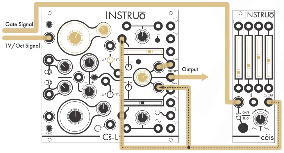
Complete Synth Voice:Summary: The sequencer or keyboard sends note voltages to Cš-L while simultaneously triggering the envelope generator. The CV output of the envelope generator modulates the wavefolder, allowing for timbral changes. The same envelope generator CV signal modulates the Multiple Carrier Input which functions as a VCA. This allows Cš-L’s signal to pass through. More traditional synth voice patches would incorporate separate envelope generators for the wavefolder and Multiply Input.
 Audio Path:
- Connect the Final waveform of Oscillator A to the Multiply Modulator Input.
- Set the Coarse and Fine knobs of Oscillator A to desired positions.
- Set the Wavefold fader of Oscillator A to the desired position.
- Set the Symmetry Bias Attenuverter of Oscillator A to the desired position.
- Monitor the Multiple Output.
Control Path:
- Connect the 1V/Oct output of a sequencer or keyboard to the 1V/Oct Input of Oscillator A.
- Connect the gate output of the sequencer or keyboard to the trigger input of an envelope generator.
- Connect the CV output of the envelope generator to a multiple.
- Connect one copy of the envelope generator CV signal to the Wavefold CV Input of Oscillator A.
- Connect a second copy of the envelope generator CV signal to the Multiply Carrier Input.
- Set the Depth knob to the desired position.
- Set the envelope stages to the desired position.
Sync’d Growl:Summary: Both Final waveforms are multiplied together through a ring modulator. The sine waveform of Oscillator A modulates the Wavefold and Symmetry Bias parameters of Oscillator B while the sine waveform of Oscillator B modulates the same parameters of Oscillator A. The depth of internal modulation is set by the Index knob. The square waveform of Oscillator B hard synchronizes Oscillator A. The sine waveform of Oscillator B frequency modulates Oscillator A. 1V/Octave linking is enabled so that the sequencer or keyboard control voltage signal needs to be present at one 1V/Oct Input only. The sequencer or keyboard sends voltages to Cš-L while simultaneously triggering the envelope generator. The CV output of the envelope generator opens the filter and VCA, allowing Cš-L’s signal to pass through. More traditional East Coast patches would incorporate separate envelope generators for the filter and VCA.
Audio Path:
- Connect both Final waveforms of Cš-L to the respective Multiple Inputs.
- Connect Multiple Output to the audio input of a filter.
- Hard synchronize Oscillator A to the square waveform of Oscillator B by setting the Sync Button so that it illuminates white.
- Connect the audio output of the filter to the audio input of a VCA.
- Monitor the audio output of the VCA.
- Set the Coarse and Fine knobs of both oscillators to desired positions.
- The fundamental frequency of Oscillator B should be set higher than the fundamental frequency of Oscillator A.
- Set the Depth knob to the desired position.
- Set the Wavefold faders of both oscillators to desired positions.
- Set the Symmetry Bias Attenuverters of both oscillators to desired positions.
- Set the level of the VCA to the desired position.
Control Path:
- Enable the 1V/Oct linking by pressing the Link Button so that it illuminates white.
- Enable the modulation routing to the Wavefold CV Input of Oscillator A by holding down the Index Button and then pressing the Mod Button.
- Enable the modulation routing to the Wavefold CV Input of Oscillator B by holding down the Index Button and then pressing the Sub Button.
- Enable the modulation routing to the Symmetry Bias Input of Oscillator A by holding down the Index Button and then pressing the LFO Button.
- Enable the modulation routing to the Symmetry Bias Input of Oscillator B by holding down the Index Button and then pressing the Link Button.
- Set the Index knob to the desired position.
- Set the Lin/Exp Toggle of Oscillator A to the desired response curve.
- Set the FM Attenuator of Oscillator A to the desired position.
- Connect the 1V/Oct output of a sequencer or keyboard to the 1V/Oct Input of Oscillator A.
- Connect the gate output of the sequencer or keyboard to the trigger input of an envelope generator.
- Connect the CV output of the envelope generator to a multiple.
- Connect one copy of the envelope generator CV signal to the CV input of the filter and set the corresponding CV attenuator to the desired position.
- Connect a second copy of the envelope generator CV signal to the CV input of the VCA and set the corresponding CV attenuator to the desired position.
- Set the envelope stages to desired positions.
Formant Voice:Summary: The sine waveform of Oscillator A is half-wave rectified and the square waveform of Oscillator B is lowered by one octave and set to hard synchronize Oscillator A. The product of these two signals can be monitored at the Multiply Output where it can then be connected to the rest of the East Coast Synth Voice audio path. The sequencer or keyboard sends voltages to Cš-L while simultaneously triggering the envelope generator. The CV output of the envelope generator opens the filter and VCA, allowing Cš-L’s signal to pass through.
Audio Path:
- Create an East Coast Synth Voice audio path using the Multiply Output.
- Press the Ring/AM/Rect Button so that it is illuminated white and set to Half Wave Rectification mode.
- Press the Sub Button so that it is illuminated amber and the square waveform’s frequency is lowered by two octaves.
- Press the Sync Button so that it is illuminated white and the square waveform of Oscillator B is hard synchronizing Oscillator A.
- Ensure that both FM Attenuators are set fully anticlockwise.
- The frequency of Oscillator B acts as the fundamental frequency.
- Set the Coarse and Fine knobs of Oscillator B to desired positions.
- The frequency of Oscillator A acts as a timbre control.
- Set the Coarse and Fine knobs of Oscillator A to desired positions.
- Set the Depth knob to the desired position.
Control Path:
- Create an East Coast Synth Voice control path.
Spooky Theremin Voice:The sine waveform of Oscillator B is minutely modulated by the LFO sine waveform of Oscillator A. The sequencer or keyboard sends voltages to Cš-L.
Audio Path:
- Monitor from the Sine Output Oscillator B.
- Set the Coarse and Fine knobs of Oscillator B to desired positions.
Control Path:
- Connect the 1V/Oct output of a sequencer or keyboard to the 1V/Oct Input of Oscillator A.
- Press the LFO Button so that it is illuminated white and LFO Mode is enabled.
- Set the Coarse knob of Oscillator A to 4:00 (around 4Hz) and use the Fine knob of Oscillator A for fine-tuning the frequency.
- Set the Lin/Exp Toggle of Oscillator B to a linear response curve.
- Slightly turn the FM Attenuator of Oscillator B to the desired position.A little goes a long way.
Wave fold to multiply with sync and FM:Summary: Oscillator A is hard synchronized to the Square waveform of Oscillator B. The Final waveform of Oscillator A is multiplied with the sine waveform of Oscillator B. The Sine waveform of Oscillator B alsomodulates the frequency of Oscillator A. The sequencer or keyboard sends voltages to Oscillator B, effectively changing the fundamental frequency of the sound source. Oscillator A acts as a timbre control.
Audio Path:
- Connect the Final Output of Oscillator A to the Multiply Modulator Input.
- Monitor the Multiple Output.
- Press the Sync Button so that it is illuminated white and Hard Synchronisation is enabled.
- Set the Coarse and Fine knobs of both oscillators to desired positions.
- Set the Wavefold fader of Oscillator A to a desired position.
- Set the Symmetry Bias Attenuverter of Oscillator A to a desired position.
- Set the FM Attenuator of Oscillator A to a desired position.
- Set the Lin/Exp Toggle of Oscillator A to a desired position.
- Set the Depth knob to a desired position.
Control Path:
- Connect the 1V/Oct output of a sequencer or keyboard to the 1V/Oct Input of Oscillator B.
The Bonnie Racket Voice:The PWM output of both oscillators is ring-modulated. The ring modulated signal sums with the Sine waveform of Oscillator A and is then sent through the wavefolder. Both oscillators exponentially frequencymodulate each other. The Final Output of Oscillator A can then be connected to the rest of the East Coast Synth Voice audio path. The sequencer or keyboard sends voltages to Cš-L while simultaneously triggering the envelope generator. The CV output of the envelope generator opens the filter and VCA, allowing Cš-L’s signal to pass through. More traditional East Coast patches would incorporate separate envelope generators for the filter and VCA.
Audio Path:
- Create an East Coast Synth Voice audio path using the Final Output of Oscillator A.
- Connect the PWM Output of Oscillator A to the Multiply Carrier Input.
- Connect the PWM Output of Oscillator B to the Multiply Modulator Input.
- Connect the Multiply Output to the Symmetry Bias Input of Oscillator A.
- Press the Sync Button so that it is illuminated white and Oscillator B is hard synchronizing Oscillator A.
- Press the Mode button so that it is illuminated white and Index modulation is applied to the PWM CV Inputs of both Oscillators.
- Set the Lin/Exp Toggles of both oscillators to an exponential response curve.
- Set the FM Attenuators of both oscillators to desired positions.
- Set the PWM knobs of both oscillators to desired positions.
- Set the Coarse and Fine knobs of both oscillators to desired positions.
- Set the Wavefold fader of Oscillator A to the desired position.
- Set the Symmetry Bias Attenuverter of Oscillator A to the desired position.
- Set the Multiply Output to the desired position.
- Set the Index knob to a desired position.
Control Path:
- Create an East Coast Synth Voice control path.
Five Seperate Modules At Once:
Osc A as LFO:
- Press the LFO Button so that the button is illuminated white.
- Set the Coarse and Fine knobs to a desired position.
- Output from any of the waveform outputs of Oscillator A.
Osc A as Wavefolder:
- Ensure that the Wavefold fader is set to its minimum position (fully left).
- Patch an external audio rate signal to the Symmetry Bias Input.
- Set the Symmetry Bias Attenuverter to a desired position. This parameter controls the amount of wavefolding applied to the signal.
- Monitor the Final Output of Oscillator A.
Osc B as Oscillator:
- Set the Coarse and Fine knobs to a desired position.
- Ensure that the 1V/Oct output of a sequencer or keyboard is connected to the 1V/Oct Input of Oscillator B.
- Press the Sub Button so that the button is illuminated white, and the square waveform’s frequency is lowered by one octave.
Multiply as VCA:
- Connect an audio signal to the Multiply Carrier Input.
- Connect a control voltage signal to the Multiply Modulator Input.
- Ensure that Ring Modulation Mode is set and the Ring/AM/Rect
Button is unilluminated
- Set the Depth knob to a desired position.
- Monitor the Multiple Output.
OSC B as Wavefolder:
- Ensure that the Wavefold fader is set to its minimum position (fully left).
- Patch an external audio rate signal to the Symmetry Bias Input.
- Set the Symmetry Bias Attenuverter to a desired position. This parameter controls the amount of wavefolding applied to the signal.
- Monitor the Final Output of Oscillator B.
report this adManual Author: Collin RussellManual Design: Dominic D’Sylva![]() This device meets the requirements of the following standards: EN55032,EN55103-2, EN61000-3-2, EN61000-3-3, EN62311.
This device meets the requirements of the following standards: EN55032,EN55103-2, EN61000-3-2, EN61000-3-3, EN62311.
[xyz-ips snippet=”download-snippet”]