Intellijel 440057 Design Audio Interface II User Manual
Audio I/OEurorack <-> Line Level Audio InterfaceRevision: 2021.08.16
COMPLIANCE

This device complies with Part 15 of the FCC Rules. Operation is subject to the following two conditions: (1) this device may not cause harmful interference, and (2) this device must accept any interference received, including interference that may cause undesired operation.
Changes or modifications not expressly approved by Intellijel Designs, Inc. could void the user’s authority to operate the equipment.
Any digital equipment has been tested and found to comply with the limits for a Class A digital device, pursuant to part 15 of the FCC Rules. These limits are designed to provide reasonable protection against harmful interference when the equipment is operated in a commercial environment. This equipment generates, uses, and can radiate radio frequency energy and, if not installed and used in accordance with the instruction manual, may cause harmful interference to radio communications.
This device meets the requirements of the following standards and directives:
EMC: 2014/30/EUEN55032:2015 ; EN55103-2:2009 (EN55024) ; EN61000-3-2 ;EN61000-3-3
Low Voltage: 2014/35/EUEN 60065:2002+A1:2006+A11:2008+A2:2010+A12:2011
RoHS2: 2011/65/EU
WEEE: 2012/19/EU
INSTALLATION
Intellijel Eurorack modules are designed to be used with a Eurorack-compatible case and power supply. We recommend you use Intellijel cases and power supplies.
Before installing a new module in your case, you must ensure your power supply has a free power header and sufficient available capacity to power the module:
- Sum up the specified +12V current draw for all modules, including the new one. Do the same for the -12 V and +5V current draw. The current draw will be specified in the manufacturer’s technical specifications for each module.
- Compare each of the sums to specifications for your case’s power supply.
- Only proceed with installation if none of the values exceeds the power supply’s specifications. Otherwise you must remove modules to free up capacity or upgrade your power supply.
You will also need to ensure your case has enough free space (hp) to fit the new module. To prevent screws or other debris from falling into the case and shorting any electrical contacts, do not leave gaps between adjacent modules, and cover all unused areas with blank panels. Similarly, do not use open frames or any other enclosure that exposes the backside of any module or the power distribution board.
You can use a tool like ModularGrid to assist in your planning. Failure to adequately power your modules may result in damage to your modules or power supply. If you are unsure, please contact us before proceeding.
Installing Your Module
When installing or removing a module from your case always turn off the power to the case and disconnect the power cable. Failure to do so may result in serious injury or equipment damage.
Ensure the 10-pin connector on the power cable is connected correctly to the module before proceeding. The red stripe on the cable must line up with the -12V pins on the module’s power connector. The pins are indicated with the label -12V, a white stripe next to the connector, the words “red stripe”, or some combination of those indicators.
 Most modules will come with the cable already connected but it is good to double check the orientation. Be aware that some modules may have headers that serve other purposes so ensure the cable is connected to the right one.
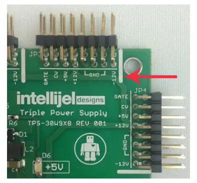
The other end of the cable, with a 16-pin connector, connects to the power bus board of your Eurorack case. Ensure the red stripe on the cable lines up with the -12V pins on the bus board. On Intellijel power supplies the pins are labelled with the label “-12V” and a thick white stripe:
If you are using another manufacturer’s power supply, check their documentation for instructions.
Once connected, the cabling between the module and power supply should resemble the picture below:
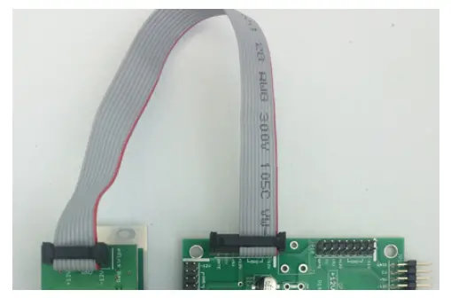
Before reconnecting power and turning on your modular system, double check that the ribbon cable is fully seated on both ends and that all the pins are correctly aligned. If the pins are misaligned in any direction or the ribbon is backwards you can cause damage to your module, power supply, or other modules.
After you have confirmed all the connections, you can reconnect the power cable and turn on your modular system. You should immediately check that all your modules have powered on and are functioning correctly. If you notice any anomalies, turn your system off right away and check your cabling again for mistakes.
OVERVIEW
The Audio I/O allows you to interface your Eurorack modular system to the pro balanced line level world (+4 dBu). You can send and return to rack mount/desktop fx units, patch to external line level instruments like synths and drum machines, interface to a DAW and much more.
FEATURES
- 2 x Balanced TRS 1/4″ to Eurorack modular level input paths
- 2 x Eurorack modular level signals to Balanced TRS 1/4″ output paths
- 4 x six stage led VU meter to monitor all inputs and outputs simultaneously
- Uses high quality THAT Corp balanced line drivers and receiver ICs
- Input path has up to 20 dB of gain which allows you to patch in low level consumer level signals and boost them. 0 dB = 10 Vpp (nominal Eurorack level)
- Output path steps a nominal Eurorack level (10 Vpp) down to +4 dBu with up to +6 dB gain
- Skiff friendly
FRONT PANEL
Controls
[1] INPUT GAIN L/R
These knobs set the gain of the signal coming in to the modular via the BAL IN L/R jacks. The knob range is from -∞ (no signal) to +20 dB. The signal levels are indicated on the meters above the OUT L/R jacks.
[2] OUTPUT GAIN L/R
These knobs set the gain of the signal leaving the modular via the BAL OUT L/R jacks. The knob range is from -∞ (no signal) to +6 dB. The signal levels are indicated on the meters above the IN L/R jacks.
Inputs & Outputs
[A] OUT L/R
These jacks are the modular level outputs of the signals that come into the system via the corresponding channel of the BAL IN L/R jacks. The signals are boosted to modular levels according to the INPUT GAIN knobs.
[B] BAL IN L/R
These jacks bring signals into your modular system from the outside world where they are accessed from the corresponding OUT L/R jacks. Connect a 1/4″ balanced TRS cable from the output of your other synthesizers, effects pedals, audio interfaces, etc. to these jacks.
[C] IN L/R
These jacks are the modular level inputs that send your modular’s audio to the outside world. A modular audio signal connected to these jacks will appear at line level on the corresponding BAL OUT jacks, with gain controlled by the OUTPUT GAIN knobs.
[D] BAL OUT L/R
These jacks carry signals from your modular to your other audio equipment. Use a 1/4″ balanced TRS cable to connect each one to an input of an effects pedal, audio interface, tape recorder, etc.
INSTRUCTION
The Audio I/O is divided into two halves that function independently. The left side is the Input side which takes signals from line level sources such as sound cards, synthesizers, or mixers, and converts them to modular level. The right side is the Output side and takes signals from modular level sources and converts them to line level for sending to a sound card, mixer, or other outboard processor. The diagram below illustrates a typical configuration for processing audio from a synthesizer through the modular system and then passing the output to a mixer:
Input From an External Source
To take input from an external sound source and process it through the modular system first connect the output of your external device to either the L or R BAL IN jack using a 1/4″ TRS cable. If you are using a stereo source you may wish to connect to both the L and R BAL IN jacks. You can also connect two totally different devices, one to L and the other to R
The output from each channel of the BAL IN jacks will appear at the corresponding L or R modular level output directly above the BAL IN jacks. You can adjust each input’s level using the INPUT GAIN knobs. Ideally the knobs are set such that the loudest inputs cause the input VU meters to go as high as possible without the red CLIP LED lighting up.
TECHNICAL SPECIFICATIONS
 report this ad
References
[xyz-ips snippet=”download-snippet”]