BifoldDual-Channel Wavefolder
ManualRevision: 2021.08.15
COMPLIANCE
This device complies with Part 15 of the FCC Rules. Operation is subject to the following two conditions: (1) this device may not cause harmful interference, and (2) this device must accept any interference received, including interference that may cause undesired operation. Changes or modifications not expressly approved by Intellijel Designs, Inc. could void the user’s authority to operate the equipment. Any digital equipment has been tested and found to comply with the limits for a Class A digital device, pursuant to part 15 of the FCC Rules. These limits are designed to provide reasonable protection against harmful interference when the equipment is operated in a commercial environment. This equipment generates, uses, and can radiate radio frequency energy and, if not installed and used in accordance with the instruction manual, may cause harmful interference to radio communications.
 This device meets the requirements of the following standards and directives:EMC: 2014/30/EUEN55032:2015 ; EN55103-2:2009 (EN55024) ; EN61000-3-2 ; EN61000-3-3Low Voltage: 2014/35/EUEN 60065:2002+A1:2006+A11:2008+A2:2010+A12:2011RoHS2: 2011/65/EUWEEE: 2012/19/EU
INSTALLATION
Intellijel Eurorack modules are designed to be used with a Eurorack-compatible case and power supply. We recommend you use Intellijel cases and power supplies.Before installing a new module in your case, you must ensure your power supply has a free power header and sufficient available capacity to power the module:
- Sum up the specified +12V current draw for all modules, including the new one. Do the same for the -12 V and +5V current draw. The current draw will be specified in the manufacturer’s technical specifications for each module.
- Compare each of the sums to specifications for your case’s power supply.
- Only proceed with the installation if none of the values exceeds the power supply’s specifications. Otherwise, you must remove modules to free up capacity or upgrade your power supply.
You will also need to ensure your case has enough free space (hp) to fit the new module. To prevent screws or other debris from falling into the case and shorting any electrical contacts, do not leave gaps between adjacent modules, and cover all unused areas with blank panels. Similarly, do not use open frames or any other enclosure that exposes the backside of any module or the power distribution board.You can use a tool like ModularGrid to assist in your planning. Failure to adequately power your modules may result in damage to your modules or power supply. If you are unsure, please contact us before proceeding.
Installing Your Module
When installing or removing a module from your case always turn off the power to the case and disconnect the power cable. Failure to do so may result in serious injury or equipment damage.Ensure the 10-pin connector on the power cable is connected correctly to the module before proceeding. The red stripe on the cable must line up with the -12V pins on the module’s power connector. Different modules use different ways to indicate the -12V pins. Some may be labeled with “-12V;” a white stripe next to the -12V pins; the words “red stripe;” or some combination of these. Additionally, some modules may have shrouded headers, thus preventing backward connections.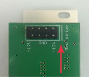
Most modules will come with the cable already connected but it is good to double-check the orientation. Be aware that some modules may have headers that serve other purposes so ensure the power cable is connected to the right one.
The other end of the cable, with a 16-pin connector, connects to the power bus board of your Eurorack case. Ensure the red stripe on the cable lines up with the -12V pins on the bus board. On Intellijel power supplies the pins are labeled with the label “-12V” and a thick white stripe. Sometimes the connectors are shrouded, ensuring the cable can only be oriented in one direction. If you are using another manufacturer’s power supply, check their documentation for instructions.Once connected, the cabling between the module and power supply should resemble the picture below:
Before reconnecting power and turning on your modular system, double-check that the ribbon cable is fully seated on both ends and that all the pins are correctly aligned. If the pins are misaligned in any direction or the ribbon is backward you can cause damage to your module, power supply, or other modules.After you have confirmed all the connections, you can reconnect the power cable and turn on your modular system. You should immediately check that all your modules have powered on and are functioning correctly. If you notice any anomalies, turn your system off right away and check your cabling again for mistakes.
OVERVIEW
Bifold is a dual-channel wave folder, where one channel (the P channel) has a sonic characteristic inspired by the Buchla-style Parallel “Deadband” folding circuit, while the other channel (the S channel) is more characteristic of a Serge-type Serial folding circuit.Besides offering two unique flavors of wave folding, Bifold features numerous feedback and routing options along with CV control, enabling you to mix, blend and crossfade those flavors into a rich stew of unique waveforms and harmonic movement.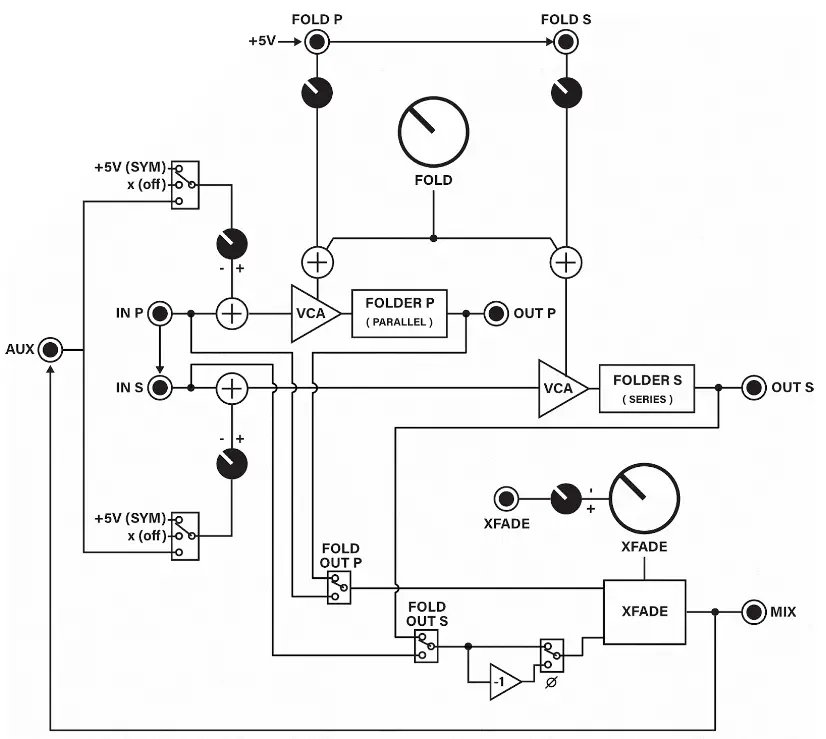
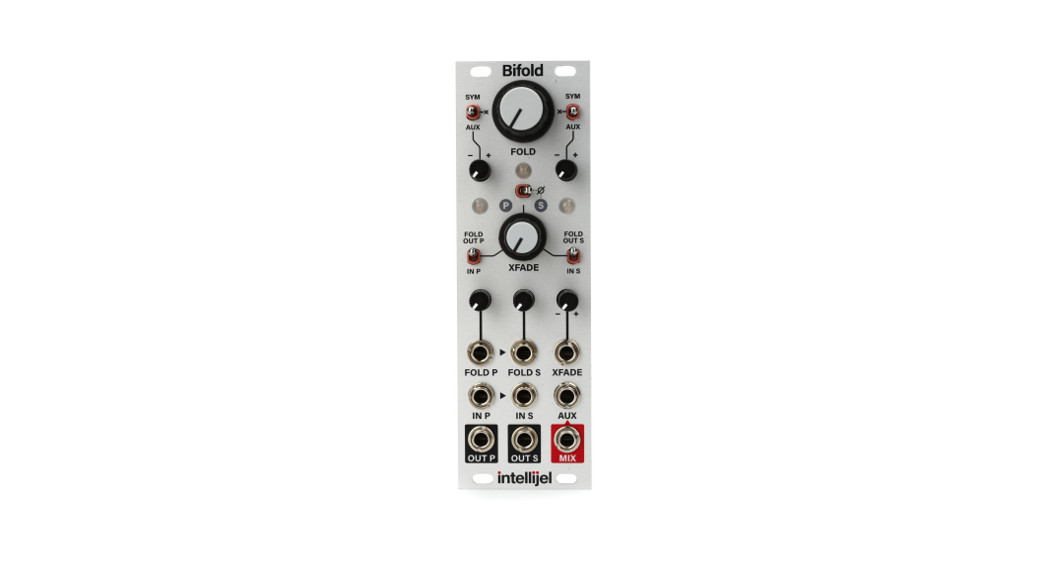
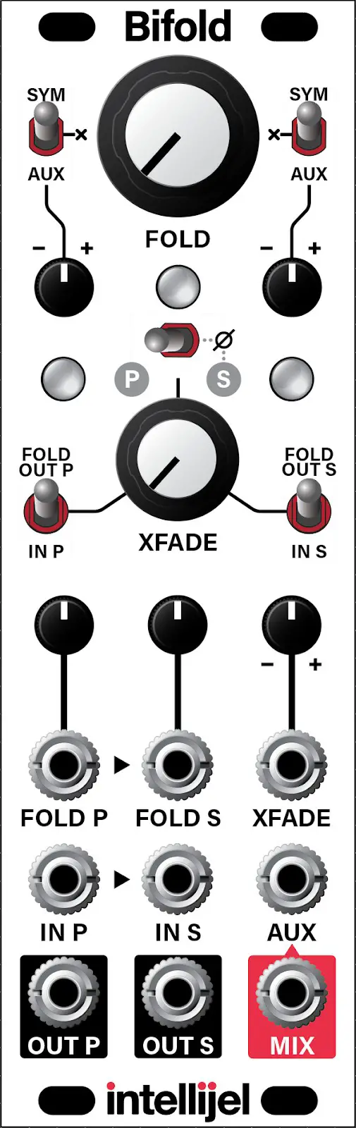
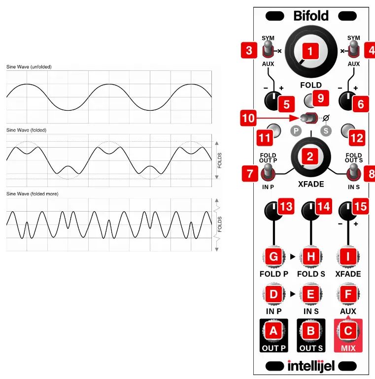
BIFOLD FRONT PANEL
Controls
- FOLD knob – This knob sets the initial amount of wave folding applied to both the IN P [D] (parallel) and IN S [E] (serial) folders and sent to the OUT P [A], OUTS [B], and MIX [C] outputs.
 Any modulation applied to the FOLD P [G] or FOLD S [H] CV inputs varies the amount of folding around the value set by the FOLD knob, with positive CV increasing the amount of folding applied by the respective ( P or S ) circuit, and negative values decreasing it.NOTE: When set fully counterclockwise, no signal appears at any of the outputs unless CV is applied to the FOLD P [G] or FOLD S [H] CV input and/or their respective attenuators [13, 14] are turned up (i.e. NOT fully counterclockwise).
 - XFADE knob – Controls the relative mix of the two folders present at the MIX [C] output. When fully counterclockwise, only the Parallel circuitry is heard at the MIX out. Turning the XFADE knob clockwise crossfades from the Parallel folder to the Serial folder, with both circuits feeding equal signals into the MIX output at the noon position. When fully clockwise, only the Serial circuity is heard at the MIX out.You can choose whether to feed the crossfader with either channel’s unfolded (dry) signal ( IN P [D] or IN S [E] ) or with its folded signal. This is accomplished with the XFADE P [7] and XFADE S [8] input select switches and enables you to blend a folded signal with a dry signal for more sonic diversity.
- SYM-X-AUX switch for Parallel Folder – The position of this switch affects the signal being fed into the Parallel folder. Specifically:SYM – When set to SYM (up position) a DC offset of up to ±5V is added to the IN P [D] value, which affects the symmetry of the wave folding. The amount of offset (and asymmetry) is controlled by the corresponding attenuverter knob [5].AUX – When set to AUX (down position), the AUX [F] input is added to the IN P [D] signal (after being attenuated by the corresponding knob [5] ). Note that if nothing is connected to the AUX [F] jack, then the signal appearing at the MIX [C] output is used as the AUX input.X – When set to X (middle position), no external voltages are added to the IN P [D] value, so the input to the P arallel folder is symmetrical and unmodulated by any external input.
- SYM-X-AUX switch for Serial Folder – The position of this switch affects the signal being fed into the S erial folder. Specifically:SYM – When set to SYM (up position) a DC offset of up to ±5V is added to the IN S [E] value, which affects the symmetry of the wavefolding (shown in the illustration on the previous page). The amount of offset (and asymmetry) is controlled by the corresponding attenuverter knob [6].AUX – When set to AUX (down position), the AUX [F] input is added to the IN S [E] signal (after being attenuverted by the corresponding knob [6] ).Note that if nothing is connected to the AUX [F] jack, then the signal appearing at the MIX [C] output is used as the AUX input.X – When set to X (middle position), no external voltages are added to the IN S [E] value, so the input to the Serial folder is symmetrical and unmodulated by any external input.
- SYM-AUX attenuverter for Parallel Folder – Depending on the setting of the Parallel folder’s SYM-X-AUX switch [3], the knob either anteverts a 5V DC offset voltage (when set to the “SYM” position) or it attenuverts the AUX [F] input voltage (when set to the “AUX” position). It has no effect when the corresponding SYM-X-AUX switch is set to the “X” position.
- SYM-AUX attenuverter for Serial Folder – Depending on the setting of the Serial folder’s SYM-X-AUX switch [4], the knob either attenuverts a 5V DC offset voltage (when set to the “SYM” position) or it attenuverts the AUX [F] input voltage (when set to the “AUX” position). It has no effect when the corresponding SYM-X-AUX switch is set to the “X” position.
- XFADE P input selector switch – The position of this switch selects the signal source that feeds into the crossfader’s P -side input (counterclockwise rotation of the XFADE [2] knob), which is then mixed with the selected S -side input and sent through to the MIX [C] output.FOLD OUT P (up position) – the output of the Parallel folder ( OUT P [A] ) feeds the P -side (counterclockwise) input of the XFADE circuit.IN P (down position) – the input of the Parallel folder ( IN P [D] ) feeds the P -side (counterclockwise) input of the XFADE circuit. This is particularly useful if you want to mix a folded signal with a dry signal, making the XFADE [2] knob function as a sort of wet/dry control.
- XFADE S input selector switch – The position of this switch selects the signal source that feeds into the crossfader’s S -side input (clockwise rotation of the XFADE [2] knob), which is then mixed with the selected P -side input and sent through to the MIX [C] output.FOLD OUTS (up position) – the output of the Serial folder ( OUT S [B] ) feeds the S -side (clockwise) input of the XFADE circuit.IN S (down position) – the input of the S erial folder ( IN S [E] ) feeds the S -side (clockwise) input of the XFADE circuit. This is particularly useful if you want to mix a folded signal with a dry signal, making the XFADE [2] knob function as a sort of wet/dry control.
- MIX LED – Indicates presence of signal at MIX [C] output. The brightness of the LED indicates the amount of signal present (the brighter the LED, the louder the output). The color of the LED indicates the polarity, with red=negative and green=positive. At audio rates, the colors oscillate so fast that the LEDs will basically appear orange.
- PHASE switch – Inverts the phase of the Serial folder that feeds the XFADE circuit, which can change the sonic attributes at the MIX [C] output, as well as allow for ring modulation (discussed in the Ring Modulator section, later in the manual).
- OUT P LED – Indicates presence of signal at OUT P [A]. The brightness of the LED indicates the amount of signal present (the brighter the LED, the louder the output). The color of the LED indicates the polarity, with red=negative and green=positive. At audio rates, the colors oscillate so fast that the LEDs will basically appear orange.
- OUT S LED – Indicates presence of signal at OUT S [B]. The brightness of the LED indicates the amount of signal present (the brighter the LED, the louder the output). The color of the LED indicates the polarity, with red=negative and green=positive. At audio rates, the colors oscillate so fast that the LEDs will basically appear orange.
- FOLD P attenuator – This knob attenuates the voltage patched into the FOLD P [G] CV input jack.When set fully clockwise, all the voltage appearing at FOLD P is used to control the amount of folding sent to the Parallel folder.When set fully counterclockwise, the input CV is fully attenuated, and none of the FOLD P voltage is used to control folding.NOTE: If nothing is plugged into the FOLD P [G] jack, then Bifold internally normals +5V to that jack, meaning this knob acts as a 0V (counterclockwise) to +5V(clockwise) attenuator.IMPORTANT: If the FOLD [1] knob is set fully counterclockwise and nothing is connected to the FOLD P [G] CV input, then you must set the attenuator knob to some value above 0 (fully counterclockwise) in order to hear any output.
- FOLD S attenuator – This knob attenuates the voltage patched into the FOLD S [H] CV input jack. It works exactly like the FOLD P [13] attenuator knob (described above), but governs the Serial folder circuit instead.
- XFADE attenuverter – This knob attenuverts the voltage patched into the XFADE [I] CV input jack.When set fully clockwise, all the voltage appearing at the XFADE [I] jack is used to control the amount of crossfading. When set fully counterclockwise, the full inverse value of the control voltage is used. When set at the noon position, the XFADE input CV is fully attenuated, and does not affect the XFADE amount.
 Any modulation applied to the FOLD P [G] or FOLD S [H] CV inputs varies the amount of folding around the value set by the FOLD knob, with positive CV increasing the amount of folding applied by the respective ( P or S ) circuit, and negative values decreasing it.NOTE: When set fully counterclockwise, no signal appears at any of the outputs unless CV is applied to the FOLD P [G] or FOLD S [H] CV input and/or their respective attenuators [13, 14] are turned up (i.e. NOT fully counterclockwise).
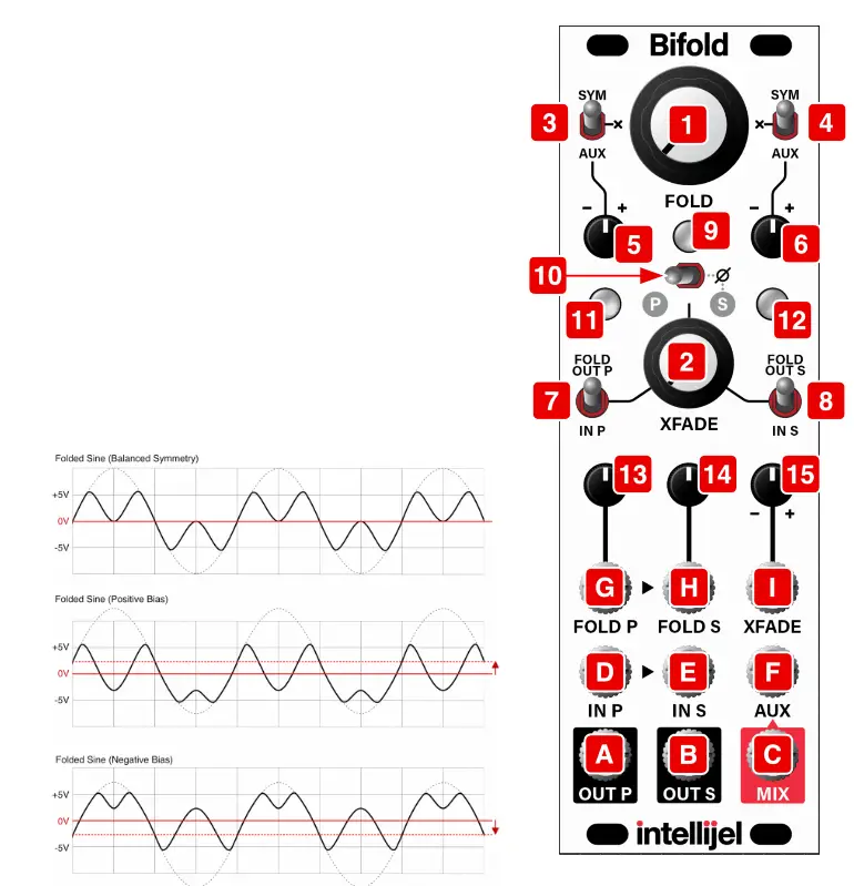 AUX – When set to AUX (down position), the AUX [F] input is added to the IN P [D] signal (after being attenuated by the corresponding knob [5] ). Note that if nothing is connected to the AUX [F] jack, then the signal appearing at the MIX [C] output is used as the AUX input.X – When set to X (middle position), no external voltages are added to the IN P [D] value, so the input to the P arallel folder is symmetrical and unmodulated by any external input.
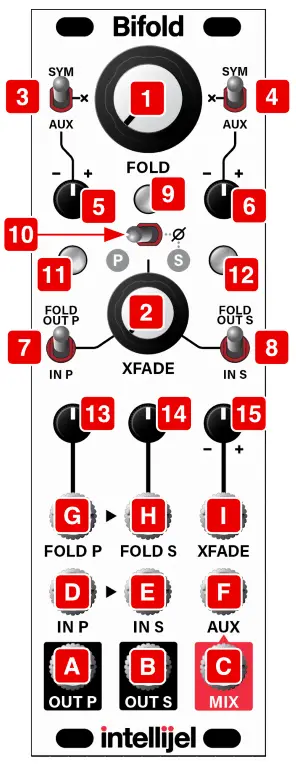 SYM – When set to SYM (up position) a DC offset of up to ±5V is added to the IN S [E] value, which affects the symmetry of the wavefolding (shown in the illustration on the previous page). The amount of offset (and asymmetry) is controlled by the corresponding attenuverter knob [6].AUX – When set to AUX (down position), the AUX [F] input is added to the IN S [E] signal (after being attenuverted by the corresponding knob [6] ).Note that if nothing is connected to the AUX [F] jack, then the signal appearing at the MIX [C] output is used as the AUX input.X – When set to X (middle position), no external voltages are added to the IN S [E] value, so the input to the Serial folder is symmetrical and unmodulated by any external input.
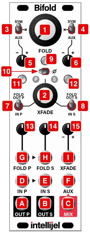

Inputs and Outputs
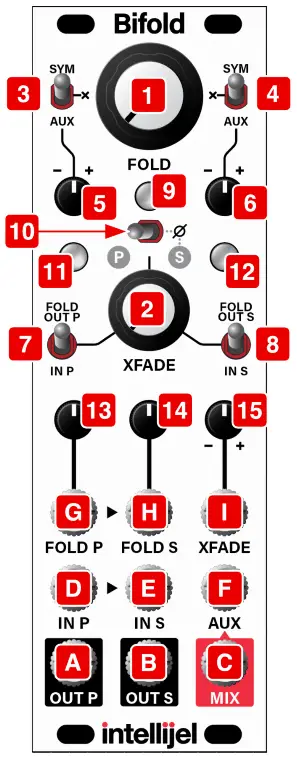
[A] OUT P – Output of the P arallel wavefolder circuit.[B] OUT S – Output of the Serial wavefolder circuit.[C] MIX OUT – Output of the mixed (crossfaded) Parallel and Serial folder circuits.[D] IN P – Input to the P (parallel) wavefolder circuit. This circuit is a Buchla-inspired parallel “deadband” folder.The signal sent here is folded by an amount set by the FOLD [1] knob and the FOLD P [G] CV input and its corresponding attenuator [13]. Folding is further modified by the position of the Parallel folder’s SYM-X-AUX [3] switch and its corresponding attenuverter [5] .The folded output appears at the OUT P [A] jack, and can also be mixed and crossfaded with the Serial folder, with the combined output sent to the MIX [C] output jack.
[E] IN S – Input to the S (serial) wavefolder circuit. This circuit is a Serge-inspired serial folder. If no jack is inserted into IN S, then the signal at IN P [D] also feeds the Serial circuit.The signal sent here is folded by an amount set by the FOLD [1] knob and the FOLD S [H] CV input and its corresponding attenuator [14]. Folding is further modified by the position of the Serial folder’s SYM-X-AUX [4] switch and its corresponding attenuverter [6] .
The folded output appears at the OUT S [B] jack, and can also be mixed and crossfaded with the Parallel folder, with the combined output sent to the MIX [C] output jack.
[F] AUX IN – If either of the SYM-X-AUX switches [3, 4] is set to the AUX position, then the signal received by this jack is added to the signal that’s sent to the corresponding P arallel or Serial folding circuit. The amount and polarity of added AUX signal is determined by the position of its associated SYM-AUX attenuverter [5, 6].If nothing is patched into the AUX input, then Bifold’s MIX [C] output feeds the AUX input.
[G] FOLD P CV IN – This input accepts a ±10V control voltage for externally controlling the amount of folding applied to the Parallel wavefolder.The control voltage modulates the amount of initial folding as set by the FOLD [1] knob, and is attenuated by the corresponding FOLD P [13] attenuator knob. Positive voltages increase the amount of folding above the value set by the FOLD [1] knob; negative voltages decrease it.
When the FOLD [1] knob is fully counterclockwise, sending 0V – 5V to the FOLD P [G] jack governs the folding (though a little ‘extra’ folding is available with up to 10V of CV input). When the FOLD [1] knob is higher than its minimum position, then negative voltages applied to FOLD P decrease the folding, and positive voltages increase it.If nothing is plugged into this jack, then +5V is internally applied, which can be attenuated using the corresponding FOLD P [13] attenuator knob.
[H] FOLD S CV IN – This input accepts a ±10V control voltage for externally controlling the amount of folding applied to the Serial wavefolder. This circuit is a Serge-inspired serial folder. If no jack is inserted into FOLD S, then the signal at FOLD P [G] also feeds the CV input for the Serial folder.The control voltage modulates the amount of initial folding as set by the FOLD [1] knob, and is attenuated by the corresponding FOLD S [14] attenuator knob. Positive voltages increase the amount of folding above the value set by the FOLD [1] knob; negative voltages decrease it.When the FOLD [1] knob is fully counterclockwise, sending 0V – 5V to the FOLD S [H] jack governs the folding (though a little ‘extra’ folding is available with up to 10V of CV input). When the FOLD [1] knob is higher than its minimum position, then negative voltages applied to FOLD S decrease the folding, and positive voltages increase it.
If nothing is plugged into either this jack or the FOLD P [G] jack, then +5V is internally applied, which can be attenuated using the corresponding FOLD S [14] attenuator knob.
[I] XFADE CV IN – This input accepts a ±5V control voltage for externally controlling the amount of crossfading between the Parallel and Serial folders, as heard from the MIX [C] output. The input voltage can be attenuverted using the corresponding XFADE attenuverter [16].
The control voltage modulates the amount of initial crossfading as set by the XFADE [2] knob, and is attenuverted by the corresponding XFADE [15] attenuverter knob. When the value of the XFADE [2] knob and the attenuverted XFADE [I] inputs sums to zero (or a negative voltage), then only the Parallel channel feels the crossfader. When the value of the XFADE [2] knob and the attenuverted XFADE [I] inputs sums to +5V, then only the Serial channel feels the crossfader. Summed voltages between 0V and 5V create a blend of the two channels.
USAGE SCENARIOS
Aside from such obvious applications as 1) two totally independent wavefolders, or 2) a single two-folder circuit with variable series/parallel routings, there are several other sonically interesting usage scenarios, as outlined in the following sections.
Crossfading Folded and Unfolded Waveforms
You can use Bifold to mix together two different waveforms from a single (or multiple) oscillators — one folded and one unfolded — then crossfade between them to create complex and evolving waveforms. To do so:
- Patch the MIX [C] output into your audio system.
- Set the XFADE knob [2] fully counter-clockwise (toward “P”).
- Send a sine wave (or any other waveform) into IN P [D] .
- Set the XFADE P [7] input selector switch to the “FOLD OUT P” (up) position.
- Set the XFADE S [8] input selector switch to the “IN S” (down) position.
- Flip the PHASE [10] switch to the left, putting the two folders in-phase with one another.
- Send one of the oscillator’s other waveforms (such as a triangle) into IN S [E] .
- Rotate the FOLD [1] knob to dial in the desired amount of wavefolding.Because the XFADE knob [2] is set fully counter-clockwise, only the P -side input (a folded sine) is heard in the MIX [C] output.NOTE: if nothing is patched into the FOLD P [G] input, then you will not hear any output until you start to fold the waveform using either the FOLD [1] knob or by turning the FOLD P [13] attenuator to any position other than fully counterclockwise.
- Rotate the XFADE [2] knob fully clockwise to hear only the S -side input (an unmodified triangle wave, in this example).
- Adjust the XFADE [2] knob to set the balance between folded and unfolded waves, and adjust the FOLD [1] knob to dial in the desired amount of folding.You can modulate both the XFADE and FOLD amounts using the FOLD P [G] and XFADE [I] CV inputs, along with their respective attenuators.
Stereo Folding
Some very interesting stereo effects can be achieved by sending OUT P [A] to one stereo channel, and the OUT S [B] jack to the other. For example:
- Patch a waveform into the IN P [D] jack and leave the IN S [E] jack unpatched. By default, IN S is normalled to IN P if nothing is connected to it.
- For now, set both folders’ SYM-X-AUX switches [3, 4] to the middle “X” position.
- Patch OUT P [A] to the left channel of your stereo monitoring system and OUT S [B] to the right channel.
- Set the FOLD P [13] and FOLD S [14] attenuators to their minimum values (fully counterclockwise).Note that, if the FOLD [1] knob is also fully counterclockwise, no signal will appear at the outputs.
- Slowly rotate the FOLD [1] knob to increase (clockwise) or decrease (counterclockwise) the amount of folding, creating an interesting stereo effect since the two fold circuits have different sonic characteristics.
- Set the FOLD P [13] and FOLD S [14] knobs to offset the amount of folding applied by each channel.
- Try different SYM-X-AUX [3, 4] switch positions and vary the corresponding parameters to add further variation between channels.
- Try sending a control voltage into FOLD P [G], and varying the amount of attenuation using both the FOLD P [13] and FOLD S [14] attenuator knobs.Or, for real chaos, send different control voltages into FOLD P [G] and FOLD S [H].
Ring Modulation
 report this ad
You can use the Bifold as a ring modulator, as follows:
- Set both the Parallel and Serial SYM-X-AUX switches [3, 4] to the middle “X” position.
- Set both the XFADE P [7] and the XFADE S [8] input selector switches to their down positions.
- Flip the PHASE [10] switch to the right, putting the S -side out of phase with the P -side.
- Patch an oscillator into IN P [D] , and monitor the MIX [C] output.
- Rotate the XFADE knob [2] until you hear no sound from the MIX [C] output.The knob will be approximately straight up.
- Patch a second oscillator into the XFADE [I] CV input and set the XFADE [15] attenuverter fully positive (clockwise).The oscillator plugged into IN P [D] is ring modulated by the oscillator plugged into the XFADE [I] input, and sent to the MIX [C] output.
Amplitude Modulation
You can also use the Bifold to create Amplitude Modulation (AM). To do so:
- Follow steps 1-6 in the Ring Modulation description, above.
- Plug a dummy cable into IN S [E] .
- The waveform patched to XFADE [I] input is now amplitude modulating the waveform patched into IN P [D] .
Random Noise Generation
Use the module’s built-in feedback path to create all manner of strange and chaotic blips, hisses and noise bursts. To do so:
- Unpatch everything except the MIX [C] output.
- Set both the Parallel and Serial SYM-X-AUX switches [3, 4] to the AUX (bottom) position.
- Set each channel’s SYM-AUX attenuverter [5, 6] to a value other than null (i.e., not straight up).
- Set the Fold P [13] and Fold S [14] attenuators to some value greater than minimum (i.e., not fully counterclockwise).
- Set both the XFADE P [7] and the XFADE S [8] input selector switches to their up (FOLD OUT P, FOLD OUT S) positions.
- Twiddle the FOLD [1] and XFADE [2] knobs, as well as the two SYM-AUX attenuverters while listening to the feedback noise being sent from the MIX [C] output.Enjoy the squeaks, clicks, squawks, and hissing variants of noise that result.
TECHNICAL SPECIFICATIONS
| Bifold | |
| Width | 8 hp |
| Maximum Depth | 38 mm |
| Current Draw | 94 mA @ +12V94 mA @ -12V |
References
[xyz-ips snippet=”download-snippet”]