intellijel Dixie II+ Full-Featured Triangle Core Analog VCO/LFO
COMPLIANCE
This device complies with Part 15 of the FCC Rules. Operation is subject to the following two conditions: (1) this device may not cause harmful interference, and (2) this device must accept any interference received, including interference that may cause undesired operation.Changes or modifications not expressly approved by Intellijel Designs, Inc. could void the user’s authority to operate the equipment.Any digital equipment has been tested and found to comply with the limits for a Class A digital device, pursuant to part 15 of the FCC Rules. These limits are designed to provide reasonable protection against harmful interference when the equipment is operated in a commercial environment. This equipment generates, uses, and can radiate radio frequency energy and, if not installed and used in accordance with the instruction manual, may cause harmful interference to radio communications.
 This device meets the requirements of the following standards and directives:
EMC: 2014/30/EUEN55032:2015 ; EN55103-2:2009 (EN55024) ; EN61000-3-2 ; EN61000-3-3
Low Voltage: 2014/35/EUEN 60065:2002+A1:2006+A11:2008+A2:2010+A12:2011
RoHS2: 2011/65/EUWEEE: 2012/19/EU
INSTALLATION
Intellijel Eurorack modules are designed to be used with a Eurorack-compatible case and power supply. We recommend you use Intellijel cases and power supplies.Before installing a new module in your case, you must ensure your power supply has a free power header and sufficient available capacity to power the module:
- Sum up the specified +12V current draw for all modules, including the new one. Do the same for the -12 V and +5V current draw. The current draw will be specified in the manufacturer’s technical specifications for each module.
- Compare each of the sums to specifications for your case’s power supply.
- Only proceed with installation if none of the values exceeds the power supply’s specifications. Otherwise you must remove modules to free up capacity or upgrade your power supply.
You will also need to ensure your case has enough free space (hp) to fit the new module. To prevent screws or other debris from falling into the case and shorting any electrical contacts, not leave gaps between adjacent modules, and cover all unused areas with blank panels. Similarly, do not use open frames or any other enclosure that exposes the backside of any module or the power distribution board.
You can use a tool like Modular Grid to assist in your planning. Failure to adequately power your modules may result in damage to your modules or power supply. If you are unsure, please contact us before proceeding.
Installing Your Module
When installing or removing a module from your case always turn off the power to the case and disconnect the power cable. Failure to do so may result in serious injury or equipment damage.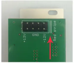 Ensure the 10-pin connector on the power cable is connected correctly to the module before proceeding. The red stripe on the cable must line up with the -12V pins on the module’s power connector. The pins are indicated with the label -12V, a white stripe next to the connector, the words “red stripe”, or some combination of those indicators.
Most modules will come with the cable already connected but it is good to double check the orientation. Be aware that some modules may have headers that serve other purposes so ensure the cable is connected to the right one.
The other end of the cable, with a 16-pin connector, connects to the power bus board of your Eurorack case. Ensure the red stripe on the cable lines up with the -12V pins on the bus board. On Intellijel power supplies the pins are labelled with the label “-12V” and a thick white stripe:
If you are using another manufacturer’s power supply, check their documentation for instructions.
Once connected, the cabling between the module and power supply should resemble the picture below:Before reconnecting power and turning on your modular system, double check that the ribbon cable is fully seated on both ends and that all the pins are correctly aligned. If the pins are misaligned in any direction or the ribbon is backwards you can cause damage to your module, power supply, or other modules.
After you have confirmed all the connections, you can reconnect the power cable and turn on your modular system. You should immediately check that all your modules have powered on and are functioning correctly. If you notice any anomalies, turn your system off right away and check your cabling again for mistakes.
OVERVIEW
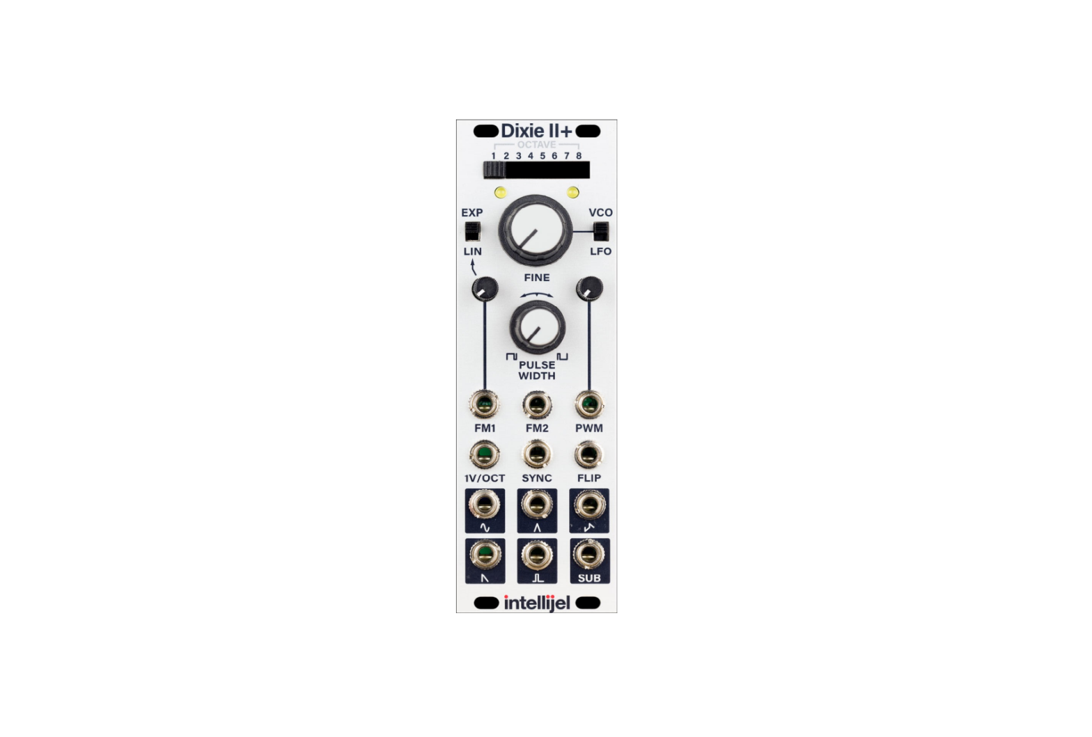
The Dixie II+ is a fully analogue triangle-core oscillator capable of generating five different waveforms plus a square wave sub-oscillator.
Front Panel
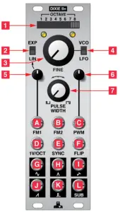
Controls
[1] OCTAVE – This 8-position switch is used to set the coarse tuning of the oscillator. Each position shifts the tuning by one octave. Fine adjustment can be made using the FINE knob. Note that when in LFO and with the FINE knob turned up the oscillator may hit the upper limits of the LFO frequency range when the switch is in the higher octave settings.
[2] EXP/LIN – This switch selects the mode of the FM1 input between linear and exponential response.
[3] FINE – When in VCO mode this knob functions as a fine adjustment for the tuning frequency. The range is approximately +/- 6 semitones from the centre position. When the oscillator is in LFO mode the range of the knob is much higher, approximate +/- 7 octaves.
[4] VCO/LFO – This switch switches the Dixie II+ between VCO and LFO mode. When in VCO mode the oscillator operates at audio rates with frequencies between 20 Hz up to almost 60 kHz. When in LFO mode the it can achieve cycles from several minutes in length up to low audio rates of around 1 kHz.
[5] FM1 Attenuator – Attenuator for the FM1 input.
[6] PWM Attenuator – Attenuator for the PWM input.
[7] PULSE WIDTH – This knob sets the base pulse width of the PULSE output. When fully counter clockwise the output will produce a narrow 10% duty cycle pulse, when fully clockwise it produces a pulse with a 90% duty cycle. A square wave is produced with the knob in the 12 o’clock position. The knob is summed with the PWM input.
Inputs & Outputs
[A] FM 1 – Linear or exponential frequency modulation input. The behaviour is set by the LIN/EXP switch.
[B] FM 2 – Exponential frequency modulation input.
[C] PWM – This input is summed with the PULSE WIDTH knob to set the width of the PULSE output. The range is +/- 5 V. Note that the width can go down to 0% and up to 100% at which point no wave will be produced.
[D] 1V/OCT – Primary pitch voltage control input.
[E] SYNC – When the input waveform crosses zero the oscillator is also reset to zero.
[F] FLIP – This input functions similarly to the SYNC input except that instead of resetting the oscillator to zero it flips the direction of travel.
[G] SINE – Sine wave output.
[H] TRIANGLE – Triangle wave output.
[I] ZIG-ZAG – Zig-zag wave output.
[J] SAW – Saw wave output.
[K] PULSE – Pulse wave output. The width of the pulse is controlled by a combination of the PULSE WIDTH knob and PWM input.
[L] SUB – Sub-oscillator output. Produces a 50% duty cycle square wave with a frequency one octave below that of the primary oscillator.
TECHNICAL SPECIFICATIONS
| Width | 8 hp |
| Maximum Depth | 40 mm |
| Current Draw | 60 mA @ +12V70 mA @ -12V |
report this ad
References
[xyz-ips snippet=”download-snippet”]