intellijel Morgasmatron
COMPLIANCE
This device complies with Part 15 of the FCC Rules. Operation is subject to the following two conditions: (1) this device may not cause harmful interference, and (2) this device must accept any interference received, including interference that may cause undesired operation.Changes or modifications not expressly approved by Intellijel Designs, Inc. could void the user’s authority to operate the equipment.Any digital equipment has been tested and found to comply with the limits for a Class A digital device, pursuant to part 15 of the FCC Rules. These limits are designed to provide reasonable protection against harmful interference when the equipment is operated in a commercial environment. This equipment generates, uses, and can radiate radio frequency energy and, if not installed and used in accordance with the instruction manual, may cause harmful interference to radio communications.
This device meets the requirements of the following standards and directives:EMC: 2014/30/EUEN55032:2015 ; EN55103-2:2009 (EN55024) ; EN61000-3-2 ; EN61000-3-3Low Voltage: 2014/35/EUEN 60065:2002+A1:2006+A11:2008+A2:2010+A12:2011RoHS2: 2011/65/EUWEEE: 2012/19/EU
INSTALLATION
Intellijel Eurorack modules are designed to be used with a Eurorack-compatible case and power supply. We recommend you use Intellijel cases and power supplies.Before installing a new module in your case, you must ensure your power supply has a free power header and sufficient available capacity to power the module:
- Sum up the specified +12V current draw for all modules, including the new one. Do the same for the -12 V and +5V current draw. The current draw will be specified in the manufacturer’s technical specifications for each module.
- Compare each of the sums to specifications for your case’s power supply.
- Only proceed with installation if none of the values exceeds the power supply’s specifications. Otherwise, you must remove modules to free up capacity or upgrade your power supply.
You will also need to ensure your case has enough free space (hp) to fit the new module. To prevent screws or other debris from falling into the case and shorting any electrical contacts, do not leave gaps between adjacent modules, and cover all unused areas with blank panels. Similarly, do not use open frames or any other enclosure that exposes the backside of any module or the power distribution board.You can use a tool like ModularGrid to assist in your planning. Failure to adequately power your modules may result in damage to your modules or power supply. If you are unsure, please contact us before proceeding.
Installing Your Module

When installing or removing a module from your case always turn off the power to the case and disconnect the power cable. Failure to do so may result in serious injury or equipment damage.Ensure the 10-pin connector on the power cable is connected correctly to the module before proceeding. The red stripe on the cable must line up with the -12V pins on the module’s power connector. The pins are indicated with the label -12V, a white stripe next to the connector, the words “red stripe”, or some combination of those indicators.Most modules will come with the cable already connected but it is good to double check the orientation. Be aware that some modules may have headers that serve other purposes so ensure the cable is connected to the right one.The other end of the cable, with a 16-pin connector, connects to the power bus board of your Eurorack case. Ensure the red stripe on the cable lines up with the -12V pins on the bus board. On Intellijel power supplies the pins are labelled with the label “-12V” and a thick white stripe:If you are using another manufacturer’s power supply, check their documentation for instructions.
Once connected, the cabling between the module and power supply should resemble the picture below:
Before reconnecting power and turning on your modular system, double check that the ribbon cable is fully seated on both ends and that all the pins are correctly aligned. If the pins are misaligned in any direction or the ribbon is backwards you can cause damage to your module, power supply, or other modules.After you have confirmed all the connections, you can reconnect the power cable and turn on your modular system. You should immediately check that all your modules have powered on and are functioning correctly. If you notice any anomalies, turn your system off right away and check your cabling again for mistakes.
OVERVIEW
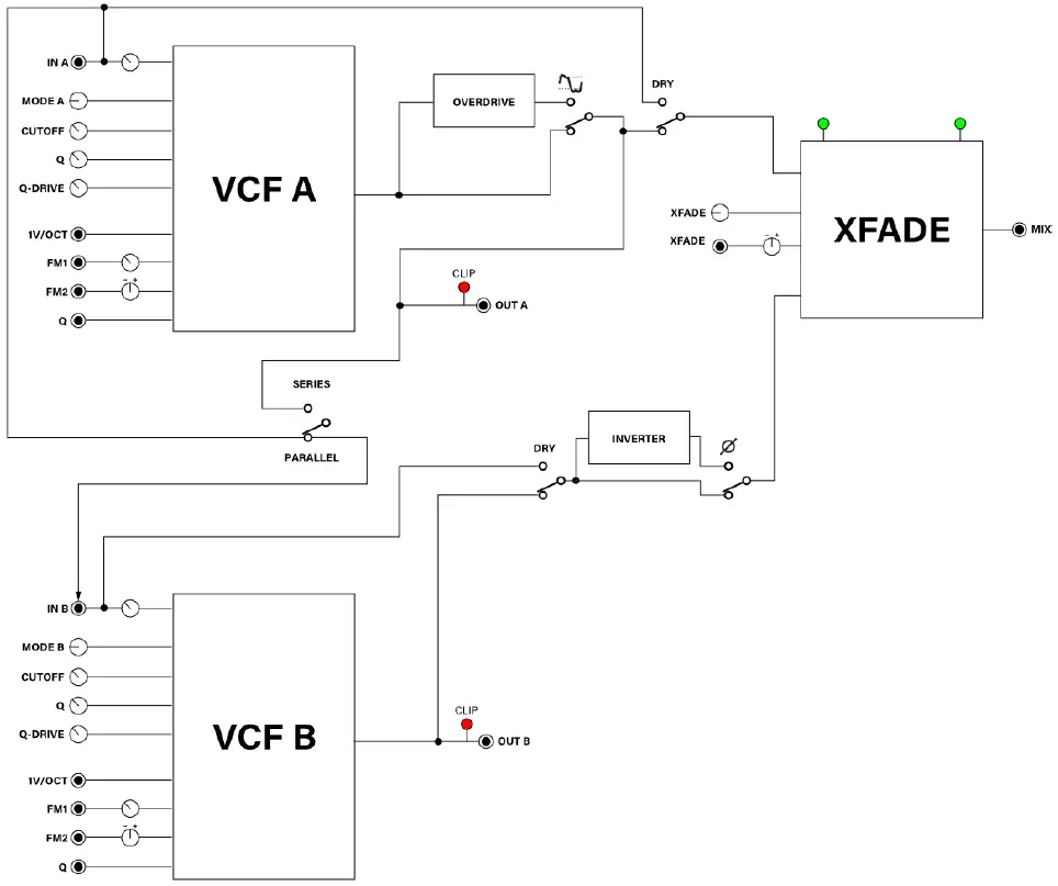
This is the third generation of Intellijel’s legendary Korgasmatron filter designed in collaboration with David G. Dixon. For obvious reasons, we considered naming it the Korgasmatron III. But once we experienced the purity and range of its finely re-tuned filters; the warmth of its soft-clipping; the beefiness of its Q-drive; the aggressive howl of its all new overdrive circuit; the additional Xfade options; and its clangorous new ring modulation capabilities, we knew it was something much more than a Korgasmatron III. It was a MORgasmatron!The Morgasmatron features two completely independent six-mode filters (labeled “A” and “B”) — each with its own mode-select knob, input, output, cutoff, resonance, Q-drive and gain control. Each filter has a pair of CV inputs (one with a built-in attenuator and the other with a built-in attenuverter) for modulating cutoff, and another CV input for modulating resonance. Both filters self-oscillate at maximum Q, and produce pitched sine waves that track the two separate 1V/OCT inputs.You can use the two filters independently of one another, or you can use them together (in either a series or parallel connection) and smoothly crossfade between them using either the XFADE knob or the XFADE CV input and built-in attenuverter. You can flip the DRY switches to instantly bypass either or both filters; invert the phase of Filter B; or overdrive Filter A by switching on the new Overdrive circuit. A MIX output provides (as you might suspect) a mixed output of the two filters.
FRONT PANEL
Controls for Filters A & B The following controls are identical for both Filter A (left side, labeled in red ) and Filter B (right side, labeled in blue ):
- CUTOFF – Sets the cutoff frequency of the filter. The knob position is combined with the FM1 and FM2 inputs.
- FM1 – Controls the amount of attenuation for the FM1 input.Although the FM1 input tracks 1V/Oct when this knob is fully clockwise, each filter features a dedicated 1V/Oct input. This means you’re free to use FM1 for more creative modulation duties, while using the dedicated 1V/OCT input for tracking pitch.
- FM2 – Controls the amount and polarity of the FM2 input. The FM input has maximum positive effect when the knob is fully clockwise; maximum inverted effect when fully counter-clockwise; and no effect when at the 12 o’clock position.
- MODE – This knob cycles between the different Morgasmatron filter modes. The modes are LP2 (2-pole lowpass), LP1 (1-pole lowpass), BP1 (1-pole bandpass), HP1 (1-pole highpass), HP2 (2-pole highpass), and BR1 (1-pole band reject, or ‘ notch’).
- Q – Sets the resonance of the filter. The knob position is combined with the Q input.
- Q-DRIVE – Adds additional drive to the filter resonance. This keeps resonance levels high as the gain levels increase, while providing a warming “growl” at mid Q values.Resonance in the classic MS-20 filter reaches its maximum output at lower input volumes, which means — as you continue to add gain — you begin to drown out the resonance. To negate this effect, Morgasmatron feeds resonance back into the filter at an amount determined by the Q-DRIVE knob, thus preventing resonance from being “drowned out” at higher amplitudes.If Q is turned down, then Q-DRIVE will have no effect. You need to have some amount of resonance in order for Q-DRIVE to work.When a filter’s resonance is driven into self-oscillation, increasing the Q-DRIVE soft-clips the resulting sine wave, creating a slightly squared-off waveform with more harmonic content.

- OVERLOAD LED – Monitors the filter’s output, and begins to illuminate when the signal soft clips.
- IN – Sets the drive, or amplification, of the input signal. With a typical 10V p-p eurorack signal, unity gain is around 12 o’clock. As you turn the knob further clockwise (past 12 o’clock), you will increase the signal level and induce soft clipping.Controls for Filter Interaction The following controls change the way in which the two filters interact, are routed to the crossfader or provide features unique to either Filter A or Filter B, and are thus located in the middle of the panel and labeled in green in the previous diagram:
- OVERDRIVE – Turn this on (switch in the up position) to activate the overdrive circuit for Filter A. Overdrive provides a more aggressively saturated distortion than you can obtain by simply boosting the Input or Q- Drive.With overdrive turned off (switch in down position), the output of Filter A is “clean” (with the exception of any soft-clipping induced by either a high IN level or Q-Drive).
- DRY SWITCH A – Switch this to the Dry (up) position to remove the effect of Filter A at the XFADE input, meaning the Filter’s output is identical to its input.
- DRY SWITCH B – Switch this to the Dry (up) position to remove the effect of Filter B at the XFADE input, meaning the Filter’s output is identical to its input.Once you bypass a filter using its DRY switch, you can use the XFADE knob (in conjunction with the MIX out) to set a wet/dry mix between the processed and unprocessed signals. For example, if you turn on the OVERDRIVE circuit for Filter A and set Filter B to DRY, the XFADE knob acts a wet/dry control for distortion.
- PHASE INVERT – Switch this to the up position to invert the phase of Filter B signal being fed to the XFADE.The most obvious use of phase inversion is to create ring modulation (as described later in the manual), but you can also use it to create subtly different timbres when combining the two filters and monitoring the MIX output.
- XFADE – When monitoring the MIX output, this knobs sets the balance between the two filters. At 12 o’clock, Filters A and B are equally present at the MIX output. When the knob is set clockwise of 12 o’clock, the MIX out contains more of Filter B’s signal than Filter A’s. Counterclockwise of 12 o’clock the opposite is true — the MIX out contains more of Filter A’s signal than Filter B’s.
- XFADE BALANCE LED – Visual indication of the current XFADE amount. The brighter the LED on the left, the more Filter A feeds the MIX output; the brighter the LED on the right, the more Filter B feeds the MIX output.
- XFADE ATTENUVERTER – Reduces and/or inverses how much a signal appearing at the XFADE CV input jack modulates the XFADE. At 12 o’clock, the XFADE CV input has no effect on XFADE. Values clockwise of 12 o’clock increase the amount by which the XFADE CV input skews toward a greater mix of Filter B. Values counterclockwise of 12 o’clock increase the amount by which the XFADE CV input skews toward a greater mix of Filter A.
- SERIES / PARALLEL SWITCH – Switches between a Series connection when flipped up (causing the output of Filter A to feed the input of Filter B), and a parallel connection when flipped down (resulting in two totally independent filters processing the signal simultaneously).
Inputs & Outputs For Filters A & B
The following inputs and outputs are identical for both Filter A (left side, shown in red) and Filter B (right side, shown in blue):
[A] IN – Audio input to the filter.[B] Q – CV input for controlling the filter resonance (Q). Use an external attenuverter (such as an Intellijel Triatt or Quadratt 1U) if you wish to invert the modulation or reduce its effect on resonance.[C] OUT – Audio output of the filter.[D] 1V/OCT – Dedicated 1V/OCT CV input, which causes the filter cutoff to track a keyboard or sequencer’s pitch over several octaves. If using the filter as an oscillator (maximum Q), this input acts as the pitch input for the oscillator. Filter A’s 1V/OCT input is normalled to Filter B’s 1V/OCT input — allowing a single pitch CV to modulate both filters simultaneously if nothing is plugged into Filter B’s 1V/OCT j ack.[E] FM1 – First of two scalable CV inputs for controlling filter cutoff.The FM1 attenuator knob controls how deeply the cutoff frequency is modulated by the signal appearing at FM1.[F] FM2 – Second of two scalable CV inputs for controlling filter cutoff. Filter A’s FM2 input is normalled to Filter B’s FM2 input — allowing a single external CV to modulate both filters simultaneously if nothing is plugged into Filter B’s FM2 j ack. Use the FM2 attenuverter knob to control both how deeply the cutoff frequency is modulated by the signal appearing at FM2 and the polarity of that modulation.
Inputs & Outputs For Filters Interaction The following inputs and outputs relate to the interaction of the two filters, and are thus located in the middle of the panel and shown in green in the previous diagram:
[G] MIX OUT – Outputs a blend of Filter A and Filter B, with the relative amount of each determined by the position of the XFADE knob and its corresponding CV input.[H] XFADE CV – CV Input for controlling XFADE, which determines the relative amounts of Filter A and Filter B that appear at the MIX out jack. The value of the input CV passes through the XFADE Attenuverter, and is summed with the current position of the XFADE knob.
PATCH EXAMPLES
With two separate multimode filters that can also be combined and routed in either series or parallel, there’s a wealth of dual-filtering effects just a tweak away. Among them are the ability to independently filter two entirely separate audio sources; or to stack two same-mode filters together in series (to steepen the cutoff slope). Or perhaps you’d like to set up a filter sweep in which notch or bandpass filters move in contrary motion? Or maybe you’re into formant simulation, which uses a pair of bandpass filters (with their cutoffs set very close together), some parallel routing, and a bit of tasteful modulation to make your Morgasmatron ‘ talk.’ You’re limited only by your imagination, and we welcome you to experiment and find your own favorite settings and techniques.However, we would like to point out a few ways to use Morgasmatron that might not be as immediately obvious…
Dual Sine Wave Oscillator This technique takes advantage of Morgasmatron’s self-oscillating filters and its 1V/OCT inputs to turn your dual filter into a dual oscillator.
- Patch the Pitch CV output of a keyboard or sequencer into Morgasmatron’s 1V/OCT input on Filter A.
- Patch the Morgasmatron’s OUT A jack into your audio monitoring system.
- Turn off the OVERDRIVE switch for Filter A and set its Q-Drive to minimum (counterclockwise), then increase Q to its maximum value (clockwise).This causes Filter A to self-oscillate, and you should hear a sine wave coming from the OUT A jack.
- Adjust Filter A’s CUTOFF knob to tune the sine wave oscillator.
- Experiment with increasing Q-DRIVE (which will mostly just increase gain, up to a point where soft-clipping occurs). Switching on the OVERDRIVE circuit will have a more pronounced effect on the waveshape and its harmonic content.
Since Morgasmatron features two filters, you can follow a similar procedure for Filter B (though it doesn’t have an OVERDRIVE circuit) to create a second sine wave oscillator, which can track the same V/Oct source as Filter A (useful if you want to detune the two oscillators slightly for a fatter sound), or track an entirely different V/Oct source — allowing for true duophonic operation.
Synth Voice Since Morgasmatron feature two filters, you can use one as an oscillator and the second as a filter, thereby turning Morgasmatron into a stand-alone synth voice.
- Follow steps 1-5 in the Dual Sine Wave Oscillator section (above) to configure Morgasmatron’s Filter A to function as an oscillator.
- Set the SERIES / PARALLEL SWITCH to the up (Series) position, such that the output of Filter A feeds directly into Filter B.
- Remove the jack from OUT A (which is currently feeding into your audio monitoring system) and insert it into OUT B instead.You are now monitoring the output of Filter B, which is being fed by Filter A.
- Experiment with different MODE B filter settings, and play around with the Cutoff, Q, Q-Drive and I N B levels. Filter B is acting as a filter for the oscillator produced by Filter A.TIP: Using OVERDRIVE on Filter A is a great way to add additional harmonics for Filter B to act upon. Also, setting Filter A’s Q-DRIVE to high levels will also add some soft clipping and grit to the filter.
- If you don’t want Filter B to track your keyboard/sequencer pitch, simply insert a dummy plug into Filter B’s 1V/OCT input (which breaks the normalling to Filter A’s 1V/OCT input).
If you want the filter to only partially track your keyboard/sequencer pitch, you can mult the signal being sent to Filter A’s 1V/OCT input — sending full 1V/OCT to Filter A (to control oscillator pitch), while running the second mult’s output through an attenuator (like a Triatt or Quadratt) before feeding it into the 1V/OCT input of Filter B.
Ringmod Morgasmatron makes an outstanding Ring Modulator:
- Patch an audio signal into Morgasmatron’s I N A.
- Patch the Morgasmatron’s MIX output into your audio monitoring system.
- Set the Morgasmatron to Parallel mode ( Series/Parallel Switch in the down position).
- Bypass both filters by setting the DRY switch to the up position.
- Phase invert Filter B by setting its Phase switch to the up position.
- While sending audio into I N A, set the XFADE knob to the straight-up (noon) position. Tweak the setting of the XFADE knob until the MIX output is as silent as possible.Since the two filters are 180 degrees out of phase, they will cancel each other out when their levels are balanced.
- Route an audio signal (such as a simple sine wave) from an external oscillator into the Morgasmatron’s XFADE CV Input, and turn up the XFADE Attenuverter.
- Instant ring modulation!
Use this as a jumping off point for further exploration: change the pitch of the XMOD CV; change its waveform; switch the filters out of DRY mode, and experiment with applying different filter settings to the sum and difference frequencies. Let the sound be your guide…
Overdrive With Tone Control If you flip on the Overdrive circuit for Filter A, connect it in series with Filter B, and monitor the OUT B, then you can use Level B for controlling the distorted signal l evel and Filter B as a tone control for “taming” the aggression — modulating the tone over time or adjusting the overall amount of overdriven signal present in the mix.
- Patch an audio signal into Morgasmatron’s I N A.
- Patch the Morgasmatron’s OUT B into your audio monitoring system.
- Set the Morgasmatron to Series mode ( Series/Parallel Switch in the up position).
- Switch on the Overdrive circuit for Filter A, and select the Mode, Cutoff, Q, Q-Drive and I N A to achieve the sound you want at “maximum” aggression.
- Play with Filter B’s Mode type and Cutoff frequency and make note of how it “tames” the distortion coming out of Filter A.
- Modulate Filter B’s Cutoff frequency to change the tone. Use the XFADE knob to alter the balance between “tame” and distorted.”
Overdrive With Wet/Dry Control If you flip on the Overdrive circuit for Filter A, connect it in parallel with Filter B (with DRY active so it unfiltered), and monitor the MIX out, then you can use the XFADE for adjusting the overall amount of overdriven signal present in the mix.
- Patch an audio signal into Morgasmatron’s I N A and nothing plugged into I N B.
- Patch the Morgasmatron’s MIX output into your audio monitoring system.
- Set the Morgasmatron to Parallel mode ( Series/Parallel Switch in the down position).
- Rotate the XFADE knob fully counterclockwise so that you hear only the output of Filter A.
- Switch on the Overdrive circuit for Filter A, and select the Mode, Cutoff, Q, Q-Drive and I N A to achieve the sound you want at “maximum” aggression.
- Rotate the XFADE knob fully clockwise and set the side B DRY switch to ON so that you hear only the original unaffected dry signal.
- Use the XFADE knob to alter the balance between the dry and distorted signal. You can use CV to modulate this balance if so desired.
SIGNAL FLOW
TECHNICAL SPECIFICATIONS
| Width | 20 hp |
| Maximum Depth | 38 mm |
| Current Draw | 113 mA @ +12V
102 mA @ -12V |
References
[xyz-ips snippet=”download-snippet”]