 Multi FX 1UClockable Delay, Reverb, and Chorus Effect

Compliance
 This device complies with Part 15 of the FCC Rules. Operation is subject to the following two conditions: (1) this device may not cause harmful interference, and (2) this device must accept any interference received, including interference that may cause undesired operation. Changes or modifications not expressly approved by Intellijel Designs, Inc. could void the user’s authority to operate the equipment. Any digital equipment has been tested and found to comply with the limits for a Class A digital device, pursuant to part 15 of the FCC Rules. These limits are designed to provide reasonable protection against harmful interference when the equipment is operated in a commercial environment. This equipment generates, uses, and can radiate radio frequency energy and, if not installed and used in accordance with the instruction manual, may cause harmful interference to radio communications.
 This device meets the requirements of the following standards and directives:EMC: 2014/30/EU EN55032:2015; EN55103-2:2009 (EN55024); EN61000-3-2 ;EN61000-3-3Low Voltage:2014/35/EUEN 60065:2002+A1:2006+A11: 2008+A2:2010+A12:2011RoHS2: 2011/65/EU WEEE: 2012/19/EU
Installation
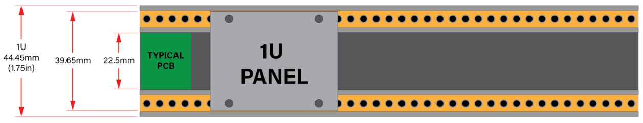
This module is designed for use within an Intellijel-standard 1U row, such as contained within the Intellijel 4U and 7U Eurorack cases. Intellijel’s 1U specification is derived from the Eurorack mechanical specification set by Doepfer that is designed to support the use of lipped rails within industry-standard rack heights.
Before Your Start
Intellijel Eurorack modules are designed to be used with a Eurorack-compatible case and power supply. We recommend you use Intellijel cases and power supplies. Before installing a new module in your case, you must ensure your power supply has a free power header and sufficient available capacity to power the module:
- Sum up the specified +12V current draw for all modules, including the new one. Do the same for the -12 V and +5V current draw. The current draw will be specified in the manufacturer’s technical specifications for each module.
- Compare each of the sums to specifications for your case’s power supply.
- Only proceed with the installation if none of the values exceeds the power supply’s specifications. Otherwise, you must remove modules to free up capacity or upgrade your power supply. You will also need to ensure your case has enough free space (hp) to fit the new module. To prevent screws or other debris from falling into the case and shorting any electrical contacts, do not leave gaps between adjacent modules, and cover all unused areas with blank panels. Similarly, do not use open frames or any other enclosure that exposes the backside of any module or the power distribution board. You can use a tool like a modular grid to assist in your planning. Failure to adequately power your modules may result in damage to your modules or power supply. If you are unsure, please contact us before proceeding.
Installing Your Module
When installing or removing a module from your case always turn off the power to the case and disconnect the power cable. Failure to do so may result in serious injury or equipment damage. Ensure the 10-pin connector on the power cable is connected correctly to the module before proceeding. The red stripe on the cable must line up with the -12V pins on the module’s power connector. Different modules use different ways to indicate the -12V pins. Some may be labeled with “-12V;” a white stripe next to the -12V pins; the words “red stripe;” or some combination of these. Additionally, some modules may have shrouded headers, thus preventing backward connections.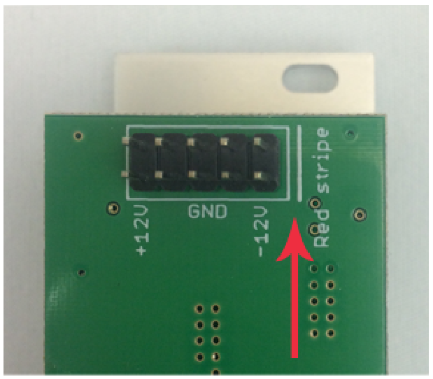 Most modules will come with the cable already connected but it is good to double-check the orientation. Be aware that some modules may have headers that serve other purposes so ensure the power cable is connected to the right one. The other end of the cable, with a 16-pin connector, connects to the power bus board of your Eurorack case. Ensure the red stripe on the cable lines up with the -12V pins on the bus board. On Intellijel power supplies the pins are labeled with the label “-12V” and a thick white stripe:
If you are using another manufacturer’s power supply, check their documentation for instructions.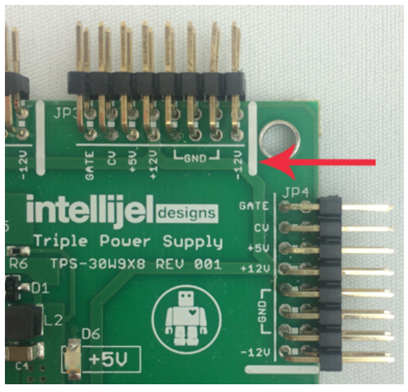 Once connected, the cabling between the module and power supply should resemble the picture below:
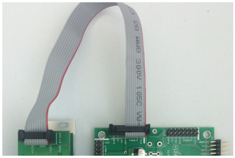
Before reconnecting power and turning on your modular system, double-check that the ribbon cable is fully seated on both ends and that all the pins are correctly aligned. If the pins are misaligned in any direction or the ribbon is backward you can cause damage to your module, power supply, or other modules. After you have confirmed all the connections, you can reconnect the power cable and turn on your modular system. You should immediately check that all your modules have powered on and are functioning correctly.If you notice any anomalies, turn your system off right away and check your cabling again for mistakes.
Front Panel Controls
 Controls
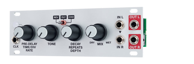
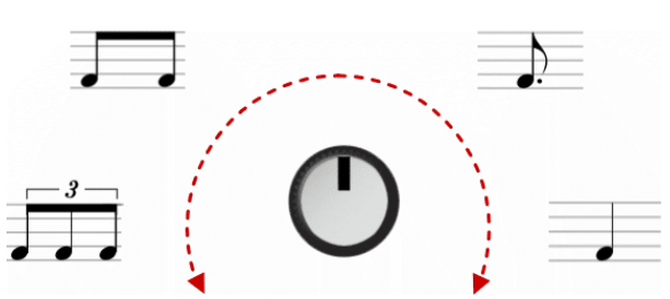 A. FX TYPE switch – 3-way switch determines whether Multi-FX functions as az Reverb ( REV ), Delay ( DLY ) or Chorus (CHO ).B. TIME knob – Adjusts the appropriate time-based parameter for either the REV (reverb), DLY (delay), or CHO (chorus) effect (as selected with the FX TYPE [A] switch), as labeled beneath the knob. Specifically:● REV (reverb) Mode – If the FX TYPE [A] switch is set to REV, this knob controls the reverb’s PRE-DELAY time. Turn the knob clockwise to increase the pre-delay. In REV mode, this knob is not clocked, meaning both the CLK [5] input and TAP TIME [C] buttons are ignored.● DLY (delay) Mode – If the FX TYPE [A] switch is set to DLY, this knob controls the delay time, and is labeled TIME/DIV. If the delay is clocked (using either the TAP TIME [C] button or the CLK [5] input), this knob sets the rhythmic division (DIV). Fully clockwise, the delay time equals the clock time, which is defined as a quarter note. As you turn the knob counterclockwise, the delay becomes dotted-8th notes (around 2:00); 8th notes (around 10:00); and 8th note triplets (when fully counterclockwise). Note that the TAP TIME [C] button always flashes on the quarter note, regardless of the TIME [B] knob position.
 If the delay is unclocked (i.e., the TAP TIME button not flashing), then the TIME [B] knob sets the delay from 50ms (fully counterclockwise) to 1000ms (fully clockwise) in several discrete intervals.● CHO (chorus) mode – If the FX TYPE [A] switch is set to CHO, this knob controls the chorus RATE (as indicated by the label). Turn the knob clockwise to increase the chorus rate, and turn it counterclockwise to decrease the rate. In CHO mode, this knob is not clocked, meaning both the CLK [5] input and TAP TIME [C] buttons are ignored. C. TAP TIME button – This button is used only in DLY (delay) mode. Its function is ignored by REV (reverb) and CHO (chorus) modes. The button has two different functions:● Sets Internal Clock Rate – Tap the button repeatedly (at least twice in a row) on the quarter-note to set an internal clock rate for the delay. If the delay is internally clocked, the button is half-lit but blinks brightly every quarter-note.● Disables Clock – Long-press the button (>1 sec) to turn off the internal clock, allowing you to use the delay in un-clocked mode (meaning the TIME [B] knob sets the delay time from 50 ms to 1000 ms in several discrete steps). If the delay is un-clocked, the button is half-lit but does not flash. When the CLK [5] input is used, the delay is externally (rather than internally) clocked. In this situation, the button is unlit but blinks at half-brightness every quarter note. The CLK LED [5] also blinks when the CLK input is used). Multi FX 1U will not operate in un-clocked mode if the CLK input is used.NOTE: When clocked (internally or externally) the TAP TIME [C] button always flashes on the clock (quarter-note) regardless of where the TIME [B] knob is set.
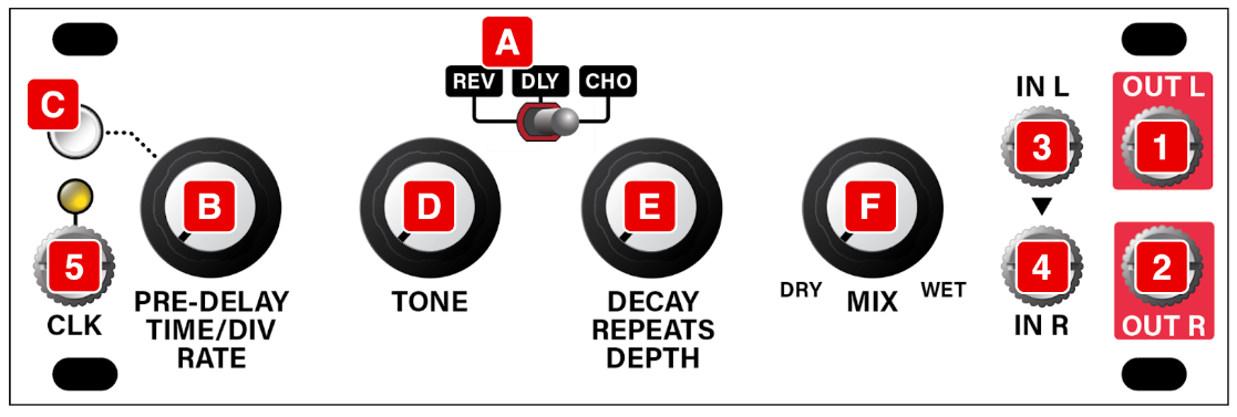 D. TONE Knob – This knob is active for all three modes, and it controls a simple low pass filter. Turning it counterclockwise “dulls” the tone by decreasing the high-frequency content. This can decrease the perceived ‘liveliness’ in the reverb, or allow for increasingly duller ‘taps’ as a delay fades out (as might happen with a tape delay). E. AMOUNT Knob – The function of this knob changes, depending on the model you’ve selected with the FX TYPE [A] switch). The function for each mode is labeled beneath the knob. Specifically:● REV (reverb) mode – The knob controls the reverb’s DECAY time. Clockwise = longer reverbs.● DLY (delay) mode – The knob sets the number of REPEATS. Clockwise = more repeats (higher feedback).● CHO (chorus) mode – The knob controls the DEPTH of the chorus effect. F. MIX Knob – Sets the amount of Dry vs Wet signal sent to the OUT L [1] and OUT R [2] jacks. When fully counterclockwise, only the dry, unaffected signal is sent to the outputs. When fully clockwise, only the wet, fully-effected signal is sent to the outputs. When set to the noon position, equal amounts of wet and dry signals appear at the outputs.
Inputs & Outputs
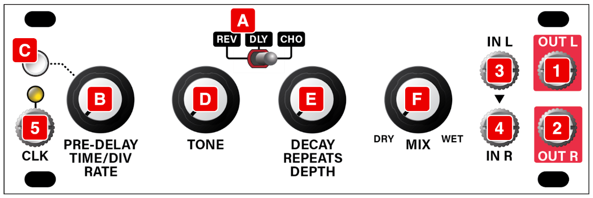
1. OUT L – Left output jack. Some effects are stereo and some are mono. See below.2. OUT R – Right output jack. Some effects are stereo and some are mono. Specifically:● REV (reverb) Mode – The reverb effect is stereo. Should you wish to output a mono reverb signal, simply connect to either the OUT L or OUT R output.● DLY (delay) Mode – The delay effect is mono, so the OUT L and OUT R output signals are identical.● CHO (chorus) Mode – The chorus effect is stereo. Should you wish to output a mono chorus signal, we recommend connecting both the OUT L and OUT R jacks to a mixer (such as an Intellijel Mixup module), and summing the channels to mono that way. Because of the phasing offsets applied to the left and right outputs, this method will result in a richer, more pleasing mono chorusing effect. However, you can also connect a single output, if that’s the sound you prefer.3. IN L – Left input (if running a stereo signal into Multi-FX) or mono input (if using Multi-FX as a mono effects module).4. IN R – Right input (if running a stereo signal into Multi-FX). This jack is normalled to the IN L [3] jack, so if nothing is plugged into the IN R jack, then a duplicate of the left input signal appears here. NOTE: The Left and Right inputs are summed to mono prior to being sent into the effects processor.5. CLK IN (and LED) – This jack is used only in DLY (delay) mode. It’s ignored by REV (reverb) and CHO (chorus) modes. A clock patched into this jack defines the value of a quarter-note in DLY (delay) mode. It overrides any internal clock rate set previously with the TAP TIME [C] button. Also, if MULTI FX 1U is currently set to un-clocked mode, patching into the CLK jack will automatically turn clock mode on. The actual delay time is based on this input as well as the clock division set by the TIME/DIV [B] knob. The CLK input has an associated LED, which blinks in time with the clock input, regardless of the IME/DIV knob position.
Technical Specifications
| Width | 24 hp |
| Maximum Depth | 33 mm |
| Current Draw | 130 mA @ +12V12 mA @ -12V |
References
[xyz-ips snippet=”download-snippet”]