intellijel N13-7968 Chainable Mono/Stereo Audio Utility Mixer
COMPLIANCE
This device complies with Part 15 of the FCC Rules. Operation i s subject to the following two conditions: (1) this device may not cause harmful interference, and (2) this device must accept any interference received, including interference that may cause undesired operation.Changes or modifications not expressly approved by Intellijel Designs, Inc. could void the user’s authority to operate the equipment.Any digital equipment has been tested and found to comply with the limits for a Class A digital device, pursuant to part 15 of the FCC Rules. These limits are designed to provide reasonable protection against harmful interference when the equipment is operated in a commercial environment. This equipment generates, uses, and can radiate radio frequency energy and, if not installed and used in accordance with the instruction manual, may cause harmful interference to radio communications.
This device meets the requirements of the following standards and directives:EMC: 2014/30/EUEN55032:2015 ; EN55103-2:2009 (EN55024) ; EN61000-3-2 ; EN61000-3-3Low Voltage: 2014/35/EUEN 60065:2002+A1:2006+A11:2008+A2:2010+A12:2011RoHS2: 2011/65/EUWEEE: 2012/19/EU
INSTALLATION
This module is designed for use within an Intellijel-standard 1U row, such as contained within the Intellijel 4U, 7U and Palette Eurorack cases. Intellijel’s 1U specification i s derived from the Eurorack mechanical specification set by Doepfer that is designed to support the use of lipped rails within industry standard rack heights.

Because this is a passive module, it requires no power to operate.

Before Your Start
Intellijel Eurorack modules are designed to be used with a Eurorack-compatible case and power supply. We recommend you use Intellijel cases and power supplies.Before installing a new module i n your case, you must ensure your power supply has a free power header and sufficient available capacity to power the module:
- Sum up the specified +12V current draw for all modules, including the new one. Do the same for the -12 V and +5V current draw. The current draw will be specified in the manufacturer’s technical specifications for each module.
- Compare each of the sums to specifications for your case’s power supply.
- Only proceed with installation if none of the values exceeds the power supply’s specifications.Otherwise you must remove modules to free up capacity or upgrade your power supply.
You will also need to ensure your case has enough free space (hp) to fit the new module. To prevent screws or other debris from falling into the case and shorting any electrical contacts, do not leave gaps between adjacent modules, and cover all unused areas with blank panels. Similarly, do not use open frames or any other enclosure that exposes the backside of any module or the power distribution board.
You can use a tool like ModularGrid to assist in your planning. Failure to adequately power your modules may result in damage to your modules or power supply. If you are unsure, please contact us before proceeding.
Installing Your Module
When installing or removing a module from your case always turn off the power to the case and disconnect the power cable. Failure to do so may result in serious injury or equipment damage. Ensure the 10-pin connector on the power cable is connected correctly to the module before proceeding.The red stripe on the cable must line up with the -12V pins on the module’s power connector. The pins are indicated with the label -12V, a white stripe next to the connector, the words “red stripe”, or some combination of those indicators. On Intellijel power supplies the pins are labelled with the label “-12V” and a thick white stripe.Sometimes the connectors are shrouded, ensuring the cable can only be oriented in one direction.Most modules will come with the cable already connected but it is good to double check the orientation. Be aware that some modules may have headers that serve other purposes so ensure the cable is connected to the right one.

The other end of the cable, with a 16-pin connector, connects to the power bus board of your Eurorack case. Ensure the red stripe on the cable lines up with the -12V pins on the bus board. On Intellijel power supplies the pins are labelled with the label “-12V” and a thick white stripe. Sometimes the connectors are shrouded, ensuring the cable can only be oriented in one direction.If you are using another manufacturer’s power supply, check their documentation for instructions.Once connected, the cabling between the module and power supply should resemble the picture below: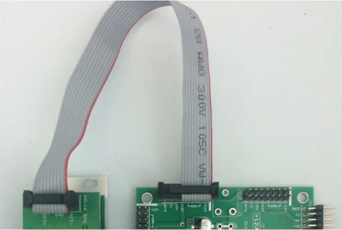
Before reconnecting power and turning on your modular system, double check that the ribbon cable is fully seated on both ends and that all the pins are correctly aligned. If the pins are misaligned in any direction or the ribbon is backwards you can cause damage to your module, power supply, or other modules.After you have confirmed all the connections, you can reconnect the power cable and turn on your modular system. You should immediately check that all your modules have powered on and are functioning correctly. If you notice any anomalies, turn your system off right away and check your cabling again for mistakes.
OVERVIEW
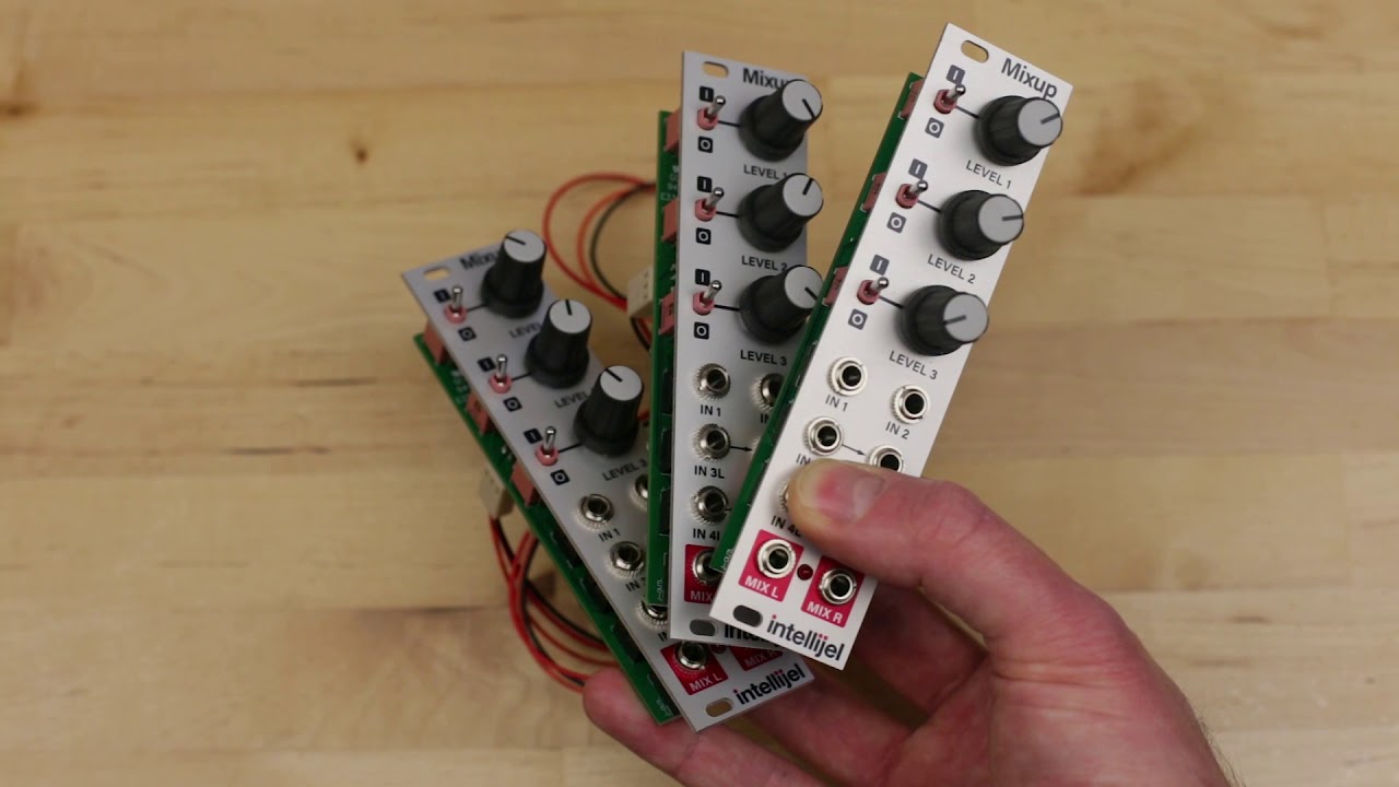
Stereo Mixer 1U i s a versatile, expandable audio mixer for the Intellijel 1U format. It has two pairs of front panel inputs, each with its own level control, and a mixed output pair. For each input pair, the left channel is normalled to the right channel, for mono operation.Using 3-pin Link connectors on the back panel, you can chain multiple Stereo Mixer 1U’s together in series, giving you the ability to mix together even more inputs, or to create sub-mixes for routing audio around larger systems. You can also these same connectors to patch Intellijel’s Mixup and XY IO 1U modules to these back-panel chains, and you can connect them directly to the ¼” audio jacks on an Intellijel Palette Case, a 7U case with 2nd-generation Audio Jacks Board, an Outs module, or a v2 Headphones 1U.Because Stereo Mixer 1U is designed specifically for audio (and not for CV mixing), it’s AC-coupled, and uses audio-grade, logarithmic attenuators for a smooth, even response across the entire volume range.
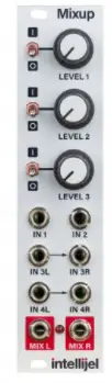
FRONT PANEL
- LEVEL 1 : T his knob reduces the level of the signal patched into I N 1L [ A] and I N 1R [ B], prior to sending it out the M IX L [ E] & M IX R [ F] jacks. Use it along with the L EVEL 2 [ 2] knob to establish the desired output mix.
- LEVEL 2 : T his knob reduces the level of the signal patched into I N 2L [ C] and I N 2R [ D], prior to sending it out the M IX L [ E] & M IX R [F] jacks. Use it along with the L EVEL 1 [ 1] knob to establish the desired output mix.
- OUTPUT LEVEL LED : T his LED lights when the sum of all the inputs (front panel j acks plus the back panel 3-pin Link connector) causes either side of the mixed stereo output to clip. Obviously, the more inputs you feed into the Stereo Mixer 1U (or the more Stereo Mixer 1U’s and/or Mixups you feed into each other), the greater the potential to overdrive the Mix bus. So i f the CLIP LED lights, consider reducing the various LEVEL knobs to maintain a clean, unclipped output.
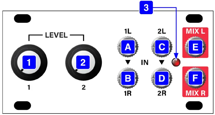
A: IN 1L : T his is the l eft side of stereo audio input 1. Audio is routed from I N 1L to the M IX L [ E] output, at the level determined by the L EVEL 1 [ 1] knob. If nothing is plugged into I N 1R [ B], then I N 1L is used as a mono input, and the signal is routed to both the M IX L [ E] and M IX R [ F] outputs.B: IN 1R : T his is the right side of stereo audio input 1. Audio is routed from I N 1R to the M IX R [ F] output, at the level determined by the LEVEL 1 [ 1] knob. If you l eave IN 1R unpatched, then any signal arriving at I N 1L [ A] is normalled to I N 1R.C: IN 2L : T his is the l eft side of stereo audio input 2. Audio is routed from I N 2L to the M IX L [ E] output, at the level determined by the L EVEL 2 [ 2] knob. If nothing is plugged into I N 2R [ D], then I N 2L is used as a mono input, and the signal is routed to both the M IX L [ E] and M IX R [ F] outputs.D: IN 2R : T his is the right side of stereo audio input 2. Audio is routed from I N 2R to the M IX R [ F] output, at the level determined by the L EVEL 2 [ 2] knob. If you l eave IN 2R unpatched, then any signal arriving at I N 2L [ C] is normalled to I N 2R.E: MIX L : T his is the mixed output of all the signals on the l eft bus (i.e., the attenuated levels of IN 1L [ A] and I N 2L [ C], plus any audio arriving via the 3-pin Link connector on the back panel).F: MIX R : T his is the mixed output of all the signals on the right bus (i.e., the attenuated levels of IN 1R [ B] and I N 2R [ D]) , plus any audio arriving via the 3-pin Link connector on the back panel).
BACK PANEL
Each Stereo Mixer 1U module features a pair of rear panel 3-pin Link connectors, which enable you to serially connect multiple Stereo Mixer 1U (and/or the Intellijel Mixup or XY IO 1U) modules to create a larger mixer with more inputs, or to connect the Stereo Mixer 1U directly to the ¼” j acks on a compatible Intellijel case, and other compatible Intellijel modules.
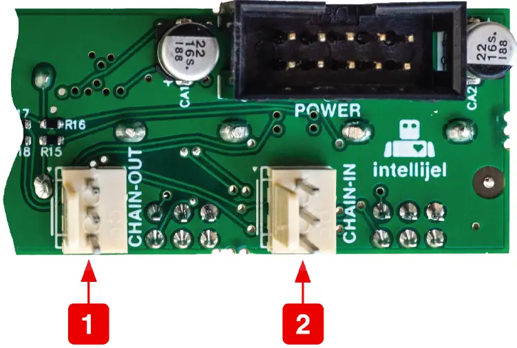
- CHAIN-OUT – This connector taps into the Left and Right O UT bus. Use the supplied l ink cable to connect the C HAIN-OUT of one Stereo Mixer 1U to the C HAIN-IN connector on another compatible module (such as another Stereo Mixer 1U; a Mixup; an Outs module; or a v2 Headphones 1U). Alternatively, use i t to connect the module directly to the ¼” audio j acks on a compatible Intellijel case (such as one of the Palette series cases, or the 7U case). When used in this way, the case’s ¼” j acks become unbalanced Stereo Mixer module outputs.
- CHAIN-IN – This connector adds another pair of inputs directly to the Left and Right bus. Use the supplied l ink cable to connect the C HAIN-IN of one Stereo Mixer 1U to the C HAIN-OUT connector on another compatible module (such as another Stereo Mixer 1U or a Mixup).Alternatively, you may use this to connect the module directly to the ¼” audio j acks on a compatible Intellijel case (such as the Palette series, or the 7u case). When used i n this way, the case’s ¼” j acks become unbalanced inputs to the Stereo Mixer module.
IMPORTANT: Never use the 3-wire Link cable to directly connect a Stereo Mixer 1U module to an Intellijel Pedal I/O module. Although both modules use this same cable/connector they serve different purposes and carry different signals.The following sections illustrate a few of the many possible device connections offered by the back panel’s pair of 3-pin Link connectors.
Connecting Stereo Mix 1U to the Audio Jacks on your 7U CaseIf you have a 2nd generation Audio Jacks board installed in your Intellijel 7U Performance Case, you can connect one or two Stereo Mixer 1U’s directly to these jacks. This connection method does not work with a 1st generation Audio Jacks board, though you can purchase and easily install a 2nd generation board in your case.You can distinguish 1st generation boards (included with cases built before early 2019) by the single connector along the bottom of the Audio Jacks board. 2nd generation boards have a large shrouded header flanked by two smaller shrouded headers, flanked by two l ink connectors.

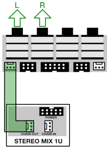
Output Connection
- Connect one end of the supplied 3-wire l ink cable to the CHAIN-OUT on your Stereo Mixer 1U.
- Connect the other end to either of the two 3-pin connectors on the Audio Jacks board. The l eft connector uses the two left j acks for L/R Stereo outputs, while the right connectoruses the two right jacks.In this scenario, the audio j acks work as unbalanced outputs.
Combining ModulesYou can connect up to two Stereo Mixer 1U modules to the Audio Jacks Board, or you can even combine a Stereo Mixer with another 2-channel module (such as a Mixup or a Pedal I/O 1U) .

Similarly, you can connect a Stereo Mixer’s C HAIN-IN connector to either of the two 3-pin Link connectors on the Audio Jacks board and feed external audio from the corresponding j acks into the Stereo Mixer 1U bus. The following illustration shows one Stereo Mixer being used as an output mixer, and the other as an input mixer.

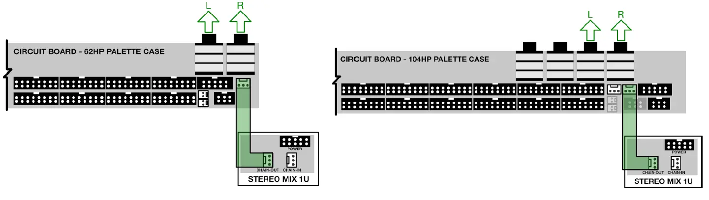
Connecting Stereo Mix 1U to the Audio Jacks on your Palette CaseIf you have an Intellijel Palette case, you can connect the Stereo Mixer 1U directly to a pair of ¼” audio j acks on the top of the Palette (there is one pair of ¼” audio j acks on the Palette 62, and two pairs on the Palette 104). You can choose whether you want the ¼” j acks to send audio out of the Stereo Mixer 1U, or into it.
To send unbalanced, line-level mixed audio directly out o f the Stereo Mixer 1U to a pair of ¼” audio j acks on the Palette, connect the 3-wire Link cable (provided with your Stereo Mixer module) between the Stereo Mixer’s C HAIN-OUT connector and a 3-pin Link connector on your Palette. There is only a single pair of ¼” j acks on the Palette 62, so there i s only one 3-pin Link connector. The Palette 104 has two pairs of ¼” j acks, so there are two 3-pin Link connectors you can connect the Stereo Mixer 1U to either of the Palette 104’s two 3-pin Link connectors, depending on which pair of ¼” j acks you wish to use.
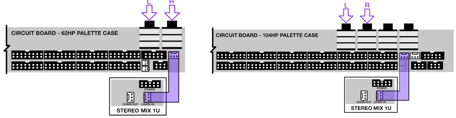
To send unbalanced, live-level audio directly into the Stereo Mixer 1U from a pair of ¼” audio jacks on the Palette, connect the 3-wire l ink cable (provided with your Stereo Mixer module) between the Stereo Mixer’s C HAIN-IN connector and a 3-pin Link connector on your Palette.There is only a single pair of ¼” j acks on the Palette 62, so there is only one 3-pin Link connector. The Palette 104 has two pairs of ¼” j acks, so there are two 3-pin Link connectorsyou can connect the Stereo Mixer 1U to either of the Palette 104’s two 3-pin Link connectors, depending on which pair of ¼” jacks you wish to use.
Connecting Stereo Mix 1U to an Intellijel Outs ModuleIf you own an Intellijel Outs module, you can connect it directly to the Stereo Mixer 1U using the included l ink cable. To do so:
- Using the 3-wire link cable provided with your Stereo Mixer 1U module, connect one end of it to the C HAIN-OUT 3-pin connector on the Stereo Mix, and the other end to the 3-pin connector on the Outs module.
- IMPORTANT! O n the back of the Outs module, remove the JP1 jumper connector and put it in a safe place.This jumper is what normals the Outs module’s Left input to its Right input. Since the Stereo Mixer 1U module has its own Left-to-Right normaling, 3-pin Link connections requireremoval of this jumper to achieve expected operation and optimum sonic fidelity.

Stereo Mixer 1U’s M IX L and M IX R signals are now sent directly to the l eft and right inputs on your Outs module without patching the front panels.
Connecting Stereo Mix 1U to a v2 Headphones 1U ModuleIf you own an Intellijel Headphones 1U module (version 2 only), you can connect it directly to the Stereo Mixer 1Uusing the included l ink cable. To do so:
- Confirm you have a “version 2” Headphones 1U module.Version 2 modules, in production since August 2019, have a 3-pin Link connector and a jumper on the rear panel. Version 1 modules do not.

- Using the included 3-wire l ink cable, connect one end of it to the C HAIN-OUT 3-pin connector on the Stereo Mixer 1U, and the other end to the 3-pin input connector on the Headphones 1U module.
- IMPORTANT! O n the back of the Headphones 1U module, remove the JP1 jumper connector and put it in a safe place.This jumper is what normals the Headphones 1U module’s Left input to its Right input. Since the Stereo Mixer module has is own Left-to-Right normaling, 3-pin Link connectionsrequire removal of this jumper to achieve expected operation and optimum sonic fidelity.
- Stereo Mixer’s M IX L and M IX R signals are now duplicated directly to the left and right inputs on your Headphones 1U module without patching the front panels.

TECHNICAL SPECIFICATIONS
| Width | 16 hp |
| Maximum Depth | 25 mm |
| Current Draw | 17mA @ +12V
6mA @ -12V |
 report this ad
![]()
References
[xyz-ips snippet=”download-snippet”]