Palette Cases
4U Powered, Shallow Eurorack Cases
Palette 104104HP; MIDI IN/OUT; 3 Buff Mults, 2 Summers; 4 ¼” Audio Jacks
Palette 6262 HP; MIDI IN; 2 Buff Mults; 2 ¼” Audio Jacks
Manual Revision: 2020.11.30
COMPLIANCE
This device complies with Part 15 of the FCC Rules. Operation is subject to thefollowing two conditions: (1) this device may not cause harmful interference, and (2) this device must accept any interference received, including interference that may cause undesired operation. Changes or modifications not expressly approved by Intellijel Designs, Inc. could void the user’s authority to operate the equipment. Any digital equipment has been tested and found to comply with the limits for a Class A digital device, pursuant to part 15 of the FCC Rules. These limits are designed to provide reasonable protection against harmful interference when the equipment is operated in a commercial environment. This equipment generates, uses, and can radiate radio frequency energy and, if not installed and used in accordance with the instruction manual, may cause harmful interference to radio communications.
 This device meets the requirements of the following standards and directives: EMC: 2014/30/EU EN55032:2015 ; EN55103-2:2009 (EN55024) ; EN61000-3-2 ; EN61000-3-3Low Voltage: 2014/35/EU 60065:2002+A1:2006+A11:2008+A2:2010+A12:2011RoHS2: 2011/65/EU WEEE: 2012/19/EUPalette Cases Manual
OVERVIEW
Intellijel’s Palette cases are compact enough to slip into a small bag and shallow enough to rest comfortably on a desktop — yet their capabilities far exceed their size. They’re available in two widths: 62HP and 104HP, and each is as stylish as it is practical; as durable as it is portable, and every bit as flexible as your imagination allows.
62HP Version
- 62HP of both 3U space (for standard eurorack modules), and 1U space (for all those necessary little utility modules).
- Two built-in 1×4 buffered mults (chainable into a 1 x 8) with input level/polarity LEDs.
- Built-in MIDI Input (both USB and ⅛” TRS Type-A MIDI via the supplied 5-pin DIN adapter).
- Two ¼” TRS jacks, each of which can function as either an input or an output.
- Robust power circuit with 12 shrouded power connectors, and a 40W power brick capable of supplying up to 1.2A of both +12V and -12V to your Eurorack modules.
- Two 5V connectors, delivering up to 500mA between them.
- Access connectors for internally connecting I/O modules to the built-in MIDI and Audio Jacks
- Link connector for connecting equipped modules (like Mixup and Pedal IO) directly into the ¼” jacks.
TOP PANEL
The following describe all Palette Case features, though some are not present on the 62HP version:
- Power Input Socket
 Connect the included 15V center-pin-positive power adapter to this socket to provide power to your case. The Palette 62 uses a 40W adapter, while the Palette 104 uses a 60W adapter). To ensure proper power is applied to all your modules, use only Intellijel certified power adapters.
 - Power SwitchSwitch to “I” to power up the Palette, and all its connected modules. Switch to “0” to turn it off.
- MULT AThe first of two (62HP) or three (104HP) built-in 1 x 4 buffered signal multipliers. Plug an audio or CV signal into the left-most jack and a buffered duplicate of that signal appears at the four jacks to its right.To the left of the MULT’s input jack is an LED, whose brightness indicates the amount of voltage appearing at the input, and whose color indicates the polarity (with green signifying positive voltages, and red signifying negative).For more information about Buff Mults, see Understanding Buff Mults.
- MULT BThe second built-in 1 x 4 buffered signal multiplier. Plug an audio or CV signal into MULT B’s left-most jack, and a buffered duplicate of that signal appears at the four jacks to its right.MULT A is normally to MULT B. So if nothing is plugged into MULT B’s input, then MULT A’s input is duplicated across all 8 of MULT A & B’s outputs, making the two MULTS act as a single 1 x 8 buffered signal multiplier.
- MULT C (104HP OnlyAvailable only on the 104HP case, this is a third built-in 1 x 4 buffered signal multiplier. Plug an audio or CV signal into MULT C’s left-most jack, and a buffered duplicate of that signal appears at the four jacks to its right.MULT B is normally to MULT C. So if nothing is plugged into MULT C’s input, then MULT B’s input is duplicated across all 8 of MULT B & C’s outputs. Also, if nothing is plugged into MULT B’s input, then the signal appearing at MULT A’s input is duplicated across all 12 MULT outs.
- SUM A (104HP Only)Available only on the 104HP case, this is a summing module that adds two voltages together. Plug an audio or CV signal into SUM A’s left-most jack, and a second audio or CV signal into SUM A’s other input jack, and a sum of the two signals appears at its output.MULT C is normally to the left-most input of SUM A. So if nothing is plugged into SUM A’s left-most input, then the signal appearing at MULT C’s input is automatically sent into SUM A.
- SUM B (104HP Only)Available only on the 104HP case, this is a second summing module that adds two voltages together. Plug an audio or CV signal into SUM B’s left-most jack, and a second audio or CV signal into SUM B’s other input jack, and a sum of the two signals appears at its output.SUM A is normally to the left-most input of SUM B. So if nothing is plugged into SUM B’s left-most input, then the signal appearing at the output of SUM A is automatically sent into SUM B.
- TRS Audio JacksEach of these ¼” Neutrik TRS jacks can operate as either an audio input or an audio output depending on which modules you connect to the circuit board inside the Palette case. This allows you maximum flexibility when configuring your case — whether you wish to use these audio jacks as outputs for a Palette-based synthesizer; as inputs for a Palette-based effects device; or as a send/return for plugging external pedals or effects devices into your Palette’s signal chain.These jacks may be used with many different modules (not included), such as the following:● Stereo Line Out 1U: This module, when connected to an Audio Jacks Connector on the circuit board, sends balanced +4dBu audio out a pair of ¼” TRS jacks. Use this module to send audio from your Palette case to a mixer, amp, or DAW.● Stereo Line-In 1U: This module, when connected to an Audio Jacks Connector on the circuit board, receives balanced +4dBu audio from a pair of ¼” TRS jacks. Use this module to receive external audio for processing with other modules in your Palette case.● Pedal I/O 1U: This module, when connected to the Link Connector on the circuit board, addresses a pair of ¼” TRS jacks — sending an unbalanced line-level output to the left jack, and returning an unbalanced live-level input from the pair’s right jack. Use this module to patch external effects or stompboxes into your Palette.● Mixup 3U: This module, when connected to the Link Connector on the circuit board, sends the unbalanced L/R stereo mix from the rear-panel output of Mixup directly to a pair of ¼” jacks on Palette. Alternatively, you can connect Mixup so that it receives unbalanced audio from a pair of Palette’s ¼” jacks, instead.● Stereo Mix 1U: This module, when connected to the Link Connector on the circuit board, sends the unbalanced L/R stereo mix from the rear-panel output of the Stereo Mix 1U directly to a pair of ¼” jacks on Palette. Alternatively, you can connect Stereo Mix 1U so that it receives unbalanced audio from a pair of Palette’s ¼” jacks, instead.IMPORTANT: You should not attempt to connect multiple modules to a single pair of ¼” TRS jacks,as unexpected results may occur.NOTE: Palette Cases do not support Intellijel’s old Audio IO 1U module, and will not connect to it in any way.
- ⅛” TRS MIDI InputMIDI input connector on a ⅛” TRS (Type-A) jack. If you need to connect a 5-pin MIDI device, use the included Type-A ⅛” TRS-to-5-pin MIDI adapter. MIDI arriving at this jack is routed to the 10-pin MIDI Connector socket on the Palette’s circuit board, where it can be connected to a MIDI converter module, such as the Intellijel MIDI 1U.
- ⅛” TRS MIDI Output (104HP Only)MIDI output connector on a ⅛” TRS (Type-A) jack. When used with a MIDI 1U module, the jack functions as a MIDI Thru — passing along any MIDI data received at the ⅛” TRS MIDI Input [9] jack. If you need to connect a 5-pin MIDI device to this jack, you’ll need to purchase a standard Type-A ⅛” TRS-to-5-pin MIDI adapter. Or connect it directly (no adapter required) to any other device with a Type-A compatible TRS MIDI input (such as another Palette case, or any other device that supports the MIDI 2.0 standard Type-A TRS connection).
- USB MIDI InputMIDI input connector on USB. MIDI sent into the USB port is routed to the 10-pin MIDI Connectorthe socket on the Palette’s circuit board, where it can be connected to a MIDI input module, such as the Intellijel MIDI 1U or the older µMIDI 1U.
- Mounting for 1U modulesDepending on which Palette Case you own, this area provides either 62HP or 104HP of mounting space for Intellijel-format 1U modules.
- Mounting for 3U modulesDepending on which Palette Case you own, this area provides either 62HP or 104HP of mounting space for eurorack standard 3U modules, up to a depth of 45.5mm. At each of the extreme edges (occupying less than 1 hp), the depth is 37.42mm.
CIRCUIT BOARD
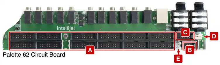
Running along the back edge of the Palette cases are their built-in circuit boards, which contain all of Palette’s audio, midi, power, and module connection circuitry.The jacks and switches that run along the top of the circuit board were discussed earlier in the Top Panel description. Below these jacks and switches, and facing into the case, are the various headers needed to connect your gear. These are:
[A] Power Connectors
These are the the16-pin power connectors for powering your modules. The Palette 62 has 12 connectors, and the Palette 104 has 24. The connectors are shrouded to ensure that properly manufactured ribbon cables can be connected only one way — with the red (-12V) wire to the right.Make sure, if you’re using cables from another manufacturer or sourced elsewhere, that the red stripe is on the right when plugged in. Plug the other end of the ribbon cables into the Eurorack modules you wish to power — being careful (if the module’s power connector isn’t shrouded) to align the red stripe with the -12V pins on the module. These pins are indicated differently by different manufacturers, but often will say “-12V,” or “Red Stripe,” or have a visible white stripe next to the -12V side of the connector. See your Eurorack modules for details concerning its -12V power nomenclature.
[B] Audio Jacks Connector
These 6-pin connectors are for attaching either a balanced audio input or balanced audio output module to the ¼” TRS connectors on the top of the Palette. The Palette 62 has one Audio Jacks Connector (for its single pair of TRS jacks), while the Palette 104 has two Audio Jacks Connectors (for its two pairs of TRS jacks). Some examples:
- Stereo Line Out 1U: Using the cable provided with your Stereo Line Out 1U module, connect it to the Audio Jacks Connector (or to one of the two Audio Jacks Connectors on the 104HP case). Once connected, the corresponding pair of Palette’s TRS audio jacks function as L/R audio outputs for the Palette case.
- Stereo Line-In 1U: Using the cable provided with your Stereo Line In 1U module, connect it to the Audio Jacks Connector (or to one of the two Audio Jacks Connectors on the 104HP case). Once connected, the corresponding pair of Palette’s TRS audio jacks function as L/R audio inputs for the Palette case.IMPORTANT: If you connect a module to the Audio Jacks Connector, you should not connect a module to the same audio pair’s Link Connector (described later), or unexpected results may occur.
[C] MIDI Connector
Connect this 10-pin connector to your Intellijel MIDI 1U or µMIDI 1U modules using the cable included with your MIDI module. This allows you to use the Pallete’s USB MIDI or ⅛” TRS MIDI Jack(s) for connecting your eurorack system to standard MIDI gear.
Stereo Line-In 1U: Using the cable provided with your Stereo Line In 1U module, connect it to the Audio Jacks Connector (or to one of the two Audio Jacks Connectors on the 104HP case). Once connected, the corresponding pair of Palette’s TRS audio jacks function as L/R audio inputs for the Palette case.
IMPORTANT: If you connect a module to the Audio Jacks Connector, you should not connect a module to the same audio pair’s Link Connector (described later), or unexpected results may occur.
[C] MIDI Connector
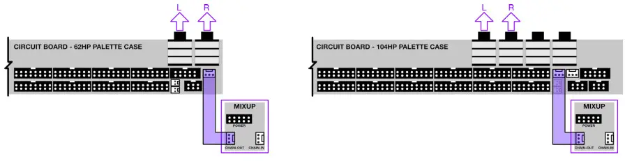
Connect this 10-pin connector to your Intellijel MIDI 1U or µMIDI 1U modules using the cable included with your MIDI module. This allows you to use the Pallete’s USB MIDI or ⅛” TRS MIDI Jack(s) for connecting your eurorack system to standard MIDI gear.[D] Link ConnectorUse this 3-pin connector to attach either a Mixup module or a Pedal I/O module to the two ¼”connectors on the top of the Palette.
● Mixup (OUT): Connect the 3-wire link cable (provided with your Mixup module), between the Link Connector on the Palette circuit board and the CHAIN-OUT connector on your Mixup.In this scenario, unbalanced stereo audio from Mixup’s output is sent out to Palette’s two corresponding Audio Jacks.● Mixup (IN): Connect the 3-wire link cable (provided with your Mixup module), between the Link Connector on the Palette circuit board and the CHAIN-IN connector on your Mixup.In this scenario, unbalanced stereo audio arriving at the Palette’s corresponding pair of Audio Jacks will be mixed with Mixup’s own front panel inputs.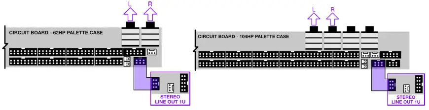 ● Pedal I/O 1U: Connect the 3-wire link cable between the Link Connector on the Palette and the one on your Pedal I/O.In this scenario, unbalanced audio is sent out Audio Jack 1 (or 3) to your external signal processor, and unbalanced audiocomes back from your external signal processor into Audio Jack 2 (or 4).
IMPORTANT: If you connect a module to the Links Connector, you should not connect a module to the same audio pair’s Audio Jacks Connector (described previously), or unexpected results may occur.
[E] 5V Connectors
Connect these 5V connectors to any modules that require a 5V power source. You can also use this to power an Intellijel USB Power 1U module, which (for example) is useful for connecting a small USB gooseneck LED light.
Connecting Two Audio Modules to the Palette 104 \Because the Palette 104 has two pairs of Audio Jacks, it’s possible to connect different devices to each pair of jacks. For example, you could connect two Stereo Line Out 1U modules (one to each 6-pin Audio Connector) to have 4 audio outputs. Or you could connect a Stereo Line Out 1U module to one 6-pin Audio Connector and a Stereo Line In 1U module to the other 6-pin Audio Connector to have one pair of audio inputs and one pair of audio outputs.
You can mix and match modules, as well. This example combines a Stereo Line Out 1U module and a Pedal IO 1U module giving you a pair of stereo outputs, plus effects send/return loop.
INSTALLATION TIPS
Palette was designed to provide maximum performance and compatibility in the smallest possible space. Because of this, and in accordance with those pesky little laws of physics, it can sometimes be a little tedious to plug and unplug the various cables into the circuit board at the rear of the case.Fortunately, there are a couple of things you can do to make the process quicker and easier:
- With the case completely empty, connect all of your power, link, 5V, 5-pin audio, and 10-pin MIDI cables to the Palette circuit board first. If you think you might swap out modules in the future (and, since this is Eurorack, you probably will), then it’s a good idea to connect a few more power cables to the circuit board than you currently need — that will make it easier to addadditional modules in the future.
- The circuit board is much more accessible if you first remove the top rail. With the rail removed, it’s much easier to plug the various connectors into the circuit board. To do this:
- Remove the two screws (one on each side of the case) that hold the top rail in place. Make note of the rail’s orientation, and set it aside.
- Connect all the necessary cables to the circuit board.
- Slide the rail back into place, and re-insert the screws on either side.
- Connect the cables to all your modules and screw them into the rails.
UNDERSTANDING BUFF MULTI
“Buff Mult” is vernacular shorthand for “Buffered Multiplier.” A buff mult takes a single input signal and routes it to multiple outputs simultaneously. For example, you might want to route a keyboard’s pitch CV to three different destinations: one to govern the pitch of your main oscillator; another to govern the pitch of a second oscillator, and the third to open and close a filter so that it tracks across the keyboard.
Unlike a passive mult, which merely splits the incoming signal and shares it across multiple outputs (much like a Y-cable), buffered mults make electrical copies of an input voltage and duplicate that voltage at the outputs.
Buffered mults have a few advantages over passive multi. Because buffered multi isolate their outputs from the input, any faults or shorts present at the input will not pass through to a connected module. Also, in a passive mult, what you connect to output can cause a slight variation in the voltages that it sends. In some situations (like an LFO or envelope), this probably won’t have any sonic effect on your patch. But for voltage-critical functions (like an oscillator, where only a slight change in voltage is easily heard), it’s often better to use a buffered mult, since this ensures that the 1V/Oct signal arrives at its input will be electrically and accurately duplicated across all its outputs.
Your Palette 62 has two Buff Mults, and your Palette 104 has three. Each is a stand-alone 1 IN x 4 OUT buffered multiplier. Plug an audio or CV signal into MULT A’s input jack, and a buffered duplicate of that signal is sent out the four jacks to its right. Similarly, an audio or CV signal patched into MULT B’s input jack is duplicated at the other four jacks in the group.
The input of each MULT is normalled to the previous. So if nothing is plugged into MULT B’s input jack, then the input to MULT A is multiplied and sent to eight outputs (four from MULT A and four from MULT B), giving you a single 1 x 8 buffered signal multiplier. Similarly, on Palette 104, if nothing is plugged into either MULT B or MULT C’s input jacks, then the input to MULT A is multiplied and sent to all twelve outputs.
TECHNICAL SPECIFICATIONS
Palette 62
| Dimensions | 324.4 x 204.4 x 51.3 (mm)|(58.5 mm high, when including rubber feet/jacks) 12.77″ x 8.05″ x 2.02″|(2.3″ high, when including rubber feet/jacks) 62 hp for 3U modules + 62 hp for 1U modules |
| Maximum Module Depth | 45.5 mm for middle 60HP 37.42mm at each 1HP edge |
| Current Supplied | 1.2A @ 12V1.2A @ -12V500mA @ +5V 40W Power Brick |
Palette 104
| Dimensions | 537.7 x 204.4 x 51.3 (mm)
(58.5 mm high, when including rubber feet/jacks) 21.17″ x 8.05″ x 2.02″ (2.3″ high, when including rubber feet/jacks) 104 hp for 3U modules + 104 hp for 1U modules |
| Maximum Module Depth | 45.5 mm for middle 102HP 37.42 mm at each 1 HP edge |
| Current Supplied | 1.5 12V
 report this ad report this ad500 mA @ +5V 60W Power Brick |
[xyz-ips snippet=”download-snippet”]