intellijel Quad VCA Voltage Controlled Amplifier and Cascaded Mixer
COMPLIANCE
This device complies with Part 15 of the FCC Rules. Operation is subject to the following two conditions: (1) this device may not cause harmful interference, and (2) this device must accept any interference received, including interference that may cause undesired operation. Changes or modifications not expressly approved by Intellijel Designs, Inc. could void the user’s authority to operate the equipment. Any digital equipment has been tested and found to comply with the limits for a Class A digital device, pursuant to part 15 of the FCC Rules. These limits are designed to provide reasonable protection against harmful interference when the equipment is operated in a commercial environment. This equipment generates, uses, and can radiate radio frequency energy and, if not installed and used in accordance with the instruction manual, may cause harmful interference to radio communications.
This device meets the requirements of the following standards and directives:EMC: 2014/30/EUEN55032:2015 ; EN55103-2:2009 (EN55024) ; EN61000-3-2 ; EN61000-3-3
Low Voltage: 2014/35/EUEN 60065:2002+A1:2006+A11:2008+A2:2010+A12:2011
RoHS2: 2011/65/EUWEEE: 2012/19/EU
INSTALLATION
Intellijel Euro rack modules are designed to be used with a Eurorack-compatible case and power supply. We recommend you use Intellijel cases and power supplies.Before installing a new module in your case, you must ensure your power supply has a free power header and sufficient available capacity to power the module:
- Sum up the specified +12V current draw for all modules, including the new one. Do the same for the -12 V and +5V current draw. The current draw will be specified in the manufacturer’s technical specifications for each module.
- Compare each of the sums to specifications for your case’s power supply.
- Only proceed with installation if none of the values exceeds the power supply’s specifications. Otherwise you must remove modules to free up capacity or upgrade your power supply.
You will also need to ensure your case has enough free space (hp) to fit the new module. To prevent screws or other debris from falling into the case and shorting any electrical contacts, do not leave gaps between adjacent modules, and cover all unused areas with blank panels. Similarly, do not use open frames or any other enclosure that exposes the backside of any module or the power distribution board.You can use a tool like ModularGrid to assist in your planning. Failure to adequately power your modules may result in damage to your modules or power supply. If you are unsure, please contact us before proceeding.
Installing Your Module
When installing or removing a module from your case always turn off the power to the case and disconnect the power cable. Failure to do so may result in serious injury or equipment damage.Ensure the 10-pin connector on the power cable is connected correctly to the module before proceeding. The red stripe on the cable must line up with the -12V pins on the module’s power connector. The pins are indicated with the label -12V, a white stripe next to the connector, the words “red stripe”, or some combination of those indicators.Most modules will come with the cable already connected but it is good to double check the orientation. Be aware that some modules may have headers that serve other purposes so ensure the cable is connected to the right one.
The other end of the cable, with a 16-pin connector, connects to the power bus board of your Eurorack case. Ensure the red stripe on the cable lines up with the -12V pins on the bus board. On Intellijel power supplies the pins are labelled with the label “-12V” and a thick white stripe:
If you are using another manufacturer’s power supply, check their documentation for instructions.
Once connected, the cabling between the module and power supply should resemble the picture below: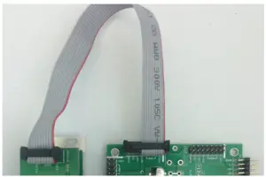 Before reconnecting power and turning on your modular system, double check that the ribbon cable is fully seated on both ends and that all the pins are correctly aligned. If the pins are misaligned in any direction or the ribbon is backwards you can cause damage to your module, power supply, or other modules.After you have confirmed all the connections, you can reconnect the power cable and turn on your modular system. You should immediately check that all your modules have powered on and are functioning correctly. If you notice any anomalies, turn your system off right away and check your cabling again for mistakes.
OVERVIEW
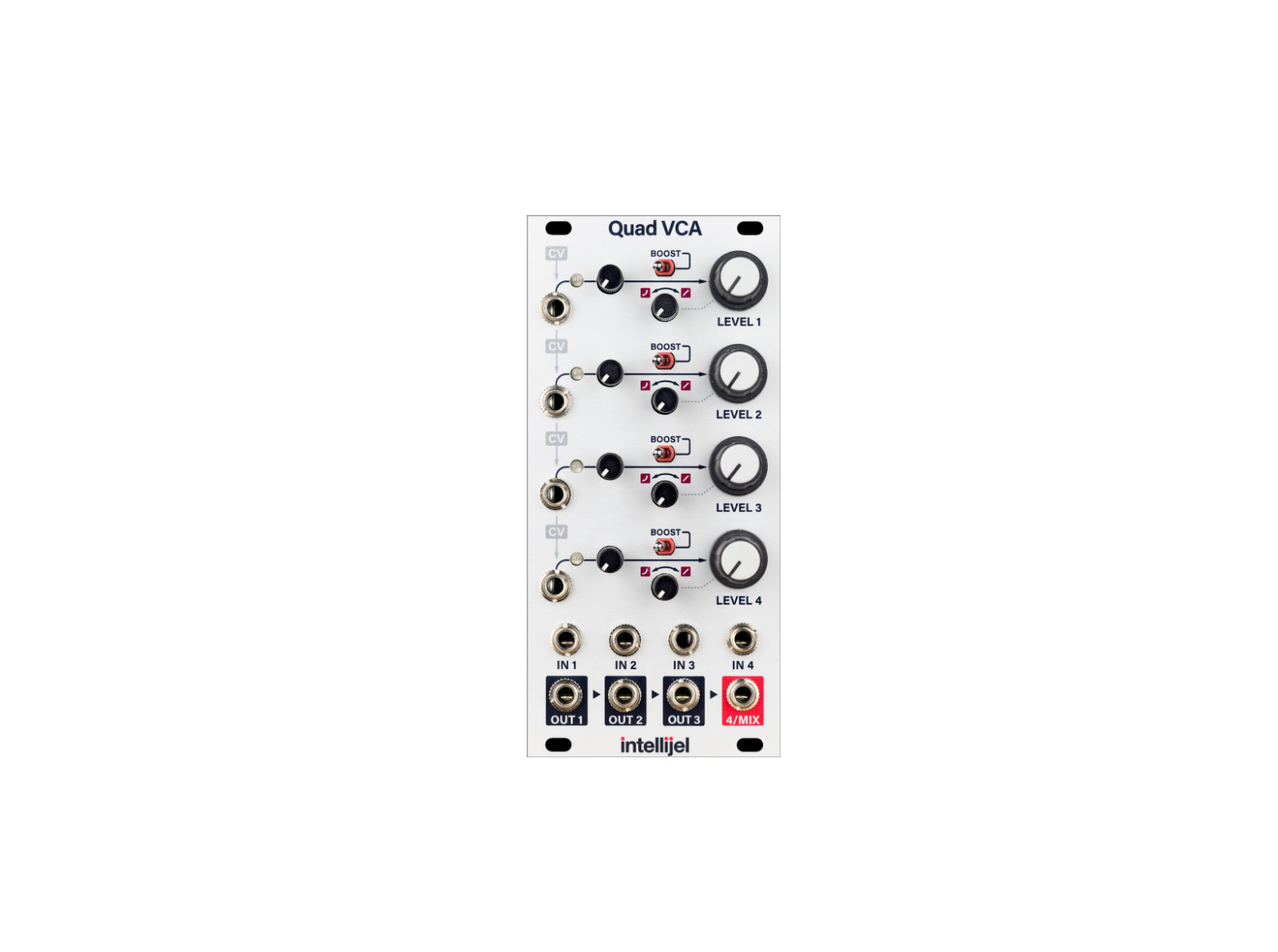
The Intellijel Quad VCA is a versatile four channel variable response VCA. It features cascaded CV inputs and cascaded mix outputs allowing it to be used in a number of versatile configurations. A boost switch provides additional amplification for low level signals or a subtle overdrive for audio. More than just simply four VCAs, the Quad VCA is bound to be useful in any patch.
Features
- Manual LEVEL control per VCA which is convenient when using the module as a mixer or for biasing when CV modulating the VCA with a bipolar LFO.
- Dedicated CV attenuators with dual color LEDs for monitoring bipolar CV signals.
- Continuously adjustable response from linear to exponential per VCA.
- Each CV input is normalled to the adjacent one for cascaded control.
- Each output is normalled to the mix input of the adjacent one which allows you to use adjacent sets as submixes or the fourth output can be used as a master mix output when none of the other outputs are patched.
- Each VCA has a BOOST switch that increases the output level by approximately +6dB (double).
FRONT PANEL
Controls
[1] CV Attenuator – Controls the amount of CV modulation sent to control a channel’s level. Because the CV inputs cascade, if there is no CV input on a channel, but a preceding channel has a CV input, this knob will bring up that previous channel’s CV signal.
[2] CV LED – Each of the four channels has a red/green LED whose intensity shows the post-attenuator level of the incoming CV signal. It lights green for positive voltages and red for negative.
[3] Linear / Exponential Response This attenuator controls the response of the channel’s VCA to the LEVEL knob and CV input. When fully counterclockwise the response of the channel’s VCA is exponential. When turned fully clockwise the response is linear. In-between settings provide a variable response between the two extremes.
[4] BOOST – When this switch is set to the left position (disabled) the maximum linear gain of the channel’s VCA when the LEVEL knob is fully clockwise or +5 V is applied to the CV input is approximately unity (1:1). When set to the right position (enabled) the signal is boosted by around +6 dB (2:1).
[5] LEVEL 1 – Sets the base level, or bias, of the channel’s VCA. When fully clockwise this approximately equivalent to applying a +5 V voltage at the CV input. In the fully linear response this results in unity (1:1) gain. The knob level is summed with the channel’s CV input.
[6] LEVEL 2 – Sets the base level of channel 2.
[7] LEVEL 3 – Sets the base level of channel 3.
[8] LEVEL 4 – Sets the base level of channel 4.
Inputs and Outputs
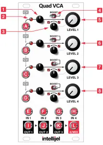
[A] CV 1 – The CV input for controlling the level of channel 1. A +5 V input with the channel’s attenuator fully clockwise, response knob fully linear, and LEVEL control fully counterclockwise results in approximately unity (1:1) gain.
[B] CV 2 – The CV input for controlling the level of channel 2. If nothing is connected to this jack, the CV is taken from CV 1.
[C] CV 3 – The CV input for controlling the level of channel 3. If nothing is connected to this jack, the CV is taken from CV 2.
[D] CV 4 – The CV input for controlling the level of channel 4. If nothing is connected to this jack, the CV is taken from CV 3.
[E] IN 1 – The input to channel 1.
[F] IN 2 – The input to channel 2.
[G] IN 3 – The input to channel 3.
[H] IN 4 – The input to channel 4.
[I] OUT 1 – The signal output for channel 1. If nothing is connected to this jack the output is mixed into OUT 2.
[J] OUT 2 – The signal output for channel 2. If nothing is connected to this jack the output is mixed into OUT 3.
[K] OUT 3 – The signal output for channel 3. If nothing is connected to this jack the output is mixed into OUT 4.
[L] OUT 4/MIX – The signal output for channel 4. If the other three OUT jacks are left unconnected, this jack can function as the output of a 4-channel mix.
INSTRUCTIONS
4 Independent VCAs
The simplest way to use the Quad VCA is to ignore any of the cascading CV and mixing functionality and just use it as four independent VCAs:
- Connect the output signal from the source to IN 1. The source can be anything, any oscillator, LFO, envelope, or any other audio or CV generator.
- Connect OUT 1 to the input of the destination.
- Connect a modulating signal to CV 1. The modulating signal can also be anything but is typically the output of an envelope generator or LFO. Interesting effects can be had when using audio-rate sources like oscillators.
- Turn LEVEL 1 fully counterclockwise to remove any CV bias.
- Adjust the CV input attenuator and Linear / Exponential Response control to taste.You can repeat the above instructions for channels 2, 3, and 4 to get four totally separate VCAs.
Level Bias
The LEVEL control of each channel can be used bias the channel’s response. In this way you can set the “default” amount of signal passing through the VCA, and then adjust it using external CV. One situation where this is useful is when controlling amounts of modulation. For example when the output of one oscillator is being connected to the FM input of another the Quad VCA can be used to vary the FM amount:
- Connect the sine output of oscillator 1 (the modulator) to IN 1 of the Quad VCA.
- Connect OUT 1 of the Quad VCA to the FM input of oscillator 2 (the carrier).
- Use LEVEL 1 to set the FM amount (index).
- Connect an envelope to CV 1 and adjust the attenuator. The envelope can now be used to vary the FM index during each note played.
Cascaded CV
The Quad VCA features cascading CV, meaning that one CV input can be used to control more than one channel. If a channel’s CV input is left unconnected then the channel will respond to CV from the previous channel, subject to its own CV attenuation level:
- Connect two different oscillator outputs or other sound sources to IN 1 and IN 2.
- Connect a CV source such as an envelope to CV 1.
- Take output from OUT 2, or also OUT 1 if going for further parallel processing.
- Use the CV attenuators and linear / exponential response knobs to fine tune the response of each channel to the incoming CV.This technique can be extended to up to four channels.
Cascaded Mixing
The outputs of the Quad VCA have a cascaded mixing feature, allowing it to be used as a mixer:
- Connect up to four sources to IN 1 through IN 4.
- Take the output from the OUT 4/MIX jack.
- LEVEL 1 through LEVEL
- control the mix levels. 4. You do not need to connect anything to CV 1 through CV 4 if you are using the module as a manually controlled mixer, but they can be used to automate the mix on one or more channels.
Combinations
The previous methods of using the Quad VCA can be combined. For example, you can use cascaded mixing on channels 1-3 by taking the mix out of OUT 3 and then use channel 4 as an independent VCA. Let your imagination and the module’s versatility be your guide.
TECHNICAL SPECIFICATIONS
| Width | 12 h |
| Maximum Depth | 29 mm |
| Current Draw | 65 mA @ +12 V 65 mA @ -12 V |
report this ad
References
[xyz-ips snippet=”download-snippet”]