Intellijel Springray2 Spring Reverb User Manual

Revision: 2021.08.01
COMPLIANCE
This device complies with Part 15 of the FCC Rules. Operation is subject to the following two conditions: (1) this device may not cause harmful interference, and (2) this device must accept any interference received, including interference that may cause undesired operation.
Changes or modifications not expressly approved by Intellijel Designs, Inc. could void the user’s authority to operate the equipment.
Any digital equipment has been tested and found to comply with the limits for a Class A digital device, pursuant to part 15 of the FCC Rules. These limits are designed to provide reasonable protection against harmful interference when the equipment is operated in a commercial environment. This equipment generates, uses, and can radiate radio frequency energy and, if not installed and used in accordance with the instruction manual, may cause harmful interference to radio communications.
This device meets the requirements of the following standards and directives:
EMC: 2014/30/EUEN55032:2015 ; EN55103-2:2009 (EN55024) ; EN61000-3-2 ;EN61000-3-3
Low Voltage: 2014/35/EUEN 60065:2002+A1:2006+A11:2008+A2:2010+A12:2011
RoHS2: 2011/65/EU
WEEE: 2012/19/EU
INSTALLATION
Intellijel Eurorack modules are designed to be used with a Eurorack-compatible case and power supply. We recommend you use Intellijel cases and power supplies.
Before installing a new module in your case, you must ensure your power supply has a free power header and sufficient available capacity to power the module:
- Sum up the specified +12V current draw for all modules, including the new one. Do the same for the -12 V and +5V current draw. The current draw will be specified in the manufacturer’s technical specifications for each module.
- Compare each of the sums to specifications for your case’s power supply.
- Only proceed with installation if none of the values exceeds the power supply’s specifications. Otherwise you must remove modules to free up capacity or upgrade your power supply.
You will also need to ensure your case has enough free space (hp) to fit the new module. To prevent screws or other debris from falling into the case and shorting any electrical contacts, not leave gaps between adjacent modules, and cover all unused areas with blank panels. Similarly, do not use open frames or any other enclosure that exposes the backside of any module or the power distribution board.
You can use a tool like ModularGrid to assist in your planning. Failure to adequately power your modules may result in damage to your modules or power supply. If you are unsure, please contact us before proceeding.
Installing Your Module
 When installing or removing a module from your case always turn off the power to the case and disconnect the power cable. Failure to do so may result in serious injury or equipment damage.
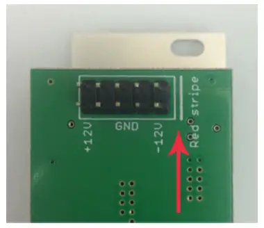
Ensure the 10-pin connector on the power cable is connected correctly to the module before proceeding. The red stripe on the cable must line up with the -12V pins on the module’s power connector. The pins are indicated with the label -12V, a white stripe next to the connector, the words “red stripe”, or some combination of those indicators.
Most modules will come with the cable already connected but it is good to double check the orientation. Be aware that some modules may have headers that serve other purposes so ensure the cable is connected to the right one.
The other end of the cable, with a 16-pin connector, connects to the power bus board of your Eurorack case. Ensure the red stripe on the cable lines up with the -12V pins on the bus board. On Intellijel power supplies the pins are labelled with the label “-12V” and a thick white stripe:
If you are using another manufacturer’s power supply, check their documentation for instructions.
Once connected, the cabling between the module and power supply should resemble the picture below:
Before reconnecting power and turning on your modular system, double check that the ribbon cable is fully seated on both ends and that all the pins are correctly aligned. If the pins are misaligned in any direction or the ribbon is backwards you can cause damage to your module, power supply, or other modules.
After you have confirmed all the connections, you can reconnect the power cable and turn on your modular system. You should immediately check that all your modules have powered on and are functioning correctly. If you notice any anomalies, turn your system off right away and check your cabling again for mistakes.
Connecting Tanks
You can simultaneously connect up to three reverb tanks (available separately) to a Springray2 , and select which to use with the front panel TANK switch. The three tank connections are labelled A, B and C, with the A and B connections located on the back panel and the C connection located on the front.
All three connections feature RCA jacks, and you may plug any tank into any of the three connections (A, B or C). Obviously, if you have room to mount tanks inside your case, you’ll probably find it easiest to connect any internal tanks to the rear panel. Larger tanks, or tanks that you wish to “play” (by plucking, strumming, or e-bowing) should be located outside the case — and are thus easiest to connect to the front panel C connection.
NOTE: Reverb tanks are natural antennas — so locating them inside your case may produce unwanted noise due to their close proximity to various eurorack modules. Often, with a bit of rearranging (of either modules or internal tanks), you’ll be able to find an arrangement in which noise is eliminated.
Each tank requires two connections: Plug a Springray2SEND jack into the INPUT of your reverb tank, and plug the tank’s OUTPUT into the corresponding RTN (return) jack on the Springray2.
Note that all Springray2 SEND jacks are colored white, and all RTN jacks are colored red.
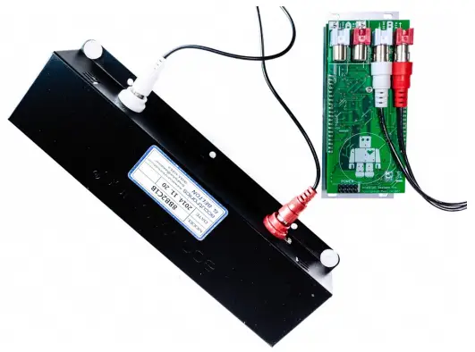
The smallest of the three Accutronics tanks does not come with an RCA connecting cable. Instead, it connects to the Springray2 via two small, keyed connectors on the Springray2 back panel A connector, as shown to the right:
OVERVIEW
There are many excellent digital reverbs available these days but there is still nothing quite like the timeless and magical character of a true spring reverb.
At Intellijel we have a huge love for true analog devices and it has always been important for us to explore as many of these fundamental analog building blocks of synthesis as possible.
In the development of this module we were blown away by how much there is to explore. Each tank has a totally different set of characteristics, and there were many unexpected surprises when feeding it a wide variety of sound sources. One of the most interesting results was how a slow attack saw waveform from a Dixie almost sounds like a realistic cello!
Version two of the Springray provides a number of changes and improvements to the original design. The shelving EQs have been replaced with a parametric EQ with frequency, Q, and gain controls. The CV inputs for feedback and mix balance have been replaced with inputs to control the filter frequency and gain. Lastly, the feedback and limiter circuits have been redesigned, and the drive quality has been improved.
Features
- Parametric EQ with controls for frequency, Q, and gain.
- Feedback path with virtual tube circuitry.
- Redesigned limiter circuit in feedback path to prevent high gain feedback from clipping the output.
- Selector switch to choose between three different connected tanks (one on the front and two on the back).
- Improved drive input with large gain (can overdrive the tank inputs).
- External processors can be inserted into the feedback path via the SEND/RETURN normalled inputs.
- Three different sizes of Accutronic tanks are available.
FRONT PANEL
Controls
 [1] TANK – Selects which of three tanks Springray2 will use. Tank C has its connections on the front of the modules, while Tanks A and B are connected to the back.
[2] FREQ – Sets the frequency of the parametric EQ. Springray2 positions this EQ post-tank in the signal chain, meaning it affects only the wet signal.
[3] GAIN – Adjusts the amount of boost or cut applied by the parametric EQ. No gain is applied when this knob is pointing straight up in the center detent position. Turning the knob counterclockwise results in a frequency cut; turning it clockwise results in a frequency boost.
[4] Q – Determines the width, or Q of the parametric EQ. The higher the Q, the narrower the boosted (or cut) frequency band.
[5] FEEDBACK – Controls the amount of processed signal fed into the feedback path.
[6] LIMITER – Adjusts the threshold of the built-in limiter, which can help reduce the undesired effects of runaway feedback. Fully counterclockwise sets a low limiting threshold, and will thus produce more limiting. Fully clockwise provides a high threshold with little limiting.
[7] GR – Lights if gain reduction is being applied by the limiter.
[8] DRIVE – Adds gain to the input signal.
[9] MIX – Determines the wet/dry balance of the MIX output.
[10] CLIP – Indicates if the signal is clipping. The circuitry monitors several key points throughout the signal chain, and the CLIP indicator lights if any one point clips.
[11] FREQ Attenuator – Controls the amount of modulation sent to the FREQ parameter.
[12] GAIN Attenuator – Sets the amount of modulation sent to the GAIN parameter.
Inputs and Outputs
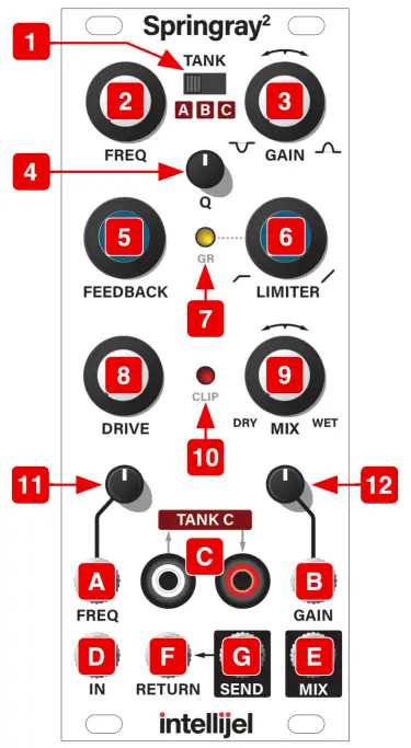 [A] FREQ – Allows an input signal to modulate the FREQ, enabling external voltage control of the parametric EQ frequency.
[B] GAIN – Allows an input signal to modulate GAIN, enabling external voltage control of the parametric EQ’s gain (boost or cut).
[C] TANK C – Send and return jacks connecting an external spring tank. This tank will be used by Springray2 if the TANK switch is set to C.
[D] IN – Provides the input signal for Springray2.
[E] MIX – Outputs a wet/dry balance determined by the MIX knob.
[F] RETURN – Injects an external signal into the feedback path.
[G] SEND – Outputs a fully wet and EQ’d signal.
ARCHITECTURE & USAGE
Below is a basic block diagram illustrating the signal flow through Springray2.
Springray2 uses a feedback path with an asymmetrical FET-based virtual tube distortion circuit, which adds even-order harmonics for a pleasing overtone structure often associated with vacuum tubes.
Although the previous illustration shows a CLIP indicator after the MIX block, Springray2 actually monitors several points along its signal chain, specifically: MIX output; EQ output; AGC input; and the summing circuit where input and feedback are mixed post-driver. If clipping is detected at any of these four points, then the CLIP LED lights.
The SEND and RTN jacks in the feedback path provide numerous opportunities to further shape and control the range of effects. For example:
- SEND outputs a fully wet signal, enabling you to mix wet & dry signals externally. This is useful if you want to modulate the wet/dry balance as part of a patch.
- Patching a VCA into the SEND & RTN jacks gives you the ability to modulate the Springray2 feedback signal by modulating the VCA.
- Patching an external signal processor into the feedback path can alter the sonic characteristics of the feedback signal. Some processors are rather subtle in their effect, but pitch shifters, comb resonators and delays can yield particularly interesting results. Experiment!
report this adUp to three different spring tanks can be connected to Springray2 simultaneously, and the active tank is selected with the TANK switch. Tank C connects to the RCA jacks on the front of the module, while tanks A and B have their connections on the back. Intellijel offers three sizes of tank from Accutronics, each with their own character. The tiny tank is small enough to fit inside many cases and sounds a bit like a resonator. The larger two tanks offer a more familiar spring reverb sound. Connecting multiple tanks gives you instant access to three entirely different flavours of spring reverb in a single module. See Connecting Tanks for more information.
TECHNICAL SPECIFICATIONS
| Width | 10 hp |
| Maximum Depth | 42 mm |
| Current Draw | 44 mA @ +12V34 mA @ -12V |
References
[xyz-ips snippet=”download-snippet”]