![]()
Steppy 1U4-Track 64-Step Programmable Gate Sequencer
ManualFirmware Version: 1.2Revision: 2020.10.26
COMPLIANCE
 This device complies with Part 15 of the FCC Rules. Operation is subject to the following two conditions: (1) this device may not cause harmful interference, and (2) this device must accept any interference received, including interference that may cause undesired operation.
Changes or modifications not expressly approved by Intellijel Designs, Inc. could void the user’s authority to operate the equipment.
Any digital equipment has been tested and found to comply with the limits for a Class A digital device, pursuant to part 15 of the FCC Rules. These limits are designed to provide reasonable protection against harmful interference when the equipment is operated in a commercial environment. This equipment generates, uses, and can radiate radio frequency energy and, if not installed and used in accordance with the instruction manual may cause harmful interference to radiocommunications.
![]() This device meets the requirements of the following standards and directives:
This device meets the requirements of the following standards and directives:
EMC: 2014/30/EUEN55032:2015 ; EN55103-2:2009 (EN55024) ; EN61000-3-2 ;EN61000-3-3Low Voltage: 2014/35/EUEN 60065:2002+A1:2006+A11:2008+A2:2010+A12:2011RoHS2: 2011/65/EUWEEK: 2012/19/EU
INSTALLATION
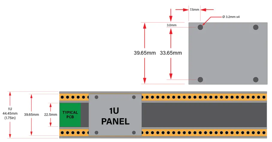
This module is designed for use within an Intellijel-standard 1U row, such as contained within the Intellijel 4U, 7U, and Palette Eurorack cases. Intellijel’s 1U specification is derived from the Eurorack mechanical specification set by Doepfer that is designed to support the use of lipped rails within the industry-standard rack heights.
Before You Start
Intellijel Eurorack modules are designed to be used with a Eurorack-compatible case and power supply. We recommend you use Intellijel cases and power supplies.
Before installing a new module in your case, you must ensure your power supply has a free power header and sufficient available capacity to power the module:
- Sum up the specified +12V current draw for all modules, including the new one. Do the same for the -12 V and +5V current draw. The current draw will be specified in the manufacturer’s technical specifications for each module.
- Compare each of the sums to specifications for your case’s power supply.
- Only proceed with the installation if none of the values exceeds the power supply’s specifications.Otherwise, you must remove modules to free up capacity or upgrade your power supply.
You will also need to ensure your case has enough free space (hp) to fit the new module. To prevent screws or other debris from falling into the case and shorting any electrical contacts, do not leave gaps between adjacent modules, and cover all unused areas with blank panels. Similarly, do not use open frames or any other enclosure that exposes the backside of any module or the power distribution board.
You can use a tool like ModularGrid to assist in your planning. Failure to adequately power your modules may result in damage to your modules or power supply. If you are unsure, please contact us before proceeding.
Installing Your Module
When installing or removing a module from your case always turn off the power to the case and disconnect the power cable. Failure to do so may result in serious injury or equipment damage.
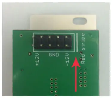
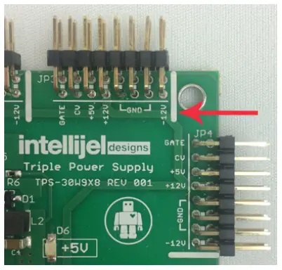
Ensure the 10-pin connector on the power cable is connected correctly to the module before proceeding. The red stripe on the cable must line up with the -12V pins on the module’s power connector. The pins are indicated with the label -12V, a white stripe next to the connector, the words “red stripe”, or some combination of those indicators.
Most modules will come with the cable already connected but it is good to double-check the orientation. Be aware that some modules may have headers that serve other purposes so ensure the cable is connected to the right one.
The other end of the cable, with a 16-pin connector, connects to the power bus board of your Eurorack case. Ensure the red stripe on the cable lines up with the -12V pins on the bus board. On Intellijel power supplies the pins are labeled with the label “-12V” and a thick white stripe:If you are using another manufacturer’s power supply, check their documentation for instructions.
Once connected, the cabling between the module and power supply should resemble the picture below:
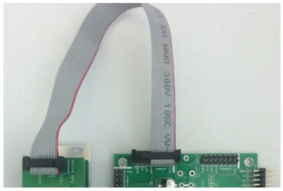
Before reconnecting power and turning on your modular system, double-check that the ribbon cable is fully seated on both ends and that all the pins are correctlyaligned. If the pins are misaligned in any direction or the ribbon is backward you can cause damage to your module, power supply, or other modules.
After you have confirmed all the connections, you can reconnect the power cable and turn on your modular system. You should immediately check that all your modules have powered on and are functioning correctly. If you notice any anomalies, turn your system off right away and check your cabling again for mistakes.
OVERVIEW
Steppy is a 4-track programmable gate sequencer with eight internal memory slots, external clocking, various playback options, and a performance-first design aesthetic.
Each track features numerous parameters that govern its playback independently of the other tracks. Specifically:
- Each track has its own length, which can range from 1-step to 64-steps, allowing for polyrhythms fills or constantly evolving gate interactions between tracks.
- Each track has its own gate length, which ranges from very short to very long, with tied gates possible at the extreme setting.
- Each track has its own clock divider, allowing patterns to play out over completely different periods of time.
- Each track has its own swing setting, which offsets the timing of every other step.
- Each track has its own delay setting, which offsets the timing of every step.
- Each track has its own probability control, which sets the likelihood that each programmed gate will fire when called upon by the pattern.
- Each track can be shifted (or ‘rotated’) forward or backward by a number of steps. So if you’ve created a pattern that ‘feels like it has its downbeat on step 3, you can shift that pattern two steps backward, so that the downbeat sits on step 1.
Tracks can be selected and modified in real-time as the sequence plays. A SELECT button allows you to access each track (and each page of 16 steps within that track) directly through Steppy’s intuitive multifunction buttons array.
Tracks can be individually muted and unmuted, and a special performance mode (called “Loopy”) enables you to touch any two gate steps and instantly create a performance that loops between those steps.
In addition, each step within a track can be assigned a different number of ratchets (repeats), and a special Tap Record mode lets you record patterns in real-time, rather than via a step-recording grid.
Track patterns can be cleared without clearing their playback parameters, and all track patterns (along with their individual playback and performance parameters) can be saved as a preset to one of eight internal memory slots.
QUICK START: CREATE A TRACK
This tutorial is designed to get you up and running with Steppy as quickly as possible. Detailed descriptions of all functions, features, and methodologies appear later in the manual.
Load an Empty Preset First thing’s first. Just so we’re all on the same page, it’s probably a good idea to load an empty preset into Steppy’s active memory. To do so:
- Press the red EDIT button at the bottom left to enter Edit mode.The red Edit Mode LED lights, and any lit multifunction buttons glow red.Edit functions are labeled in the text beneath the bottom row of multifunction buttons.
- Press the LOAD button (bottom-right button).The LOAD button will glow red, and the top row of buttons will be used to select which patch you want to load (and subsequently clear).If a top-row button has a solid red light, it means a preset is stored in that ‘slot.’ The flashing red button indicates the currently loaded preset. If a button isn’t lit, then the ‘slot’ has no preset saved to it.In this next operation, you are going to first load a preset into Steppy’s active memory. You will eventually be clearing (erasing) this preset, so make sure to select one that’s expendable.
- Press whichever of the 8 top-row buttons corresponds to the preset number you wish to load. In this example, we’ll assume you press the first (top-left) button.The buttons will all flash briefly to confirm that you’ve loaded a preset.
- Press and hold the LOAD button (bottom-right) for 1 second (long-press) to clear the contents of the preset.All buttons will flash, and the contents of the loaded preset will be deleted.
- Press the red EDIT button to exit Edit Mode (turning off its red indicator LED) and return to Play Mode.
Connect a Clock & Program a Track
- Connect the output from an external clock module to Steppy’s CLK input.An external clock is needed to make Steppy start stepping. Steppy will advance one stepper clock pulse (unless you use the clock divider feature, discussed later in the manual).Notice that the LED next to the CLK input flashes with each input trigger and that a red button “marches” across Steppy’s 16 multifunction buttons, beginning at the top-left (step 1) and ending at the bottom-right (step 16) before repeating.Notice, also, that the bottom-right button is constantly pulsing green. This indicates it’s the last step in the pattern, which (in this case) means the pattern is 16-steps long. Patterns can be of any length from 1-step up to 64-steps (requiring multiple Pages, which gives you potential insight into some of the panel labels). For now, we’ll stick with the default 16-step pattern length.
- Connect a cable from Steppy’s OUT A jack to another module (such as a trigger input on a drum module or an envelope). In this example, we’re triggering a kick drum sound on an Intellijel Plonk.Each Steppy preset consists of up to four Tracks (A, B, C, and D), each with its own gate output.Because you previously loaded an empty patch, Steppy’s Play Mode defaults to showing and controlling the gates and parameters for Track A.
- Unless you got overly anxious and started pressing buttons already (it happens), then all 16 steps are currently off — meaning no gates are being sent to OUT A. Press one of Steppy’s 16 multifunction buttons to assign a gate to that step. Press another and another.You will see the OUT A LED flash every time Steppy plays a step with a gate. You should also hear the sonic impact of those steps (assuming you’ve got everything patched upright).
- Continue to turn various steps on and off until you’ve got a kick drum pattern you like.
- Next, patch OUT B into a gate or trigger input on another module (such as a snare drum sound on a second Intellijel Plonk).
- Press the black SELECT button in the upper left corner.Its yellow LED lights indicate you’re in Select mode, and the 16 multifunction buttons will now take on different functionality, as indicated by their yellow color.Select Mode functions are indicated by text labels with black backgrounds. Notice the four left buttons in the top row are used for track selection, and that the Track A button is currently lit (indicating Play Mode controls Track A).
- Press the button corresponding to Track B (causing it to light instead of Track A), then press the black SELECT button again to exit Select Mode, and return to Play Mode.
- The 16 multifunction buttons now control Track B, so start punching out patterns for your snare module.
Save the Preset
- Press the red EDIT button at the bottom left to enter Edit mode.Edit functions are labelled in the text beneath the bottom row of multifunction buttons.
- Press the SAVE button (bottom row, second from right).Presets are saved into one of 8 locations, which map to each of the 8 multifunction buttons in the top row. If a button has a solid red light, it means a preset is already saved in that ‘slot,’ and if you select it, you will overwrite that preset. The flashing red button indicates the currently loaded preset, which you are actively modifying. If a button is off, then the preset ‘slot’ is currently empty.
- Decide which of the 8 preset slots you wish to save your work to, and press its corresponding top-row button.All the buttons will flash briefly to confirm that you’ve saved the preset.
Next Step
This has been a very simple and rudimentary tutorial designed only to help you get comfortable with some operational basics and navigation. Steppy features numerous additional techniques for modifying and fine-tuning your tracks, be it through pattern length adjustments; gate length changes; clock division; swing; gate probabilities, or playback and performance features such as the Page Follow (![]() ) and Loopy (
) and Loopy (![]() ) settings. All will be discussed, in-depth, later in thismanual.
) settings. All will be discussed, in-depth, later in thismanual.
So this next tutorial has but a single step:
- Read the rest of the manual.Knowledge is good.
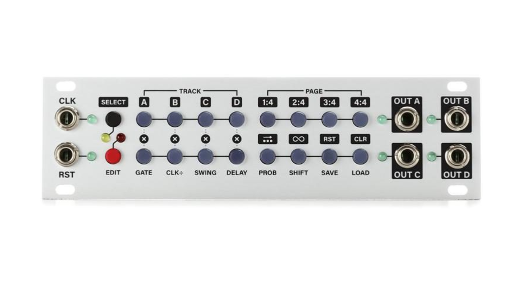
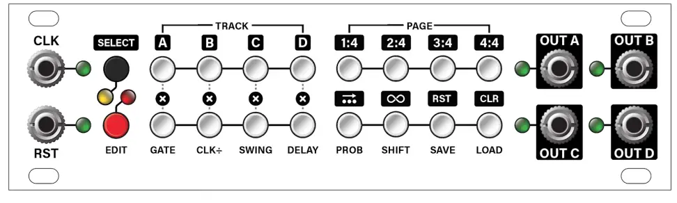
FRONT PANEL
Inputs & Outputs
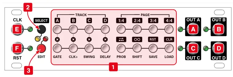
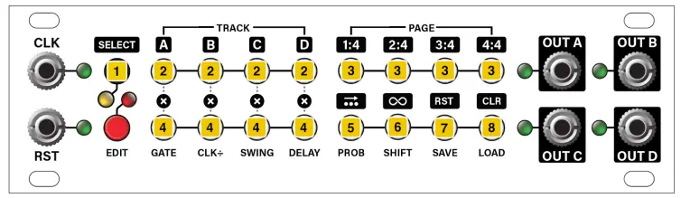
[A] OUT A – Gate output (+5V) for Track A. Corresponding LED lights when the gate is high.[B] OUT B – Gate output for Track B. Corresponding LED lights when the gate is high.[C] OUT C – Gate output for Track C. Corresponding LED lights when the gate is high.[D] OUT D – Gate output for Track D. Corresponding LED lights when the gate is high.[E] CLOCK (CLK) IN – Connect an external clock (or any other trigger source) to this input. Each time the CLK input voltage goes high, the sequence advances one step (unless you’re using the built-in clock divider). The corresponding LED lights every time it detects an input pulse.Note that Steppy will not play without a CLK input.
NOTE: Steppy performs best when driven by a steady clock signal. Syncopated gate sequences or random triggers may result in unpredictable gate lengths, delay settings, swing and ratcheting patterns since these are derived from the Clock input.
[F] RESET (RST) IN – Accepts a trigger or gate, which Steppy interprets in one of two ways:
- RESET Mode: A trigger or gate received at the RST jack resets all patterns (across all four tracks) back to their first step. This is particularly useful if your tracks have different lengths and you wish to re-align them to their first beats. This is the default mode, as shipped from the factory.
- RUN Mode: This is an optional mode, into which you must boot Steppy (see below). As with RESET Mode, a gate received at the RST jack resets all patterns (across all four tracks) back to their first step, but it also enables pattern playback. Specifically, when a gate is high, the patterns play. When a gate is low, they don’t. This lets you remotely start and stop patterns, rather than having them run continuously.
Hold the SAVE RST button on boot up to toggle between RUN and RESET modes (the setting is saved across boots). On the SELECT page, you’ll see the SAVE RST button light yellow if the RUN mode is enabled.
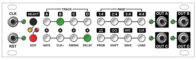
Controls
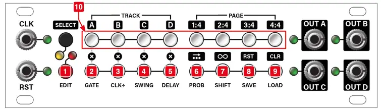
[1] MULTIFUNCTION Buttons – These backlit buttons perform different functions depending on Steppy’s current mode.
- Play Mode: In Play Mode, the buttons set and display gate patterns.Play Mode is indicated when neither the yellow Select Mode nor the red Edit Mode LEDs are lit. You can also tell you’re in Play Mode because (in general) the majority of lit MULTIFUNCTION buttons are GREEN. See Play Mode for detailed information.16 steps are displayed at one time, with steps 1-8 on the top row, and steps 9-16 on the bottom row. Patterns can be up to 64 steps long (spread across 4 pages); and four entirely different patterns can exist simultaneously (in Tracks A-D).A GREEN button indicates that a step is ‘on’ (meaning it will send a gate to the corresponding output). A flashing GREEN button indicates the last step in a sequence (sequences can be any length from 1 to 64 steps). A button turns RED when it’s the active step in a sequence.
- Select Mode: In Select mode, the buttons perform the functions indicated by the labels with black backgrounds.Enter Select Mode by pressing the black SELECT button. In Select mode, the top row of buttons select the current track and page, and the bottom row turns mute on/off for each track, as well as enabling the Page Follow (
 ) function, the performance looping feature (), pattern clearing, and reset.YELLOW buttons indicate the selected Track and Page (top row), as well as the state of the Page Follow () and Loopy () features in the bottom row. Buttons in the bottom row (immediately beneath the four Track buttons) light YELLOW when the corresponding track is Muted.Select Mode is indicated when the yellow Select Mode LED is lit. You can also tell you’re in Select Mode because (in general) most buttons are YELLOW. See Select Mode for detailed information.
 - Edit Mode: In Edit Mode, the buttons select and modify various parameters, as indicated by the labels beneath the bottom row of buttons.Enter Edit Mode by pressing the red EDIT button. In Edit mode, the bottom row of buttons select which parameter you wish to edit (GATE, CLK ÷, etc), and the top row of buttons set its value. In general, the leftmost button in the top row sets the minimum value for a
parameter and the rightmost button sets the maximum value, with interim values spread across the middle six buttons.Buttons are RED in Edit Mode, with the red button in the bottom row indicating the active parameter and the lit button(s) in the top row indicating the parameter value.Edit Mode is indicated when the red Edit Mode LED is lit. You can also tell you’re in Edit Mode when (in general) most buttons are RED. See Edit Mode for detailed information.
[2] SELECT button – This button turns Select Mode on and off.In Select Mode, the MULTIFUNCTION buttons perform the tasks indicated by the labels with black backgrounds (visually linking them with the black color of the SELECT button). The yellow LED next to the SELECT button turns on when Select Mode is on.
If pressed and released, the SELECT button functions as a toggle button — putting Steppy intoSelect Mode, where it remains until the SELECT button is pressed again to exit Select Mode.
If pressed and held, the SELECT button functions as a momentary switch — temporarily putting Steppy into Select Mode while you press the desired MULTIFUNCTION button. Releasing both the SELECT button and the MULTIFUNCTION button automatically exits Select Mode. This is great if you want to make quick on-the-fly changes. For example, if you’re currently viewing Track A and you want to view Track B, simply press and hold the SELECT button while pressing the “Track B” MULTIFUNCTION button. Release both buttons and Steppy returns to Play mode (which now shows the pattern for Track B) without remaining in Select mode.
[3] EDIT button – This button turns Edit Mode on and off.Edit Mode uses the bottom row of MULTIFUNCTION buttons to select which parameter to edit (as indicated by the labels below the bottom buttons, such as GATE, CLK ÷, SWING, etc). Edit Mode uses the top row of MULTIFUNCTION buttons to adjust the selected parameter value (with, in general, the ‘lowest’ possible value corresponding to the leftmost button, and the ‘highest’ possible value corresponding to the rightmost button).
When Steppy is in Edit Mode, it lights the red LED adjacent to the EDIT button.
Long-press ( > 1 sec) the EDIT button to enable a special Step Edit Mode, which allows ratcheting, along with per-step editing of Gate Length, Step Delay, and Probability.
REFERENCE
The following sections discuss Steppy’s various modes and the function of the buttons within those modes.
Play Mode
Play Mode is Steppy’s default mode. In-Play Mode, the sixteen Multifunction buttons are used to program and display gate patterns, and are lit green when a gate is “on.” In-Play Mode, neither the yellow LED next to the SELECT button nor the red LED next to the EDIT button are lit.
Steppy can play back up to four tracks simultaneously (labeled A, B, C, and D, and which appear at the A, B, C, and D outputs). Each track contains a pattern with an independently assignable length (up to 64-steps), along with several additional playback and performance parameters.
Steppy requires an external clock source (patched into the CLK input) to run and will advance one step for each pulse it receives (unless the clock is divided, as described later).
With Steppy in Play Mode and a clock sent to its input, Steppy will step through each step and playback all four tracks, though the multifunction buttons can display only one track pattern at a time (and only in 16-step blocks, called Pages). The Track displayed in Play Mode is selected using the TRACK and PAGE buttons are discussed in Select Mode.
In-Play Mode (and with an incoming clock driving playback), the RED button steps left-to-right across the top row of buttons, then left-to-right across the bottom row of buttons to indicate the current position within the pattern. Gates can be turned on or off by pressing their respective buttons, with a GREEN button indicating the presence of a gate.
NOTE: If there is no CLOCK input (or if the clock is very slow), and the RED position button is currently lit on a step for which you’re trying to set a gate, you can tell whether or not a gate is present by whether the RED button glows steady (no gate present) or flashes RED / GREEN (gate is present).
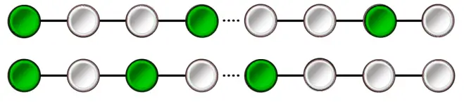
You can set the length of the pattern by long-pressing (>1 sec) the button you wish to be the final step in the pattern. Steppy indicates the pattern length by pulsing (in YELLOW ) the button that corresponds to the final step in the pattern. Gates that are contained within the chosen pattern length glow GREEN, while gates that are outside the length of the current pattern glow YELLOW.
The following illustrations show identical patterns; but in the top example, the track length is set to 16-steps, and in the bottom example, it’s set to 5-steps:
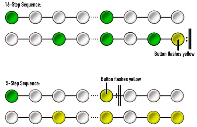
Track patterns can be as long as 64-steps. To create patterns that are longer than 16-steps, use the PAGE Select options (as discussed in Select Mode ) to navigate to the page that contains the desired final step, then long-press the desired step button. For example, if you wanted a 32-step pattern, hold the SELECT button while you press the PAGE 2:4 button (which changes Steppy’s display to the second page of steps, numbered 17-32). Long-press (>1 sec) the right-most button inthe bottom row to set the Track length to 32-steps.
NOTE: If a Track has multiple pages (meaning it’s more than 16-steps), then you can choose whether or not you want Steppy to automatically update its page view such that the currently playing gate is always visible, or if you want the display to remain on a particular page. This is done with the Page Follow ( ![]() ) function, described later.
) function, described later.
Select Mode
In Select Mode, the Multifunction buttons are used to select tracks for viewing & editing; to select pages within those tracks, and for enabling/disabling various track display and performance options.
Note: Steppy can be in both Select mode ( yellow LED) and Edit mode ( red LED) simultaneously. If you’re currently in Edit Mode (discussed later), you can enter Select mode to select which track you wish to edit.
[1] SELECT buttonPress this button to put Steppy into Select Mode. The yellow LED next to the SELECT button turns on when Select Mode is on. In Select Mode, the labels with the black backgrounds correspond to the buttons’ functions (matching the black color of the SELECT button).
If pressed and released, the SELECT button functions as a toggle button — putting Steppy into Select Mode, where it remains until the SELECT button is pressed again to exit Select Mode.
If pressed and held, the SELECT button functions as a momentary switch — temporarily putting Steppy into Select Mode while you press the desired Multifunction button. Releasing both the SELECT button and the Multifunction button automatically exits Select Mode. This is great if you want to make quick on-the-fly changes. For example, if you’re currently viewing Track A and you want to view Track B, simply press and hold the SELECT [1] button while pressing the TRACK B [2] button. Release both buttons and Steppy returns to Play mode (which will now be showing the pattern for Track B) without remaining in Select mode.
[2] TRACK buttonsWhen in Select mode, these four buttons select which of the four tracks (A, B, C or D) you wish to display/edit. A yellow button indicates the selected track.
[3] PAGE buttonsWhen in Select mode, these four buttons select which of the four pages (1, 2, 3, or 4) you wish to display/edit. Each page displays 16 steps at a time, meaning there are a total of 64 available steps per pattern. A yellow button indicates the selected page. A flashing yellow button indicates that the pattern’s last step is on that page.
[4] MUTE buttonsWhen in Select mode, these four buttons function as Track Mutes for the track immediately above it. In other words, the left-most button mutes/unmutes Track A; the next-to-left button mutes/unmutes Track B; etc. When a Track is muted, the corresponding Mute button turns yellow.
[5] PAGE FOLLOW button (![]() )When in Select mode, press this button to enable the Page Follow function. Page Follow is on when the button glows yellow.
)When in Select mode, press this button to enable the Page Follow function. Page Follow is on when the button glows yellow.
If Steppy is in Play mode and currently playing a Track that extends across multiple pages (that is, it’s longer than 16 steps), then activating Page Follow allows Steppy to update its display to “follow” the page changes.
NOTE: If you’re in Select mode and you press a Page button to select a page, Steppy will automatically turn off the Page Follow function, enabling to you make the desired changes to the selected page.
[6] LOOPY button (![]() )When in Select mode, press this button to enable the performance looper feature (“Loopy”).When Loopy is active, its button glows yellow.
)When in Select mode, press this button to enable the performance looper feature (“Loopy”).When Loopy is active, its button glows yellow.
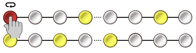
When Loopy is activated, Steppy gives you the ability to loop small segments of a larger pattern when you’re back in Play mode. Specifically, playback will loop between any two buttons you hold while in Play mode. If you hold only a single button-down, that single step will repeat until you release the button. When Loopy is active, the yellow Select LED and red Edit LED to flash rapidly back-and-forth. If Loopy is active and you hold a pair of buttons in Play mode (to create a loop), the gates within the loop will have green buttons, and gates outside the loop will have yellow buttons.
For example, assume this is your current pattern:
If Loopy (![]() ) is active, pressing one button loops playback of that single step, repeating it over and over for as long as you hold the button. The button is red because red indicates the current playback position, which is endlessly repeated on a single step. The other buttons are yellow indicating they are programmed into the pattern but are not within the currently playing loop:
) is active, pressing one button loops playback of that single step, repeating it over and over for as long as you hold the button. The button is red because red indicates the current playback position, which is endlessly repeated on a single step. The other buttons are yellow indicating they are programmed into the pattern but are not within the currently playing loop:
If Loopy (![]() ) is active, pressing two buttons loops playback between those steps, inclusive of the buttons you hold. So in the following example, Steps 1-4 loop for as long as you hold the buttons. Again, buttons outside the currently playing loop are yellow to indicate they are programmed into the pattern but are not within the currently playing loop:
) is active, pressing two buttons loops playback between those steps, inclusive of the buttons you hold. So in the following example, Steps 1-4 loop for as long as you hold the buttons. Again, buttons outside the currently playing loop are yellow to indicate they are programmed into the pattern but are not within the currently playing loop:
The standard Track position continues to advance normally as a loop plays. This means, when you release the buttons, the pattern reverts to playing exactly the step it would have played had you not looped a section.
All edited track parameters (Swing, Delay, Probability, etc) are respected when looping, and looping applies to all tracks when engaged.
To latch Loopy playback :
- While holding down the two buttons that define the length of the Loopy sequence, short-press the SELECT button.You can now release your hold on the two buttons since pressing the SELECT button during Loopy playback latches it.
- Press any of the step buttons to unlatch the Loopy function, and return to normal playback.
[7] RESET buttonWhen in Select mode, press this button to reset all patterns (across all four tracks) back to their first step. This is particularly useful if your tracks have different lengths and you wish to re-align them to the first beat. This button replicates the functionality of the RST input jack. Pressing the RESET button causes all 16 buttons to briefly flash green — indicating the reset operation has occurred.
If Steppy is in RUN Mode (see the RESET (RST) IN jack description in Inputs & Outputs ), then the button is lit yellow to indicate that Steppy is in RUN mode.
PANIC feature: In Select mode, if you long-press the RESET button (i.e hold the RESET button for >1 second), you’ll send a gate off to all the outputs. This is useful in the unlikely event that one of the outputs gets stuck “on” when Steppy’s input clock is stopped or removed.
[8] CLEAR buttonWhen in Select mode, the button performs two different functions depending on how long it’s held down. Specifically;
- Short-press (button pressed and quickly released): Short-press the CLEAR button to clear all steps from the active track (turning all gates off). This causes all 16 buttons to briefly flash red — indicating that the gates have been cleared. Short-pressing the CLEAR button only clears the trigger pattern from a Track. Any track parameters (such as Gate Length, Clock Division, or Probability) remain part of the track and will affect any new pattern you create.
- Long-press (button pressed and held for 1-second): Press and hold the CLEAR button for 1 second to clear the entire contents of a Track, meaning its gate pattern plus all its Track parameters (such as Gate Length, Clock Division, and Probability).
Edit Mode
In Edit Mode, the Multifunction buttons select and modify various parameters (such as gate length, clock division, swing, etc.), as indicated by the labels beneath the bottom row of buttons. The red LED next to the EDIT button turns on when Edit Mode is on.
Note: Steppy can be in both Select mode ( yellow LED) and Edit mode ( red LED) simultaneously. If you’re currently in Edit Mode, you can enter Select mode to select which track you wish to edit.
[1] EDIT buttonShort-press (< 1 sec) this button to put Steppy into Edit Mode. The red LED next to the EDIT button turns on when Edit Mode is on.
Edit Mode uses the bottom row of multifunction buttons to select which parameter to edit (as indicated by the labels below the bottom buttons, such as GATE, CLK ÷, SWING, etc). Edit Mode uses the top row of buttons [10] to modify the selected parameter value (with, in general, the ‘lowest’ possible value corresponding to the leftmost button, and the ‘highest’ possible value corresponding to the rightmost button).
Long-press ( > 1 sec) the EDIT button to enable a special Step Edit Mode, which allows ratcheting, along with per-step editing of Gate Length, Step Delay, and Probability.
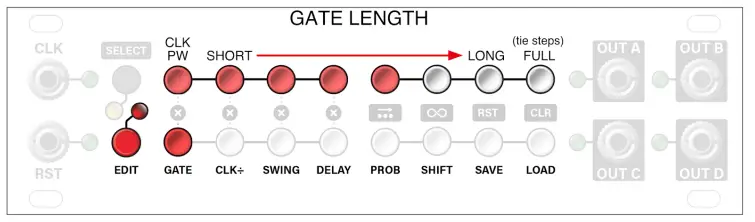
[2] Gate Length (GATE) buttonWhen in Edit mode, press this button to edit the gate length for all steps in the selected Track (each track has its own gate length setting). Gate Length editing is available when the GATE button glows red.
When editing gate lengths, the top row of buttons sets the actual length. The leftmost buttons pin the gate length to the width of the input pulse; the rightmost button makes a gate last the full width of the step (allowing for ties). Middle values result in steadily increasing gates of fixed length, with the shortest gates occurring toward the left, and growing increasingly longer as you move to the right.
To set the Gate Length for the selected track, simply press the top row button corresponding to the desired value. If you long-press (>1 sec) the value button, you apply the Gate Length setting to all four tracks simultaneously.
In the following example, the Gate Length is set to a value slightly more than halfway between “short” and “long.”
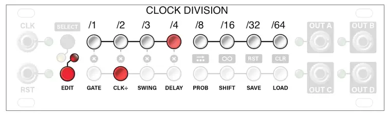
[3] Clock Division (CLK ÷) buttonWhen in Edit mode, press this button to edit the clock rate at which the selected track plays (each track has its own clock division). The playback speed is expressed as a division of the input CLK. Clock Division editing is available when the CLK ÷ button glows red.
When editing clock divisions, the top row of buttons sets the actual division, with no clock division (/1) occurring at the leftmost button, and /64 occurring at the rightmost (meaning the sequence advances one step for every 64 CLK input pulses).
To set the Clock Division for the selected track, simply press the top row button corresponding to the desired value. If you press and hold the value button (long-press), you apply the Clock Division setting to all four tracks simultaneously.
In the following example, the clock division is set to /4 (meaning the sequence advances one step for every 4 CLK input pulses).
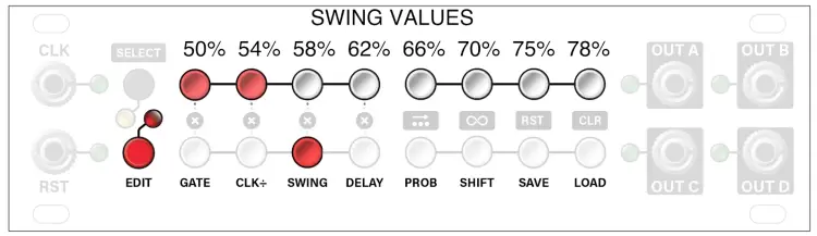
[4] SWING buttonWhen in Edit mode, press this button to edit the swing percentage for the selected Track (each track has its own swing rate). Swing options conform to MPC “standard” (with the addition of 78%), and apply the delay to every other step in a pattern (thus, causing it to ‘swing’). Swing editing is available when the SWING button glows red.
When editing swing values, the top row of buttons set the values from 50% (no swing) on the leftmost button, to 78% swing on the rightmost button.
To set the Swing amount for the selected track, simply press the top row button corresponding to the desired value. If you press and hold the value button, you apply the Swing setting to all four tracks simultaneously.
In the following example, Swing is set to 54%.
 NOTE: If a track employs both a Swing amount and a Delay amount (discussed below), those delays will be summed. Gate lengths are maintained, however, if a step is swung and/or delayed so much that the requested gate length would overlap into the next step, then Steppy automatically shortens the gate to ensure every step triggers.
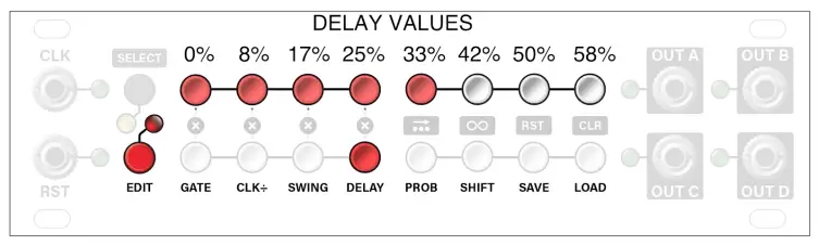
[5] DELAY buttonWhen in Edit mode, press this button to edit the amount of delay to apply to every step in a track. Unlike Swing, which delays every other step, the delay parameter causes every step to lag behind the clock at the selected rate. Delay editing is available when the DELAY button glows red.
When editing delay values, the top row of buttons sets the amount all steps are delayed (in percent). That is, delay options range from 0% (no delay) on the leftmost button to 58% delay on the rightmost button.
To set the Delay amount for the selected track, simply press the top row button corresponding to the desired value. If you press and hold the value button (long-press), you apply the Delay setting to all four tracks simultaneously.
In the following example, Delay is set to 33%.
NOTE: If a track employs both a Delay and Swing (discussed above), those offsets will be summed. Gate lengths are maintained, however, if a step is swung and/or delayed so much that the requested gate length would overlap into the next step — then Steppy automatically shortens the gate to ensure every step triggers.
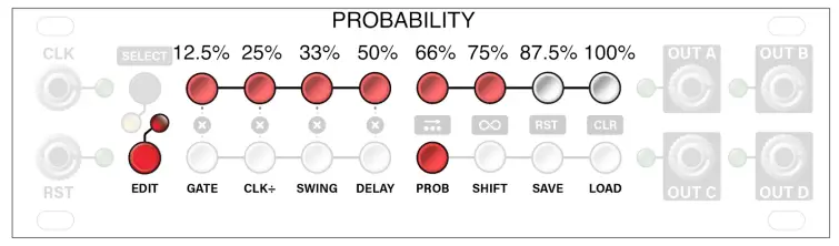
[6] Probability (PROB) buttonWhen in Edit mode, press this button to set the probability that any step within the pattern will actually play when requested. Probability editing is available when the PROB button glows red.
When editing probability values, the top row of buttons sets the probability percentage. Pressing buttons toward the left result in a low probability; pressing buttons to the right result in a higher probability that any programmed step will play. The rightmost button (100%) is the default. This means your pattern will play exactly as programmed every single time.
To set a Probability for the selected track, simply press the top row button corresponding to the desired value. If you press and hold the value button, you apply the Probability set to all four tracks simultaneously.
In the following example, the probability is set to 75%. That means each step in the track has a 75% chance of playing. This means, on average, each step will play 3 out of the 4 times you programmed it to play.
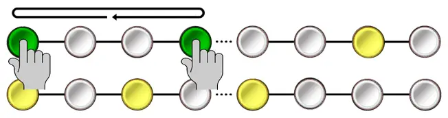
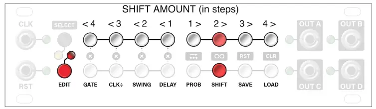
[7] SHIFT buttonWhen in Edit mode, press this button to enable pattern shifting. Pattern shifting allows you to rotate the active pattern forward or backward by a specified number of steps. Pattern shifting is available when the SHIFT button glows red.
When shifting patterns, the top row of buttons sets the amount of shift (by step). The further a button is left-of-center, the more the pattern will shift to the left (up to 4 steps). The further a button is right-of-center, the more the pattern will shift right (up to 4 steps). When you press a button in the top row to set a shift amount, the display will flash rapidly (the same number of times as the shift amount) to confirm the shift has occurred.
To set a Shift amount for the selected track, simply press the top row button corresponding to the desired value. If you press and hold the value button (long-press), you apply the Shift to all four tracks simultaneously.
In the following example, pressing the 2 > button shifts the pattern to the right by two steps, meaning any gate that was once assigned to step 1 is now assigned to step 3 (1+2); any gate that was once assigned to step 2 is now assigned to step 4 (2+2), etc…
NOTE: Pattern shifting only affects those steps included within the programmed track length.For example, if a pattern is 16-steps long, the pattern shift will affect only those 16-steps.Steps 17-64, because they are not active, will not be shifted.
[8] SAVE buttonWhen in Edit mode, press this button to enable Preset saving. Steppy can store up to 8 presets (assigned to each of the 8 buttons in the top row of multifunction buttons). A preset contains the settings assigned to all 4 tracks, plus the patterns within those tracks (as shown in Steppy Architecture, later in this manual).
To save a preset:
- Press the red EDIT button to enter Edit mode.
- Press the SAVE button.The SAVE button glows red and the top row of buttons lights, displaying the status of the eight presets:• Lit Preset button: a preset already exists on that button.• Unlit Preset button: there is no preset assigned to that button.• Rapidly Flashing Preset button: indicates the currently active preset.
- Press one of the 8 buttons in the top row to save the preset to that location.
- All buttons will flash quickly to indicate that the preset has been saved.
[9] LOAD buttonWhen in Edit mode, press this button to enable Preset loading. Steppy can store up to 8 presets (assigned to each of the 8 buttons in the top row of multifunction buttons), and the Load function lets you choose which of these to load into active memory for performance.
To load a preset instantly:
- Press the red EDIT button to enter Edit mode.
- Press the LOAD button.The LOAD button glows red and some of the buttons light in the top row to display the status of the eight presets.• Lit Preset button: a preset exists on that button.• Unlit Preset button: there is no preset assigned to that button, and thus nothing to load.• Rapidly Flashing Preset button: indicates the currently active preset.
- Short-press (< 1 sec) one of the 8 buttons in the top row to instantly load it.All buttons will flash quickly to indicate that the preset has been loaded and is now active (further indicated by the fact that the button corresponding to the loaded preset is now flashing rapidly).
To delay loading of a preset until the start of the next cycle :
- Press the red EDIT button to enter Edit mode.
- Press the LOAD button.The LOAD button glows red and some of the buttons light in the top row to display the status of the eight presets, as outlined previously.
- Long-press ( > 1 sec) one of the 8 buttons in the top row.All buttons will flash quickly to indicate that the preset request has been received.However, the new preset will not load until the current pattern completes the cycle on Track 1.
To delete a preset from memory:
- Press the red EDIT button to enter Edit mode.
- Short-press (< 1 sec) the LOAD button followed by the top-row button corresponding to the preset you want to delete.This loads that preset into active memory (as indicated by the rapidly flashing button).
- Long-press (> 1 sec) the LOAD button. All buttons will flash, and the contents of the previously selected preset will be deleted.
NOTE 1: To erase ALL presets from memory, turn off Steppy, then long-press the LOAD button while you power it back on.
NOTE 2: If you power Steppy off and back on, it will reload that last saved or loaded preset — it does not retain any unsaved pattern or track changes. So remember to always save your work if you wish to return to it later.
[10] Value buttonsUse this top row of buttons to set values for the parameters you select with the bottom row of buttons. In general, this row behaves like a horizontal value slider, with lower values to the left and higher values to the right. The specific values assigned to each button depend on the parameter being edited, and these exact values are detailed under each parameter button’s description, above.
Step Edit Mode
Unlike the normal Edit Mode, which applies parameters globally across all steps in a track, Step Edit Mode enables you to modify certain parameters on a step-by-step basis. Specifically, you can edit Gate Length, Delay and Probability on a per-step basis, as well as assign ratchets to individual steps.To edit a parameter on a per-step basis:
- From the default PLAY mode, select the Track and Page you wish to edit (using techniques previously discussed), then long-press ( > 1 sec) the EDIT button to enter Step Edit mode.The EDIT LED will light, and four of the Edit Mode buttons will flash red. These indicate the fourparameters you can set on a per-step basis:• GATE : Sets a step’s Gate Length• CLK ÷: Sets number of Ratchets on a step (see Ratcheting )• DELAY: Sets a step’s Delay• PROB: Sets a step’s Probability
- Press one of the flashing four buttons to edit the corresponding parameter on a per-step basis.That button will flash yellow and any steps with a per-step edit already assigned to it will light up red. The current position is displayed by a green LED (which advances through the pattern if Steppy is running).
- Press whichever of the 16 multifunction buttons corresponds to the step you wish to edit. This puts you into the step’s Parameter Edit mode.If you pressed buttons 1-8, you will then use the bottom row of buttons to set the parameter value for that step (using the same methodology discussed previously for the Edit Mode description of the GATE, DELAY, and PROB parameter settings). If you pressed buttons 9-16, then you’ll set that step’s parameter value using the top row of buttons.NOTE: Ratchets are set using the CLK ÷ button, and are described further in Ratcheting, later in this manual.
- Once you’ve set the desired value for a step, press the same multifunction (step) button to back up one level, exiting the step’s Parameter Edit mode.
- Edit additional steps by pressing the desired multifunction (step) button; setting its value using the buttons in the opposite row, then re-pressing the same multifunction (step) button to exit the Parameter Edit mode.TIP: You can copy one step’s value to another by holding down the stop button you want to copy while pressing the step button to which you want to paste it.
- To exit Step Edit mode, long-press the EDIT button again.NOTE: When you assign a step’s parameter value to the lowest option, it will instead defer to the track’s global parameter value for that step, rather than use the minimum parameter value. For example, no matter what the track’s global probability value is set to, you can override that value on individual steps by pressing any of the row’s right-most 7 buttons (which correspond to 33, 50, 66, 75, 87.5, and 100% probability). However, if you press the first parameter value (12.5% in this case), then the step uses the track’s global probability setting rather than 12.5%.
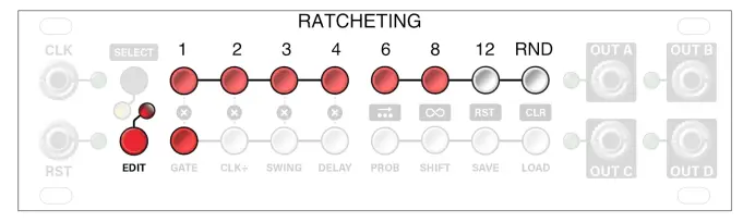
RatchetingSteppy’s ratcheting function is accessed in Step Edit Mode by pressing the flashing CLK ÷ button.
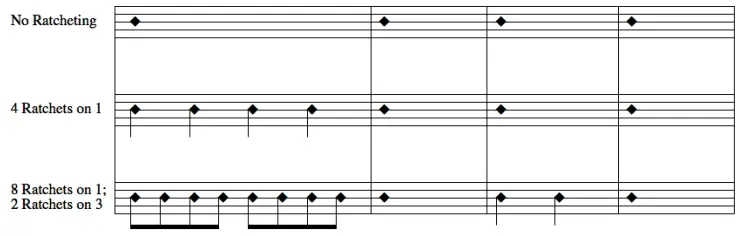
In a normal (non-ratcheting) operation, each step in a sequence fires off a single gate. Ratcheting occurs when one or more of those steps fires off multiple gates before the next step. Each step in a pattern can be programmed to trigger as many as 12 gates in a single step, and each step can have a different number of ratchets (repeats).
The following example illustrates a 4-step pattern. The top line shows how the pattern plays without ratcheting. In the second line, step 1 has been set to ratchet four times. In the bottom line, step 1 has been set to ratchet eight times, and step 3 to ratchet two times.
To Create and Edit Ratchets:
- From the default PLAY mode, select the Track and Page you wish to edit (using techniques previously discussed), then long-press ( > 1 sec) the EDIT button to enter Step Edit mode.The EDIT LED will light, and four of the Edit Mode buttons will flash red.
- Press the flashing CLK ÷ button.It will flash yellow and any steps already containing ratchets will light up red. The current position is displayed by a green LED (which advances through the pattern if Steppy is running).
- Press whichever of the 16 multifunction buttons corresponds to the step you wish to ratchet.This puts you into the step’s Ratchet Assignment mode.If you pressed buttons 1-8, you will then use the bottom row of buttons to set the number of ratchets. If you pressed buttons 9-16, you’ll use the top row of buttons to set the number of ratchets.In this example, we pressed the bottom-left button, which corresponds to step 9, so the top row of buttons will be used to assign the number of ratchets.Ratchets range from 1 (no ratcheting, at the far left); to 2, 4, 6, 8, 12, and random (every pass produces a random number of ratchets). In the following illustration, we have assigned eight ratchets to step 9.
- Once you’ve set the number of ratchets for a step, press the same multifunction (step) button to back up one level, exiting the step’s Ratchet Assignment mode.
- Add ratchets to additional steps by pressing the desired multifunction (step) button; setting the number of ratchets using the buttons in the opposite row, then re-pressing the same multifunction (step) button to exit the Ratchet Assignment mode for that step.TIP: You can copy one step’s ratchet value to another by holding down the stop button you want to copy while pressing the step button to which you want to paste it.
- When you’re done entering or editing ratchets, long-press ( > 1 sec) the EDIT button to exit Step Edit mode.The red Edit LED stops blinking and Steppy returns to Play mode.SHORTCUT: After assigning ratchets to a step, you can press another step button in that same row to edit its ratchets without needing to back out of Ratchet Assignment mode. For example, if you created ratchets on Step 9, you could press any of Steps 10-16 to then edit those ratchets.NOTE: Ratcheting automatically makes the step’s Gate length equal to 1 “tick” (a clock pulse is divided into 24 ticks).
Tap Recording
Tap Recording is a special, alternate way to program trigger patterns into Steppy. Instead of manually turning steps on/off in a grid, Tap Recording lets you tap out your rhythms in real-time.Tapped recordings always play back in sync with the clock input (using whatever Clock Division, Gate, Probability, Ratchets, and any other settings you’ve currently assigned to a Track.
To enter TAP Recording Mode:
- Hold the SELECT button while pressing the EDIT button.The yellow SELECT LED and red EDIT LED will pulse slowly in unison.
To exit TAP Recording Mode:
- If currently in TAP Recording Mode (both LEDs pulsing), press the EDIT button to exit the mode.
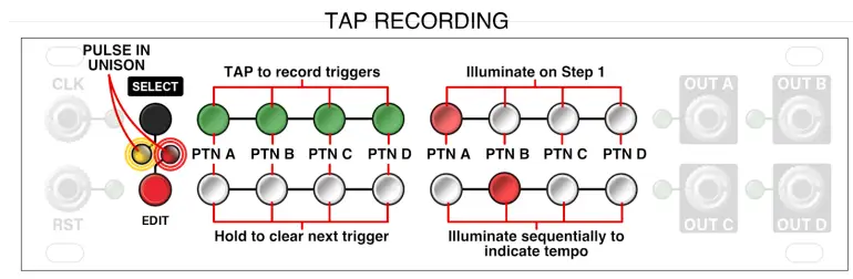
To use TAP Recording Mode:Each of the four buttons on the top-left corresponds to the four-track patterns (A, B, C, and D). With a CLK signal at the CLK input, tap these buttons to record trigger patterns in real-time into the corresponding track.
NOTE: You can choose whether or not you want to hear the triggers as you enter them by pressing the PROB button. Muted taps are indicated by yellow ABCD buttons.
Each of the four buttons on the lower-left also corresponds to the four-track patterns (A, B, C, and D). Only in this case, pressing a button clears any trigger assigned to the next step. To clear multiple steps, hold the button down. The longer you hold the button, the more steps you clear (you can even clear an entire pattern this way).
Each of the four buttons on the upper-right illuminate when the corresponding Track plays Step 1 of its pattern. The four buttons on the bottom-right light sequentially provide a visual indication of the incoming clock (tempo).
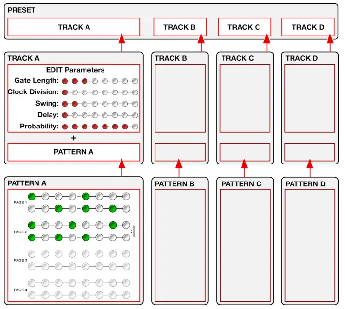
STEPPY ARCHITECTURE
 STEPPY ARCHITECTURE
The following diagram illustrates the architecture of a Steppy preset:
Copying Patterns
You can copy the pattern from one track to another (without copying its edit parameters). To do so:
- Press the SELECT button to enter Select Mode.
- Hold the button corresponding to the track you want to copy from (A, B, C or D).
- While holding the source track’s button, press the button corresponding to the track you want to copy to (A, B, C, or D).The display flashes rapidly.
- Release both buttons.You have now copied the pattern from one track to another. Note that this only copies that pattern itself. Various edited parameters (such as Swing, probability, etc) are not copied.
Copying Pages
Similar to the way you can copy patterns from one track to another (described above), you can also copy from one Track Page to another. Copying pages is useful if, for example, you originally created a one-page pattern, decide to extend its length to two pages, and wish to copy the pattern from the original page to the second page.
- Press the SELECT button to enter Select Mode.
- Hold the button corresponding to the page you want to copy from (1, 2, 3, or 4).
- While holding the source page’s button, press the button corresponding to the page you want to copy to (1, 2, 3, or 4).The display flashes rapidly.
- Release both buttons.You have now copied the pattern from one page to the other.
NOTE: Copying pages does not automatically extend the pattern length. For example, if you have a one-page pattern that ends on Step 16, copying Page 1 to Page 2 will not automatically extend the pattern length to 32 bars. If you wanted the pattern to now play for 32 steps, go to Page 2 (by holding down the SELECT button while clicking the PAGE 2 button), then long-press (>1 sec) the 16th button (bottom-right) to define that step as the “final step” in the pattern. In this case, because we’re on Page 2, the 16th button corresponds to Step 32.
FIRMWARE
Firmware updates, if available, are contained within the latest Intellijel Firmware Updater application, which you can download from the product’s page on the Intellijel.com website. The application is available in both Macintosh and Windows formats and will install firmware into your module over USB. Use the drop-down lists at the top of the application to select the product you wish to update and the firmware version you want to install. Click the Instructions button to read specific instructions for updating your module.
Steppy displays the current version number during start-up. Specifically, the top row of buttons indicates the first digit in the FW version, and the second row of buttons indicates the second digit. For example, if Steppy was running firmware version 2.4, then it would light the second button in the top row and the fourth button in the bottom row, as shown below:
1U / 3U Toggle
 1U / 3U Toggle
Steppy’s 1U and 3U versions run the same firmware, which supports both button orientations. The correct orientation is loaded at the factory, and any subsequent firmware updates will retain the correct orientation. However, if you one day find your Steppy 1U operating as if all the button functions are inverted, it means the 3U orientation is running, instead. To switch back to the 1U orientation, simply hold the SELECT button at startup, and the orientation will toggle back to the 1U layout.
Firmware Change Log
1.20 (2020-01-10)
- NEW FEATURE: Latching Loopy mode. When holding down buttons to define the Loopy steps, press the SELECT button to Latch your loop. Press a step button to unlatch it. If you change your Loopy steps, you will need to press SELECT to latch them again.
- NEW FEATURE: Delayed load. When on the LOAD page, long-press the desired preset button to delay it from loading until the current pattern completes the cycle on Track 1.
- NEW FEATURE: Muted tap entry mode. When in TAP Recording Mode, you can press the PROB button to toggle the muting of your taps. The ABCD buttons will turn yellow when muted.
- NEW FEATURE: Step Edit Mode. Previously, only ratchets could be edited on a per-step basis, but now Gate, Delay, and Probability (along with ratchets) can also be edited using the new Step Edit Mode, accessed by long-pressing the EDIT button. For full details, see Step Edit Mode.
- FIX: Track Probability is now applied to the current position, and will not randomize individual ratchets.
1.11 (2019-10-10)
- FIX Additional filtering on Clock input to handle imprecise clock pulses.
1.10 (2019-08-14)
- NEW FEATURE: RUN Mode (as an alternate to RESET Mode).In RUN Mode, the sequencer will only advance when the RST input has a high gate. In this mode, Steppy will also reset when the gate goes high.Hold the SAVE
RSTbutton on boot up to toggle between RUN and RESET modes (the setting is saved across boots). On the SELECT page, you’ll see the SAVERSTbutton light yellow if the RUN mode is enabled.This feature is discussed in the RESET (RST) IN jack description in the Inputs & Outputs section of this manual. - FIX: In either RUN or RESET mode, any gate that arrives at the RST jack a few milliseconds after the rise of a clock pulse (i.e. when the clock is still high) is automatically compensated for, allowing step 1 to fire immediately.
- FIX: Manually pressing RST from the SELECT page will now immediately reset to step one rather than waiting for the next clock pulse.
V1.00 (2018-10-18)
- Initial release
TECHNICAL SPECIFICATIONS
| Width | 28 hp |
| Maximum Depth | 29 mm |
| Current Draw | 15 mA @ +12V I <1 mA @ -12V |
 report this ad
Steppy 1U Manual
References
[xyz-ips snippet=”download-snippet”]