intellijel Switched Mult 1U Chainable Passive Switched Multiplier User Manual
COMPLIANCE
This device complies with Part 15 of the FCC Rules. Operation is subject to the following two conditions: (1) this device may not cause harmful interference, and (2) this device must accept any interference received, including interference that may cause undesired operation.
Changes or modifications not expressly approved by Intellijel Designs, Inc. could void the user’s authority to operate the equipment.
Any digital equipment has been tested and found to comply with the limits for a Class A digital device, pursuant to part 15 of the FCC Rules. These limits are designed to provide reasonable protection against harmful interference when the equipment i s operated i n a commercial environment. This equipment generates, uses, and can radiate radio frequency energy and, i f not installed and used i n accordance with the instruction manual, may cause harmful interference to radio communications.
![]()
This device meets the requirements of the following standards and directives:
EMC: 2014/30/EUEN55032:2015 ; EN55103-2:2009 (EN55024) ; EN61000-3-2 ; EN61000-3-3
Low Voltage: 2014/35/EUEN 60065:2002+A1:2006+A11:2008+A2:2010+A12:2011
RoHS2: 2011/65/EU
WEEE: 2012/19/EU
INSTALLATION
This module i s designed for use within an Intellijel-standard 1U row, such as contained within the Intellijel 4U, 7U and Palette Eurorack cases. Intellijel’s 1U specification is derived from the Eurorack mechanical specification set by Doepfer that is designed to support the use of lipped rails within industry standard rack heights.
Because this is a passive module, it requires no power to operate.
![]()
![]()
Ensure your case has enough free space (hp) to fit the new module. To prevent screws or otherdebris from falling into the case and shorting any electrical contacts, do not leave gaps betweenadjacent modules, and cover all unused areas with blank panels. Similarly, do not use open framesor any other enclosure that exposes the backside of any module or the power distribution board.You can use a tool like Modular Grid to assist in your planning.
OVERVIEW
Switched Mult 1U is an expandable, dual-bus, 6-jack passive signal multiplier, with a 3-positionswitch to facilitate asymmetrical routings — enabling each jack to be a mult of the X bus; a mult of the Y bus; or to be turned off entirely.
A signal multiplier accepts an input signal and routes it to multiple outputs simultaneously. Forexample, you might want a sequencer’s GATE to trigger two different envelopes — one to control volume and one to control filter frequency. In order to accomplish this, you need a signal multiplier.
In addition, each Switched Mult 1U features a pair of 3-pin Link connectors on the rear panel. These let you connect other 3-pin Link devices, such as an X Y I/O 1U module, or even additional Switched Mult 1U modules (handy for distributing mults across the width of your case).
FRONT PANEL

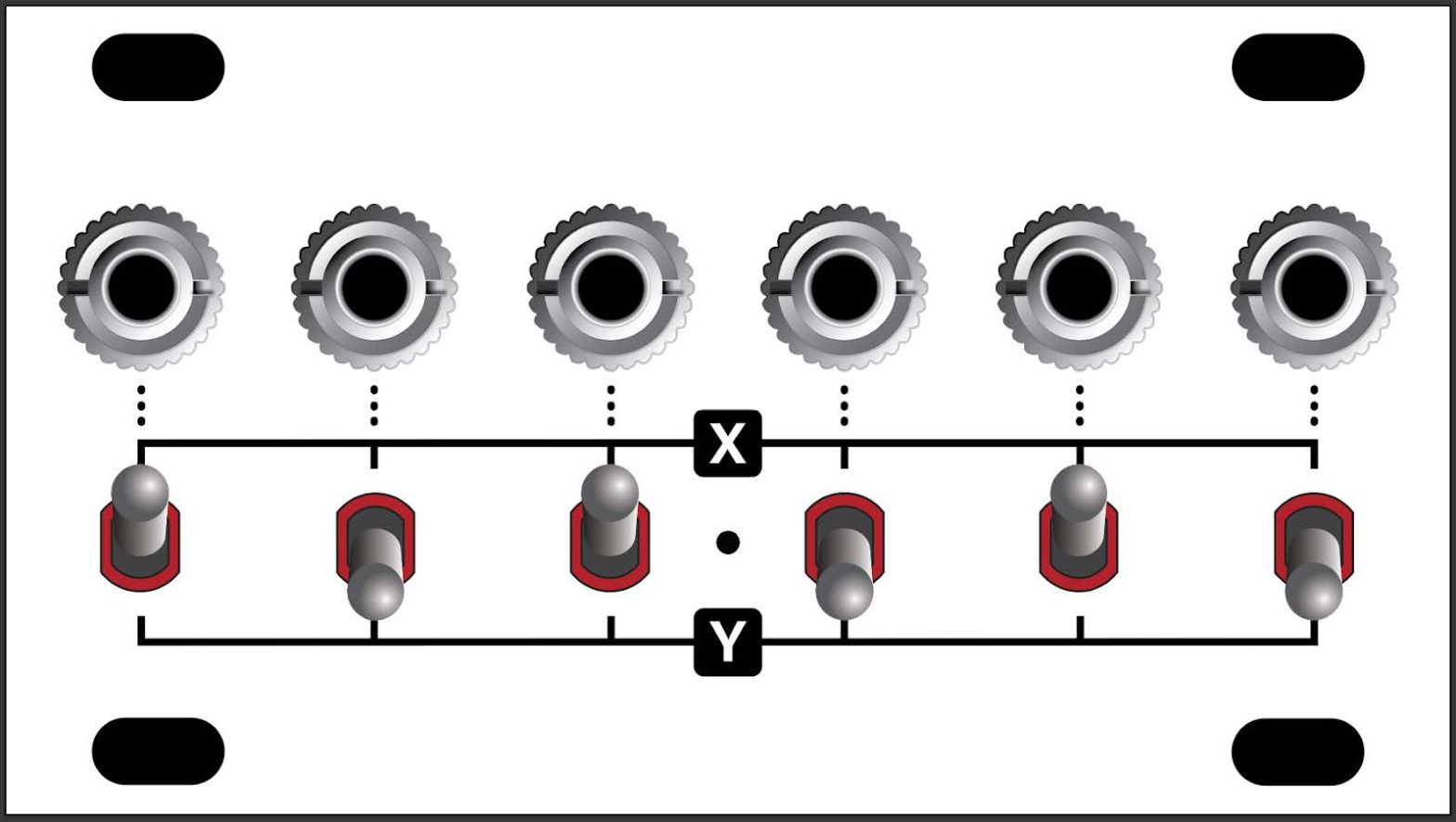
[1] Jacks : Each of these six unbuffered jacks can be assigned to either the X bus; theY bus; or switched o ff entirely, using the corresponding B us Switches [ 2].Plug an audio or CV signal into one jack, and an unbuffered version of it will appear at every other jack that has i ts B us Switch [ 2] set to the same position.[2] Bus Switches : Each j ack [ 1] has a dedicated 3-position Bus Switch:
● X Bus (top) : When a switch is in the up position, its corresponding jack accesses the X bus multiplier.● Y Bus (top) : When a switch is in the down position, its corresponding jack accesses theY bus multiplier.● OFF (middle) : When a switch i s i n the middle position, i t i s disabled and not connected to either bus.

In this illustration, we see that jacks 1 , 3 , and 5 are switched to the X bus, and jacks 2 , 4 , and 6 are switched to the Y bus — providing two separate mults.
In this illustration, we see that jacks 1 , 3 , and 5 are switched to the X bus, while jacks 2 and 4 are switched to the Y bus. Jack 6 is switched off (middle position), so i t carries no signal.
If you were to switch jack 6 to the X position (up), it will carry a mult of the X input (jack 1 ) ; if you were to switch jack 6 to the Y position (down), it will carry a mult of the Y input (jack 2 ) .
BACK PANEL
There are two 3-pin Link connectors on the rear panel, and each Switched Mult 1U module ships with one 3-pin Link cable, which you use to connect other 3-pin Link modules. Common pairings include:
- XY I/O 1U : Connect the middle (JP2) 3-pin Link connector on the back of the X Y I/O 1U to either of the 3-pin Link connectors on the back of the Switched Mult 1U. Now, any signal patched i nto the X jack on the X Y I/O 1U is multed to any Switched Mult 1U jacks that have their Bus Switches set to the X (up) position. Similarly, any signal patched into the Y jack on the XY I/O 1U is multed to any Switched Mult 1U jacks that have their Bus Switches set to the Y (down) position.
- Additional Switched Mult 1U modules : Connect either of the 3-pin Link connectors on the back of Switched Mult #1 to either of the 3-pin Link connectors on the back of Switched Mult #2. Now the X bus is shared across both Switched Mults, as is the Y bus. You can chain more modules together in the same way, which can also be useful for spreading mult jacks across the width of your modular case.
TECHNICAL SPECIFICATIONS
References
[xyz-ips snippet=”download-snippet”]