![]()
Stereo Line In 1U SystemStereo Balanced Line Audio Input
User ManualRevision: 2021.08.15
COMPLIANCE
 This device complies with Part 15 of the FCC Rules. Operation is subject to the following two conditions: (1) this device may not cause harmful interference, and (2) this device must accept any interference received, including interference that may cause undesired operation.Changes or modifications not expressly approved by Intellijel Designs, Inc. could void the user’s authority to operate the equipment. Any digital equipment has been tested and found to comply with the limits for a Class A digital device, pursuant to part 15 of the FCC Rules. These limits are designed to provide reasonable protection against harmful interference when the equipment is operated in a commercial environment. This equipment generates, uses, and can radiate radio frequency energy and, if not installed and used in accordance with the instruction manual, may cause harmful interference to radio communications.
 This device meets the requirements of the following standards and directives:EMC: 2014/30/EUEN55032:2015 ; EN55103-2:2009 (EN55024) ; EN61000-3-2 ; EN61000-3-3Low Voltage: 2014/35/EUEN 60065:2002+A1:2006+A11:2008+A2:2010+A12:2011 RoHS2: 2011/65/EU WEEE: 2012/19/EU
SYSTEM OVERVIEW
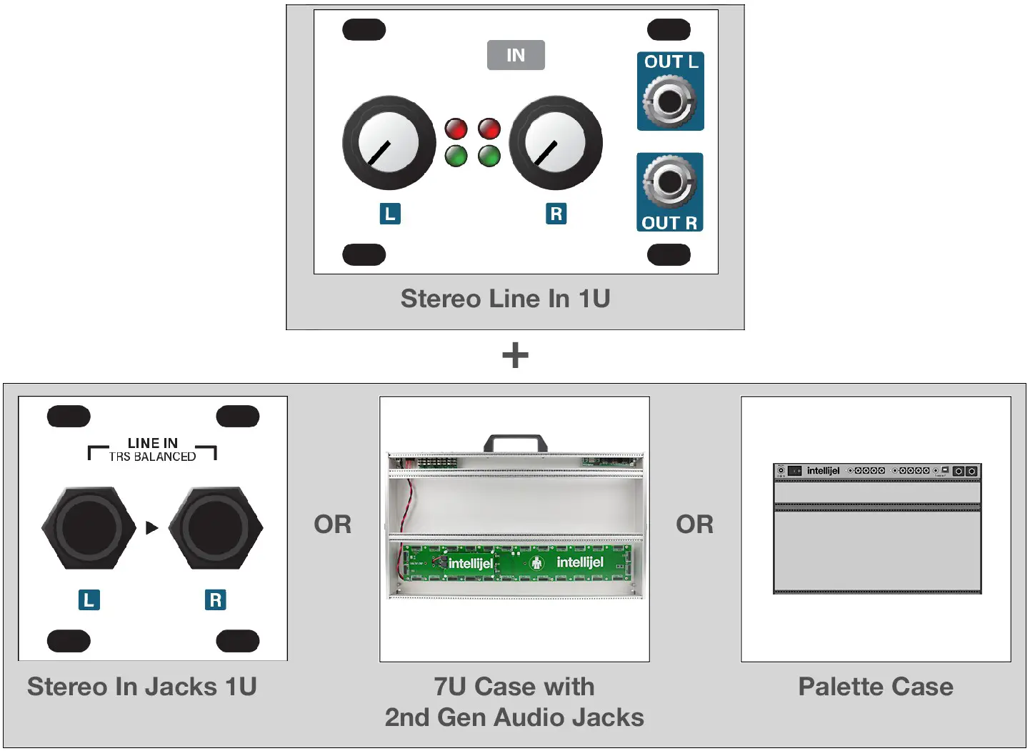
Use the Stereo Line In 1U system to bring external audio into your modular system for processing. The system works with balanced +4 dBu professional audio products and with -10dbV unbalanced gear.The Stereo Line In 1U system comprises two components:
[1] The Stereo Line In 1U module:
|
A ribbon cable connects this module to either the Stereo In Jacks 1U module, or to a compatible Intellijel case with built-in ¼” jacks. It has independent gain controls for the left and right channels, along with signal level LEDs. It contains all the gain control circuitry to drive a eurorack system at the proper levels, and features two ” output jacks for patching your external signal into other eurorack modules. |
[2] Either a Stereo In Jacks 1U module, or a case with built-in ¼” audio jacks, such as Intellijel’s Palette or 7U cases (with a 2nd generation Audio Jacks board):
|
Stereo In Jacks 1U ModuleIf you don’t own an Intellijel case with built-in compatible ¼” jacks, then you need to purchase a Stereo In Jacks 1U module, which connects via ribbon cable to the Stereo Line In 1U module to provide the ¼” TRS input jacks necessary for connecting external audio sources. |
 |
Palette CaseIf you own an Intellijel Palette case, you can connect the Stereo Line In 1U module directly to one of its built-in pairs of ¼” jacks, rather than purchasing a Stereo In Jacks 1U. |
 |
7U Case w/ 2nd Generation Audio Jacks BoardIf you own an Intellijel 7U case with a 2nd generation Audio Jacks Board (distinguished by the row of shrouded headers along its bottom edge), you can use its jacks rather than purchasing a Stereo In Jacks 1U module. If your 7U case has a 1st generation Audio Jacks Board, you can purchase a 2nd generation board to replace your old board. |
INSTALLATION
This module is designed for use within an Intellijel-standard 1U row, such as contained within the Intellijel 4U and 7U Eurorack cases. Intellijel’s 1U specification is derived from the Eurorack mechanical specification set by Doepfer that is designed to support the use of lipped rails within industry-standard rack heights.
Before You Start
Intellijel Eurorack modules are designed to be used with a Eurorack-compatible case and power supply. We recommend you use Intellijel cases and power supplies.Before installing a new module in your case, you must ensure your power supply has a free power header and sufficient available capacity to power the module:
- Sum up the specified +12V current draw for all modules, including the new one. Do the same for the -12 V and +5V current draw. The current draw will be specified in the manufacturer’s technical specifications for each module.
- Compare each of the sums to specifications for your case’s power supply.
- Only proceed with installation if none of the values exceeds the power supply’s specifications. Otherwise you must remove modules to free up capacity or upgrade your power supply.
You will also need to ensure your case has enough free space (hp) to fit the new module. To prevent screws or other debris from falling into the case and shorting any electrical contacts, do not leave gaps between adjacent modules, and cover all unused areas with blank panels. Similarly, do not use open frames or any other enclosure that exposes the backside of any module or the power distribution board.You can use a tool like ModularGrid to assist in your planning. Failure to adequately power your modules may result in damage to your modules or power supply. If you are unsure, please contact us before proceeding.
Installing Your Module
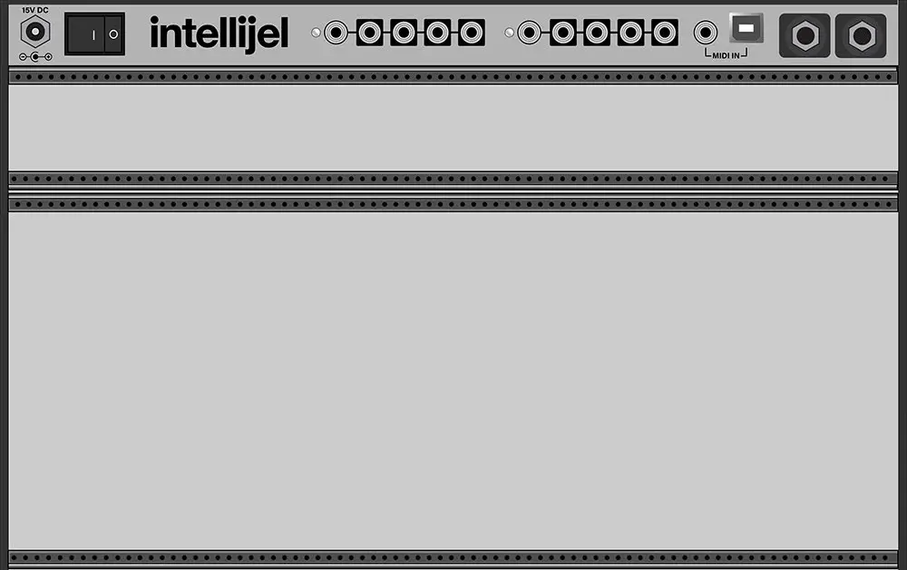
When installing or removing a module from your case always turn off the power to the case and disconnect the power cable. Failure to do so may result in serious injury or equipment damage.Ensure the 10-pin connector on the power cable is connected correctly to the module before proceeding. The red stripe on the cable must line up with the -12V pins on the module’s power connector. Different modules use different ways to indicate the -12V pins. Some may be labelled with “-12V;” a white stripe next to the -12V pins; the words “red stripe;” or some combination of these. Additionally, some modules may have shrouded headers, thus preventing backward connections.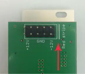 Most modules will come with the cable already connected but it is good to double check the orientation. Be aware that some modules may have headers that serve other purposes so ensure the power cable is connected to the right one.The other end of the cable, with a 16-pin connector, connects to the power bus board of your Eurorack case. Ensure the red stripe on the cable lines up with the -12V pins on the bus board. On Intellijel power supplies the pins are labelled with the label “-12V” and a thick white stripe:If you are using another manufacturer’s power supply, check their documentation for instructions.
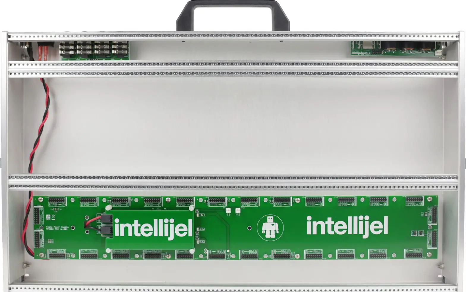
Once connected, the cabling between the module and power supply should resemble the picture below:Before reconnecting power and turning on your modular system, double check that the ribbon cable is fully seated on both ends and that all the pins are correctly aligned. If the pins are misaligned in any direction or the ribbon is backwards you can cause damage to your module, power supply, or other modules.After you have confirmed all the connections, you can reconnect the power cable and turn on your modular system. You should immediately check that all your modules have powered on and are functioning correctly. If you notice any anomalies, turn your system off right away and check your cabling again for mistakes.
Connecting a Stereo Line In 1U to a Stereo In Jacks 1U
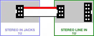
The Stereo Line In 1U module ships with a ribbon cable for connecting to a pair of ¼” TRS audio jacks — either those built-in to the 2nd generation Audio Jacks Board installed in Intellijel 7U cases; an Intellijel Palette case, or those contained within the separately available Stereo In Jacks 1U module. To connect the Stereo Line In 1U module to the Stereo In Jacks 1U module:
- Connect one end of the supplied ribbon cable to the keyed 6-pin connector on the Stereo LineIn 1U module and the other end to the keyed 6-pin connector on the Stereo In Jacks 1U.
 The signal arriving at the Stereo In Jacks’ ¼” TRS jacks is transferred into the Stereo Line In 1U module for patching into your eurorack system at the correct voltage levels.
Connecting a Stereo Line In 1U to the ¼” Jacks on a 7U Case
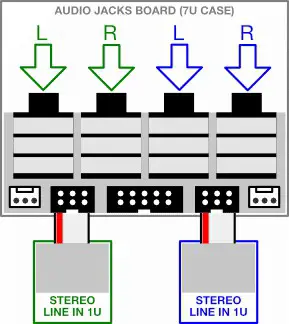
The Stereo Line In 1U module ships with a ribbon cable for connecting to a pair of ¼” TRS audio jacks — either those built-in to the 2nd generation Audio Jacks Board installed in Intellijel 7U cases; an Intellijel Palette case, or those contained within the separately available Stereo In Jacks 1U module To connect the Stereo Line In 1U module to the jacks installed in your 7U case:
- Determine whether your case uses a 1st or 2nd generation Audio Jacks Board.1st generation boards (included with cases built before early 2019) have a single connector along the bottom. 2nd generation boards have a large shrouded header flanked by two smaller shrouded headers, flanked by two link connectors.IMPORTANT: You can only connect the Stereo Line In 1U module to 7U cases with 2nd generation Audio Jacks Boards. If you have a 1st generation board, you can purchase a 2nd generation board to replace your original Audio Jacks Board.
- Connect one end of the supplied ribbon cable to the keyed 6-pin connector on the Stereo Line In 1U module and the other end to one of the two keyed 6-pin connectors on the Audio Jacks Board. Audio arriving at the corresponding pair of ¼” jacks is sent through to the Stereo Line In 1U module for patching into your eurorack system at the correct voltage levels.
Connecting Two Stereo Line In 1U Modules to a 7U Case
 report this ad
You can connect a second Stereo Line In 1U module to the other 6-pin connector on the Audio Jacks board, giving you four audio inputs in a 7U case.
- Using the ribbon cable supplied with the Stereo LineIn 1U module, connect it to one of the two keyed 6-pin connectors on the 2nd generation Audio Jacks Board.
- Connect the other Stereo Line In 1U module to the remaining keyed 6-pin connector on the Audio Jacks Board. The input for each Stereo Line In 1U module appears at the corresponding set of ¼” jacks on the Audio Jacks Board.
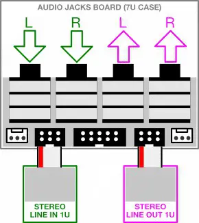
Connecting Both a Stereo Line In 1U and a Stereo Line Out 1U to a 7U Case
You can connect both a Stereo Line In 1U and a Stereo Line Out 1U module to the Audio Jacks board, giving you two inputs and two outputs on a 7U case.
- As discussed previously, connect the Stereo Line In1U module to one of the two keyed 6-pin connectors on the 2nd generation Audio Jacks Board.
- Using the ribbon cable supplied with the Stereo Line Out 1U module, connect it to the other keyed 6-pin connector on the 2nd generation Audio Jacks Board.Two of the 7U case’s ¼” inputs will then feed the Stereo Line In 1U module, and the other two will serve as outputs for the Stereo Line Out 1U module.
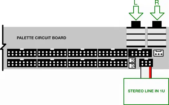
Connecting a Stereo Line In 1U to a Palette Case’s ¼” Jacks
The Stereo Line In 1U module ships with a ribbon cable for connecting to a pair of ¼” TRS audio jacks — either those built-in to the 2nd generation Audio Jacks Board installed in Intellijel 7U cases; an Intellijel Palette case, or those contained within the separately available Stereo Out Jacks 1U module.To connect the Stereo Line In 1U module to the jacks installed in your Intellijel Palette case:
- Connect one end of the supplied ribbon cable to the keyed 6-pin connector on the Stereo Line In 1U module and the other end to the single keyed 6-pin connector on the Palette case’s built-in circuit board.Audio arriving at the corresponding pair of ¼” jacks is sent through to the Stereo Line In 1U module for patching into your eurorack system at the correct voltage levels.
FRONT PANEL (Stereo Line In 1U)
Controls
[A] INPUT GAIN LScales the input signal level, which arrives via a ¼” jack (ie. a Stereo Line In 1U module, a Palette case, or a 7U case with 2nd generation Audio Jacks board) connected to the rear of this module.Fully counterclockwise, the input is completely attenuated. Set fully clockwise, +15dB of gain is applied to the input signal before sending it to the OUT L [1] jack.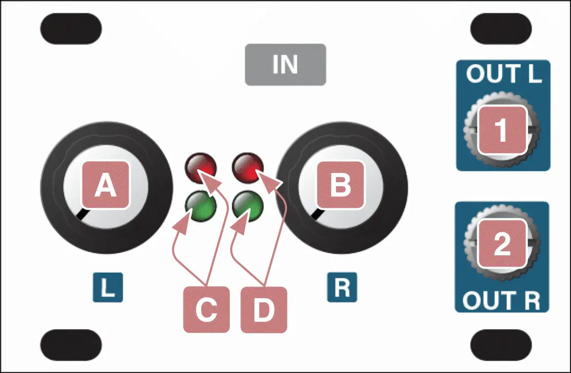 [B] INPUT GAIN RSame as INPUT GAIN L [A], except it works on the ¼” jack connected to the module’s right channel, and outputs the attenuated/amplified signal to the OUT R [2] jack.
[C] LEVEL L LEDsThis two-LED ladder indicates the amount of signal being fed to the OUT L [1] jack via the left channel’s connected ¼” jack and attenuated/amplified by the INPUT GAIN L [A] knob).The green LED lights at the presence of signal, and grows brighter as the signal level increases. The red LED lights turns on when the OUT L level is around 9V.
[D] LEVEL R LEDsThis two-LED ladder indicates the amount of signal being fed to the OUT R [s] jack via the right channel’s connected ¼” jack and attenuated/amplified by the INPUT GAIN R [A] knob).The green LED lights at the presence of signal, and grows brighter as the signal level increases. The red LED lights turns on when the OUT R level is around 9V.
Inputs & Outputs
[1] L OutputThis jack carries the amplified, eurorack-level signal of an external signal patched into the connected device’s left ¼” input jack (i.e, a Stereo In Jacks 1U module; a Palette case; or an Intellijel 7U case with a 2nd generation Audio Jacks Board).The level of this signal is governed by the INPUT GAIN L knob [A], and can be monitored using the corresponding LEVEL L LEDs [C].[2] R OutputThis jack carries the amplified, eurorack-level signal of an external signal patched into the connected device’s right ¼” input jack (i.e, a Stereo In Jacks 1U module; a Palette case; or an Intellijel 7U case with a 2nd generation Audio Jacks Board).The level of this signal is governed by the INPUT GAIN R knob [B], and can be monitored using the corresponding LEVEL R LEDs [D].
FRONT PANEL (Stereo In Jacks 1U)
Inputs & Outputs
[1] LINE IN (L)An external signal patched into this ¼” TRS jack is passed through to the left channel of a connected Stereo Line In 1U module, where it’s amplified to eurorack levels and made available to other eurorack modules via the left ” output on the Stereo Line In 1U module.This input supports both professional, balanced +4 dBu equipment and prosumer, unbalanced -10 dbV level gear.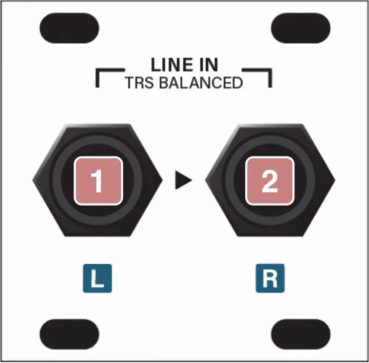
[2] LINE IN (R)An external signal patched into this ¼” TRS jack is passed through to the right channel of a connected Stereo Line In 1U module, where it’s amplified to eurorack levels and made available to other eurorack modules via the right ” output on the Stereo Line In 1U module.This input supports both professional, balanced +4 dBu equipment and prosumer, unbalanced -10 dbV level gear.
TECHNICAL SPECIFICATIONS
Stereo Line In 1U
| Width | 12 hp |
| Maximum Depth | 38 mm |
| Current Draw | 18 mA @ +12V 112 mA @ -12V |
| Maximum Balanced Input Line Level | +13dbU |
| Maximum Gain | 15db |
Stereo In Jacks 1U
| Width | 8 hp |
| Maximum Depth | 39 mm |
| Current Draw | 0 mA (passive module) |
References
[xyz-ips snippet=”download-snippet”]