VCO 1USyncable, Multi-Waveform Analog Oscillator & LFO
COMPLIANCE
 This device complies with Part 15 of the FCC Rules. Operation is subject to the following two conditions: (1) this device may not cause harmful interference, and (2) this device must accept any interference received, including interference that may cause undesired operation.Changes or modifications not expressly approved by Intellijel Designs, Inc. could void the user’s authority to operate the equipment.Any digital equipment has been tested and found to comply with the limits for a Class A digital device, pursuant to part 15 of the FCC Rules. These limits are designed to provide reasonable protection against harmful interference when the equipment is operated in a commercial environment. This equipment generates, uses, and can radiate radio frequency energy and, if not installed and used inaccordance with the instruction manual may cause harmful interference to radio communications.
This device meets the requirements of the following standards and directives:EMC: 2014/30/EUEN55032:2015 ; EN55103-2:2009 (EN55024) ; EN61000-3-2 ; EN61000-3-3Low Voltage: 2014/35/EUEN 60065:2002+A1:2006+A11:2008+A2:2010+A12:2011RoHS2: 2011/65/EUWEEE: 2012/19/EU
INSTALLATION
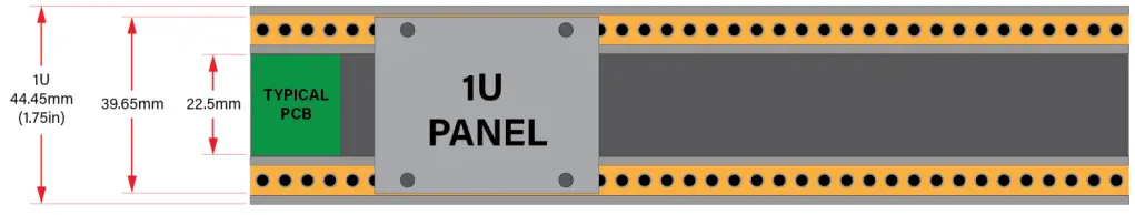
This module is designed for use within an Intellijel-standard 1U row, such as contained within the Intellijel 4U, 7U, and Palette Eurorack cases. Intellijel’s 1U specification is derived from the Eurorack mechanical specification set y Doepfer that is designed to support the use of lipped rails within industry-standard rack heights.
Before You Start
Intellijel Eurorack modules are designed to be used with a Eurorack-compatible case and power supply. We recommend you use Intellijel cases and power supplies.Before installing a new module in your case, you must ensure your power supply has a free power header and sufficient available capacity to power the module:
- Sum up the specified +12V current draw for all modules, including the new one. Do the same for the -12 V and +5V current draw. The current draw will be specified in the manufacturer’s technical specifications for each module.
- Compare each of the sums to specifications for your case’s power supply.
- Only proceed with the installation if none of the values exceeds the power supply’s specifications.Otherwise, you must remove modules to free up capacity or upgrade your power supply.You will also need to ensure your case has enough free space (hp) to fit the new module. To prevent screws or other debris from falling into the case and shorting any electrical contacts, do not leave gaps between adjacent modules, and cover all unused areas with blank panels. Similarly, do not use open frames or any other enclosure that exposes the backside of any module or the power distribution board.
You can use a tool like ModularGrid to assist in your planning. Failure to adequately power your modules may result in damage to your modules or power supply. If you are unsure, please contact us before proceeding.
Installing Your Module
When installing or removing a module from your case always turn off the power to the case and disconnect the power cable. Failure to do so may result in serious injury or equipment damage.Ensure the 10-pin connector on the power cable is connected correctly to the module before proceeding.The red stripe on the cable must line up with the -12V pins on the module’s power connector. The pins are indicated with the label -12V, a white stripe next to the connector, the words “red stripe”, or some combination of those indicators. On Intellijel power supplies the pins are labeled with the label “-12V” and a thick white stripe.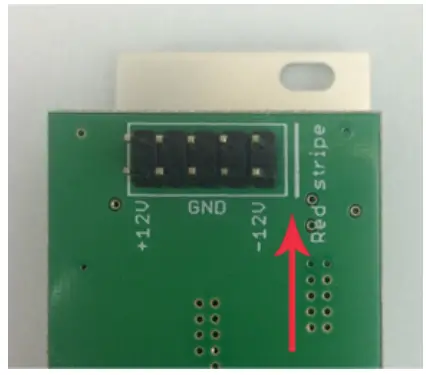 Sometimes the connectors are shrouded, ensuring the cable can only be oriented in one direction.Most modules will come with the cable already connected but it is good to double-check the orientation. Be aware that some modules may have headers that serve other purposes so ensure the cable is connected to the right one.
The other end of the cable, with a 16-pin connector, connects to the power bus board of your Eurorack case. Ensure the red stripe on the cable lines up with the -12V pins on the bus board. On Intellijel power supplies the pins are labeled with the label “-12V” and a thick white stripe. Sometimes the connectors are shrouded, ensuring the cable can only be oriented in one direction.If you are using another manufacturer’s power supply, check their documentation for instructions.
Once connected, the cabling between the module and power supply should resemble the picture below:
Before reconnecting power and turning on your modular system, double-check that the ribbon cable is fully seated on both ends and that all the pins are correctly aligned. If the pins are misaligned in any direction or the ribbon is backward you can cause damage to your module, power supply, or other modules.After you have confirmed all the connections, you can reconnect the power cable and turn on your modular system. You should immediately check that all your modules have powered on and are functioning correctly. If you notice any anomalies, turn your system off right away and check your cabling again for mistakes.
 FRONT PANEL
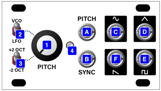
- PITCH knob: Adjusts either the pitch of the VCO or the rate of the LFO — depending on the position of the VCO/LFO [2]switch. Specifically:VCO: The PITCH knob controls pitch over a 3-octave range, which can be extended to 7-octaves using the OCTAVE [3] switch.LFO: The PITCH knob controls the LFO rate over a larger (approx 7-octave range), which can be extended to over 11-octaves using the OCTAVE [3] switch.
- VCO/LFO switch: Sets whether the oscillator runs at audio (VCO) or low frequency (LFO) rates.With nothing patched into the PITCH [A] input, the VCO and LFO ranges are as follows:VCO range:● Minimum pitch = 16 Hz(when OCTAVE [3] = ‘ -2 OCT ’ and PITCH [1] knob is fully counterclockwise)● Maximum pitch = 2.048 kHz(when OCTAVE [3] = ‘ +2 OCT ’ and PITCH [1] knob is fully clockwise)LFO range:● Minimum LFO rate = 23 seconds(when OCTAVE [3] = ‘ -2 OCT ’ and PITCH [1] knob is fully counterclockwise)● Maximum LFO rate = 52 Hz(when OCTAVE [3] = ‘ +2 OCT ’ and PITCH [1] knob is fully clockwise)Patching a voltage into the PITCH [A] input extends these ranges further.NOTE: These are the frequency ranges as set at the factory. If you’re comfortable with your tweaking skills and would prefer a slower LFO rate (at the expense of maximum pitch), or a higher maximum pitch (at the cost of increasing the minimum LFO rate), you can use the back panel’s OFFSET trimmer to do this — but you’ll want to keep your trim tool away from the SCALE trimmer. Proceed at your own risk.
- OCTAVE switch: This three-position switch raises (in the top position) or lowers (in the bottom position) the oscillator’s pitch (or LFO rate) by two octaves.
- OUTPUT VOLTAGE LED: Displays the TRIANGLE [D] wave’s output voltage. Positive voltages are indicated by a green LED, and negative voltages by a red LED. The intensity of the LED represents the relative voltage level. This is particularly useful when using the module in LFO mode since it gives a visual indication of the LFO rate. Obviously, at VCO rates, the LED modulates too quickly for the naked eye to discern the voltage changes.[A] PITCH IN: 1V/OCT pitch input for controlling the pitch of the oscillator with a sequencer or voltage source.[B] SYNC IN: The periodicity of a waveform patched into SYNC IN will force the VCO to cycle at some whole number multiplier of the input signal.Different timbres are produced when the VCO’s oscillator runs at a different pitch than the one patched into SYNC IN. That’s because, in order to synchronize to the SYNC IN waveform, the VCO must restart its wave cycle every time the input waveform crosses zero in the positive direction (“hard” sync). This causes abrupt changes to the oscillator’s waveform, which results in a harmonically rich sound. Further harmonic complexity is achieved by modulating the pitch of the VCO, which causes its harmonic structure to constantly change as each cycle resets at a different location. This alters the VCO’s harmonic complexity over time while its pitch continues to be governed by that of the SYNC IN signal.[C] SINE OUT: Sine wave output. The pure waveform that outputs only the fundamental frequency with no harmonics. Good for adding the bottom end to a sound, since no higher harmonics come into play. Used as an LFO, it allows for smooth transitions between peaks, though hovers around those peaks for a longer period of time than the linear Triangle wave.[D] TRIANGLE OUT: Triangle wave output. This waveform has a lot of energy in its fundamental frequency and a bit of additional energy in its first few odd harmonics. This makes a Triangle wave still sound relatively pure (like a sine wave), only brighter — but not nearly as bright as a square wave (which also has odd harmonics). Triangle waves are excellent for LFO use, since they ramp smoothly and linearly between maximum and minimum values.[E] SQUARE OUT: Square wave output. Like triangle waves, square waves have only odd harmonics. But unlike triangle waves, the energy in the higher harmonics does not dissipate as quickly, meaning they have more (and louder) upper harmonics, and therefore sound much brighter than Triangle waves. Square waves are also good for LFOs, since they switch back and forth between two discrete levels, without ramping between them.[F] SAWTOOTH OUT: Sawtooth wave output. This waveform has both even and odd harmonics, which makes this the brightest and buzziest sounding output. Sawtooth waves are ideal for use in subtractive synthesis, where they’re run through a filter that removes (and helps shape) the harmonic content.
TECHNICAL SPECIFICATIONS
| Width | 14 hp |
| Maximum Depth | 37.5 mm |
| Current Draw | 19 mA @ +12V16 mA @ -12V |
VCO 1U Manual
References
[xyz-ips snippet=”download-snippet”]