intellijel Zeroscope 1U User Manual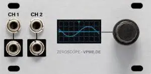
COMPLIANCE
![]() This device complies with Part 15 of the FCC Rules. Operation is subject to the following two conditions: (1) this device may not cause harmful interference, and (2) this device must accept any interference received, including interference that may cause undesired operation.Changes or modifications not expressly approved by Intellijel Designs, Inc. could void the user’s authority to operate the equipment.Any digital equipment has been tested and found to comply with the limits for a Class A digital device, pursuant to part 15 of the FCC Rules. These limits are designed to provide reasonable protection against harmful interference when the equipment is operated in a commercial environment. This equipment generates, uses, and can radiate radio frequency energy and, if not installed and used in accordance with the instruction manual, may cause harmful interference to radio communications.
This device complies with Part 15 of the FCC Rules. Operation is subject to the following two conditions: (1) this device may not cause harmful interference, and (2) this device must accept any interference received, including interference that may cause undesired operation.Changes or modifications not expressly approved by Intellijel Designs, Inc. could void the user’s authority to operate the equipment.Any digital equipment has been tested and found to comply with the limits for a Class A digital device, pursuant to part 15 of the FCC Rules. These limits are designed to provide reasonable protection against harmful interference when the equipment is operated in a commercial environment. This equipment generates, uses, and can radiate radio frequency energy and, if not installed and used in accordance with the instruction manual, may cause harmful interference to radio communications.
![]() This device meets the requirements of the following standards and directives:EMC: 2014/30/EU EN55032:2015 ; EN55103-2:2009 (EN55024) ; EN61000-3-2 EN61000-3-3Low Voltage: 2014/35/EU EN 60065:2002+A1:2006+A11:2008+A2:2010+A12:2011RoHS2: 2011/65/EUWEEE: 2012/19/EU
This device meets the requirements of the following standards and directives:EMC: 2014/30/EU EN55032:2015 ; EN55103-2:2009 (EN55024) ; EN61000-3-2 EN61000-3-3Low Voltage: 2014/35/EU EN 60065:2002+A1:2006+A11:2008+A2:2010+A12:2011RoHS2: 2011/65/EUWEEE: 2012/19/EU
INSTALLATION
This module is designed for use within an Intellijel-standard 1U row, such as contained within the Intellijel 4U and 7U Eurorack cases. Intellijel’s 1U specification is derived from the Eurorack mechanical specification set by Doepfer that is designed to support the use of lipped rails within industry standard rack heights.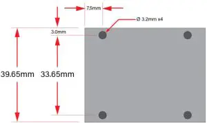

Before Your Start
Intellijel Eurorack modules are designed to be used with a Eurorack-compatible case and power supply. We recommend you use Intellijel cases and power supplies.Before installing a new module in your case, you must ensure your power supply has a free power header and sufficient available capacity to power the module:
- Sum up the specified +12V current draw for all modules, including the new one. Do the same for the -12 V and +5V current draw. The current draw will be specified in the manufacturer’s technical specifications for each module.
- Compare each of the sums to specifications for your case’s power supply.
- Only proceed with installation if none of the values exceeds the power supply’s specifications. Otherwise you must remove modules to free up capacity or upgrade your power supply.
You will also need to ensure your case has enough free space (hp) to fit the new module. To prevent screws or other debris from falling into the case and shorting any electrical contacts, do not leave gaps between adjacent modules, and cover all unused areas with blank panels. Similarly, do not use open frames or any other enclosure that exposes the backside of any module or the power distribution board.
You can use a tool like ModularGrid to assist in your planning. Failure to adequately power your modules may result in damage to your modules or power supply. If you are unsure, please contact us before proceeding.
Installing Your Module
When installing or removing a module from your case always turn off the power to the case and disconnect the power cable. Failure to do so may result in serious injury or equipment damage.Ensure the 10-pin connector on the power cable is connected correctly to the module before proceeding. The red stripe on the cable must line up with the -12V pins on the module’s power connector. The pins are indicated with the label -12V, a white stripe next to the connector, the words “red stripe”, or some combination of those indicators.Most modules will come with the cable already connected but it is good to double check the orientation. Be aware that some modules may have headers that serve other purposes so ensure the cable is connected to the right one.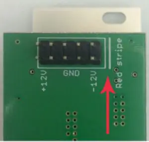 The other end of the cable, with a 16-pin connector, connects to the power bus board of your Eurorack case. Ensure the red stripe on the cable lines up with the -12V pins on the bus board. On Intellijel power supplies the pins are labelled with the label “-12V” and a thick white stripe:If you are using another manufacturer’s power supply, check their documentation for instructions.
Once connected, the cabling between the module and power supply should resemble the picture below: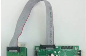
Before reconnecting power and turning on your modular system, double check that the ribbon cable is fully seated on both ends and that all the pins are correctly aligned. If the pins are misaligned in any direction or the ribbon is backwards you can cause damage to your module, power supply, or other modules.After you have confirmed all the connections, you can reconnect the power cable and turn on your modular system. You should immediately check that all your modules have powered on and are functioning correctly. If you notice any anomalies, turn your system off right away and check your cabling again for mistakes.
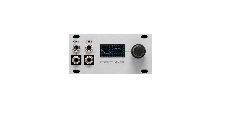
FRONT PANEL
Inputs & Outputs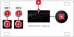
- CH 1 input: The input is DC coupled and accepts signals between -10V and +10V.
- CH 2 input: This input, like CH 1, is DC coupled and accepts signals between -10V and +10V.
- CH 1 output: The signal appearing at the CH 1 input jack is normalled to the CH 1 output jack, so signals pass unimpeded through the Zeroscope 1U. This allows you to monitor signals without needing to re-patch or use signal multipliers.
- CH 2 output: As with CH 1, the signal appearing at the CH 2 input jack is normalled to the CH 2 output jack, so signals pass unimpeded through the Zeroscope 1U.
Controls
- [A] Scope: In Scope or X-Y modes, this screen displays both the CH 1 and CH 2 waveforms, whilein Tune mode, it displays their frequency by either Hz or note name.
- [B] Encoder: This push-function encoder serves multiple functions — controlling the appearance ofthe scope, and enabling both the selection of parameters and the editing of their values.
BASIC OPERATION
In its basic mode, Zeroscope 1U displays the waveforms for both CH 1 and CH 2, and gives you control over the display height of these two waveforms plus their displayed periodicity.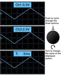
- Connect CV or audio signals to either or both the CH 1 and CH 2 inputs.Both inputs are DC coupled and accept signals between -10V and +10V. Either can serve as a trigger source, configured to detect either the rising or falling edge of the waveform (as described later in the Trigger Source discussion). All inputs are normalled to the jacks below.
- Press the encoder to cycle through the three three basic display options.Specifically, each press cycles between:
- CH 1 Display Value (volts/division)
- CH 2 Display Value (volts/division)
- T (Time) Display Value (seconds/division, both channels)
- Turn the encoder to change the option’s value. Specifically:
- CH 1: With this option displayed, turning the encoder sets CH 1’s gain (height of displayed signal) between 0.5 volts/division and 10.0 volts/division.
- CH 2: With this option displayed, turning the encoder sets CH 2’s gain (height of displayed signal) between 0.5 volts/division and 10.0 volts/division. CH 2’s gain level is completely independent from CH 1’s.
- T: With this option displayed, turning the encoder sets the waveform’s time base between 10 s/div and 10 µs/div with seventeen incremental values between these two extremes.NOTE: At a setting of 10 µs/div, only CH 1 is displayed. Also, because the Zeroscope employs a simple anti-aliasing filter, an input signal running at a frequency higher than the timebase may produce a misleading waveform.
ADVANCED OPERATION
Zeroscope 1U offers several advanced display and triggering options, located within an Advanced Settings menu.
- Long-press (>1 sec) the encoder to open the Advanced Settings menu.A small menu of options appears to the right of the display.
- Turn the encoder to select and highlight which of six Advanced Settings options you wish to edit.There are six options accessible in this menu. These are, from top-to-bottom:

- SCOPE type
- TRIGGER Source
- TRIGGER DETECTION LEVEL
- CH 1 offset
- CH 2 offset
- GRID display
- With the desired option highlighted, push-turn the encoder to edit its value.That is, turn the encoder while it’s fully depressed to change values. The following sections discuss each advanced operation in detail.

Scope Type
With this option selected, push-turn the encoder to select what you want displayed on the Zeroscope. There are three options:
ScopeStandard graphical display, with time displayed on the X-axis and voltage displayed on the Y-axis.
X-YAlternate graphical display with CH 1 driving the X-axis and CH 2 driving the Y-axis.TuneAlphanumerical tuning display, which you can configure to show either Hz values or note names (see below).
Using Tune Mode
Tune Mode displays CH 1 and CH 2 frequencies either by number of cycles-per-second (Hz) or byNote Name. Once in Tune mode, simply press the encoder to toggle between the two display options.NOTE: The input signal must be at least +2V in order for the pitch detector to work.
Hz DisplayThe top line displays the frequency (in Hz) of the signal appearing at CH 1, and the second line displays the frequency of the signal appearing at CH 2.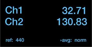
Note Name Display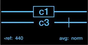 The top line shows CH 1, and the second line shows CH 2.Zeroscope displays the note name closest to the incoming pitch, plus a vertical line indicating how far the pitch is from that note (from -45 to +45 cents).A note is sharp if the vertical line is to the right of the note name. For example, in this illustration the vertical line is to the right of the note name for CH 2, indicating that CH 2 is playing a C3 (“middle C”), but that the note is sharp.A note is flat if the vertical line is to the left of the note name.A note is perfectly in tune if a box surrounds the note name. In this illustration, the box around the note name for CH 1 indicates that it’s playing a C1 note, and that it’s perfectly in tune
Reference Pitch and Averaging Time
Both the Hz Display and the Note Name Display have two additional options at the bottom of the scope: ref and avg.
refThis displays the reference pitch used by the tuner (which displays the number of Hz to which the A above middle-C is tuned). Most devices default to 440Hz, but other standards are sometimes used.
avgThis displays how long the Zeroscope spends averaging out frequency variations before it recalculates and reports a new note name. There are three options: slow; norm; and fast. Fast is very sensitive to fluctuations on input, while slow is not. Norm is in the middle
A small indicator arrow to the left of the ref or avg parameter indicates which will be changed by rotating the encoder. To change whether the encoder edits ref or avg, switch between Hz and Note Name displays. Specifically:
- After entering Tune mode, wait five seconds for the little Tune mode indicator in the upper right corner to extinguish.
- With Hz display active, turn the encoder (without pushing it) to change the avg setting (slow, normal, fast)
- Switch to the Note Name display, and turn the encoder (without pushing it) to change the ref tuning value.
Trigger SourceWith this option selected, push-turn the encoder to select how you want to trigger the Zeroscope.You have five triggering options:
Trg off The scope is untriggeredTrg![]() The scope triggers on the rising edge of the signal at CH 1Trg
The scope triggers on the rising edge of the signal at CH 1Trg ![]() The scope triggers on the falling edge of the signal at CH 1Trg
The scope triggers on the falling edge of the signal at CH 1Trg ![]() The scope triggers on the rising edge of the signal at CH 2Trg
The scope triggers on the rising edge of the signal at CH 2Trg ![]() The scope triggers on the falling edge of the signal at CH 2
The scope triggers on the falling edge of the signal at CH 2
Trigger Detection LevelWith this option selected, push-turn the encoder to set the level at which trigger detection occurs. Trigger threshold can be offset ± 10V (-10000µV – +10000µV). At 0V (the default), a typical bipolar waveform triggers when it crosses the 0-line. Trigger levels are graphically indicated on theZeroscope display.If you set a trigger threshold beyond the voltage limits of the current waveform, you’ll see a small T? icon appear in the lower left corner of the display, indicating that it failed to detect a trigger.
CH 1 Offset
With this option selected, push-turn the encoder to set a display offset for the CH 1 waveform. Waveforms can be offset ± 10V (-10000µV – +10000µV).Offsetting waveforms is particularly useful if you want to display CH 1’s waveform above (or below) CH 2’s waveform. For example, assume CH 1 and CH 2 are both typical ± 5V waveforms. If you set both the CH 1 and CH 2 Display Values to 5.0 V per division, then each waveform is ½ the entire height of the scope. If you set the CH 1 Offset to +5000 (+5V) and the CH 2 Offset (described below) to -5000 (-5V), then CH 1’s waveform is displayed in the top half of the scope, and CH 2’s is displayed in the bottom half.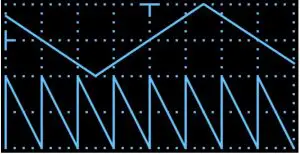
CH 2 OffsetWith this option selected, push-turn the encoder to set a display offset for the CH 2 waveform. Waveforms can be offset ± 10V (-10000µV – +10000µV).Grid DisplayWith this option selected, push-turn the encoder to select between two options:grd: on turns on the scope’s background gridgrd: — turns off the scope’s background grid
Screen Saver
In order to extend the life of your screen, Zeroscope 1U features a built-in screen saver, which turnsoff the display after a user-definable length of time. If the screen has turned off, simply press or turnthe encoder to turn the display back on.To set the amount of time until the screen saver dims the screen:
- Long-press (>1 sec) the encoder to open the Advanced Settings menu.A small menu of options appears to the right of the display.
- Turn the encoder to select the SCOPE option.
- With the SCOPE option highlighted, push-turn the encoder and select TUNE mode.
- Turn the encoder to select the SCREEN SAVER option.
- Push-turn the encoder to set how long Zeroscope should wait until it turns off the display screen.You can choose between: 1 min, 2 min, 5 min, 10 min, 30 min, 1 hour, 2 hour, and never.
FIRMWARE
Firmware updates, if available, are contained within the latest Intellijel Firmware Updater application, which you can download from the product’s page on the Intellijel.com website. The application is available in both Macintosh and Windows formats, and will install firmware into your module over USB. Download the app, then use the drop down list at the top of the application to select the product you wish to update, and the firmware version you want to install. Click the Instructions button to read specific instructions for updating your module.
Change Log
 report this ad
1.4 (Oct 26, 2020)
- FEATURE: Added an option to set the amount of time until the screen saver darkens the screen. Time is accessed via a menu on the TUNER screen, as described in Screen Saver. 1.3 (Nov 14, 2019)
- FEATURE: Added a Screen Saver1.2 (Jan 08, 2019)
- Initial product release
TECHNICAL SPECIFICATIONS
|
Width |
16 hp |
|
Maximum Depth |
26 mm |
| Current Draw |
8 mA @ +12V 0 mA @ -12V |
References
[xyz-ips snippet=”download-snippet”]