

Conforms to ANSI STD Z83.11b-2009(R2012) Certified to CSA STD 1.8b-2009(R2012)
CHAR BROILER
Installation and Operation InstructionsModels: T-CBR15, T-CBR24, T-CBR36, T-CBR48, T-CBL15, T-CBL24, T-CBL36, T-CBL48

IMPORTANT FOR FUTURE REFERENCE
Please complete this information and retain this manual for the life of the equipment. For Warranty Service and/or parts, this information is required.
Model NumberSerial NumberDate Purchased
![]() WARNING: For your safety, do not store or use gasoline or other flammable vapors or liquids in the vicinity of this or any other appliances. Keep the area free and clear of combustible. (See ANSI Z83. 14B, 1991).
WARNING: For your safety, do not store or use gasoline or other flammable vapors or liquids in the vicinity of this or any other appliances. Keep the area free and clear of combustible. (See ANSI Z83. 14B, 1991).![]() WARNING: Improper installation, adjustment, alteration, service, or maintenance can cause property damage, injury, or death. Read the installation operating and maintenance instructions thoroughly before installing or servicing this equipment.
WARNING: Improper installation, adjustment, alteration, service, or maintenance can cause property damage, injury, or death. Read the installation operating and maintenance instructions thoroughly before installing or servicing this equipment.![]() WARNING: Instructions must be posted in a prominent location. All safety precautions must be taken in the event the user smells gas. Safety information can be obtained from your local gas supplier.
WARNING: Instructions must be posted in a prominent location. All safety precautions must be taken in the event the user smells gas. Safety information can be obtained from your local gas supplier.![]() CAUTION: These models are designed, built, and sold for commercial use only. If these models are positioned so the general public can use the equipment, make sure that cautions, warnings, and operating instructions are clearly posted near each unit so that anyone using the equipment will use it correctly and not injure themselves or damage the equipment.
CAUTION: These models are designed, built, and sold for commercial use only. If these models are positioned so the general public can use the equipment, make sure that cautions, warnings, and operating instructions are clearly posted near each unit so that anyone using the equipment will use it correctly and not injure themselves or damage the equipment.
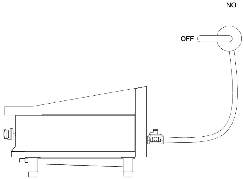
GAS PRESSURE The appliance and its individual shutoff valve (to be supplied by the user) must be disconnected from the gas supply piping system during any pressure testing of that system at test pressures in excess of ½ psi (3.45 kPa). The appliance must be isolated from the gas supply piping system by closing its individual manual shutoff valve during any pressure testing of the gas supply piping system at test pressures equal to or less than ½ psi (3.45 kPa).![]() WARNING: A factory-authorized agent should handle all maintenance and repairs. Before doing any maintenance or repairs, contact your authorized service representative.Congratulations on your purchase of Eurodib commercial cooking equipment. Eurodib takes pride in the design and quality of our products. When used as intended and with proper care and maintenance, you will experience years of reliable operation from this equipment. To ensure best results, it is important that you read and follow the instructions in this manual carefully.LOCATION OF DATA PLATEThe data plate is located on the side panel.IMMEDIATELY INSPECT FOR SHIPPING DAMAGEAll containers should be examined for damage before and during unloading. The freight carrier has assumed responsibility for its safe transit and delivery. If equipment is received damaged, either apparent or concealed, a claim must be made with the delivering carrier.A. Apparent damage or loss must be noted on the freight bill at the time of delivery. It must then be signed by the carrier representative (Driver). If this is not done, the carrier may refuse the claim. The carrier can supply the necessary forms.B. Concealed damage or loss if not apparent until after the equipment is uncrated, a request for inspection must be made to the carrier within 15 days. The carrier should arrange an inspection. Be certain to hold all contents and packaging material.A qualified installer who thoroughly read understands and follows these instructions should perform installation and maintenance.If you have questions concerning the installation, operation, maintenance, or service of this product, write to Eurodib.
WARNING: A factory-authorized agent should handle all maintenance and repairs. Before doing any maintenance or repairs, contact your authorized service representative.Congratulations on your purchase of Eurodib commercial cooking equipment. Eurodib takes pride in the design and quality of our products. When used as intended and with proper care and maintenance, you will experience years of reliable operation from this equipment. To ensure best results, it is important that you read and follow the instructions in this manual carefully.LOCATION OF DATA PLATEThe data plate is located on the side panel.IMMEDIATELY INSPECT FOR SHIPPING DAMAGEAll containers should be examined for damage before and during unloading. The freight carrier has assumed responsibility for its safe transit and delivery. If equipment is received damaged, either apparent or concealed, a claim must be made with the delivering carrier.A. Apparent damage or loss must be noted on the freight bill at the time of delivery. It must then be signed by the carrier representative (Driver). If this is not done, the carrier may refuse the claim. The carrier can supply the necessary forms.B. Concealed damage or loss if not apparent until after the equipment is uncrated, a request for inspection must be made to the carrier within 15 days. The carrier should arrange an inspection. Be certain to hold all contents and packaging material.A qualified installer who thoroughly read understands and follows these instructions should perform installation and maintenance.If you have questions concerning the installation, operation, maintenance, or service of this product, write to Eurodib.
SAFETY PRECAUTIONS
![]() DANGER: This symbol warns of imminent hazards, which could result in serious injury or death.
DANGER: This symbol warns of imminent hazards, which could result in serious injury or death.![]() WARNING: This symbol refers to a potential hazard or unsafe practice, which could result in serious injury or death.
WARNING: This symbol refers to a potential hazard or unsafe practice, which could result in serious injury or death.![]() CAUTION: This symbol refers to a potential hazard or unsafe practice, which could result in minor or moderate injury or product or property damage.
CAUTION: This symbol refers to a potential hazard or unsafe practice, which could result in minor or moderate injury or product or property damage. ![]() NOTICE: This symbol refers to information that needs special attention or must be fully understood even though not dangerous.
NOTICE: This symbol refers to information that needs special attention or must be fully understood even though not dangerous.![]() NOTICE: This product is intended for commercial use only. Not for household use.
NOTICE: This product is intended for commercial use only. Not for household use.![]() NOTICE: Local codes regarding installation vary greatly from one area to another. The National Fire Protection Association, Inc., states in its NFPA96 latest edition that local codes are “Authority Having Jurisdiction” when it comes to requirements for the installation of equipment. Therefore, the installation should comply with all local codes.
NOTICE: Local codes regarding installation vary greatly from one area to another. The National Fire Protection Association, Inc., states in its NFPA96 latest edition that local codes are “Authority Having Jurisdiction” when it comes to requirements for the installation of equipment. Therefore, the installation should comply with all local codes.
GENERAL INSTALLATION INSTRUCTIONS
Ensure that the gas supply and gas type, as shown on the unit nameplate, agree.Unit installation must conform with the National Fuel Gas Code, ANSI Z223.1/NFPA 54, the National Gas Installation Code, CSA-B149.1, or the Propane Installation Code, CSA-B149.2 as applicable and in accordance with local codes.Screw the legs into the permanently fastened nuts on the four corners of the unit and tighten them by hand. Level the unit by turning the adjustment screw at the bottom of each leg. Do not slide the unit with legs mounted, lift if necessary to move the unit.Pipe threading compound must be resistant to the action of liquefied petroleum gases.CAUTION: DO NOT use an open flame to check for leaks. Check all the gas piping for leaks with a soap-and-water solution before operating the unit.THESE UNITS ARE SUITABLE FOR INSTALLATION ON NON-COMBUSTIBLE SURFACES ONLY.Combustible clearances: 6″ sides (152 mm) 6″ rear (152 mm) 4″ floor (102 mm)Non-combustible clearances: 0″ sides (0 mm) 0″ rear (0 mm) 4″ floor (102 mm)Do not obstruct the flow of combustion and ventilation air, under the unit by the legs or behind the unit by the flue. Adequate clearance for air openings into the combustion chamber is required. Do not place objects between the bottom of the unit and the countertop. There must be adequate clearance for the removal of the front panel. All major parts, except the burners, are removable through the front of the gas line is disconnected.
SPECIFICATION AND DIMENSIONS
| MODEL | WIDTH IN. (MM) | DEPTHIN. (MM) | HEIGHTIN. (MM) | # OFBURNERS | BTU/PERNAT/LP | TOTAL BTU/Hr | PRESSURE IN.W.C. |
| T-CBL15 T-CBR15 | 15 (381) | 29.2 (741) | 18.7 (475) | 1 | 40,000 | 40,000 | 6/10 |
| T-CBL24 T-CBR24 | 24 (610) | 29.2 (741) | 18.7 (475) | 2 | 40,000 | 80,000 | 6/10 |
| T-C BL36 T-CBR36 | 36 (915) | 29.2 (741) | 18.7 (475) | 3 | 40,000 | 120,000 | 6/10 |
| T-CBL48 T-CBR48 | 48(1220) | 29.2 (741) | 18.7 (475) | 4 | 40,000 | 160,000 | 6/10 |
Note: Depth direction includes the regulator’s size.
CONVERSION
 1. Shut off the main isolation gas valve and follow the lock-out/tag-out procedure. 1. Shut off the main isolation gas valve and follow the lock-out/tag-out procedure. |
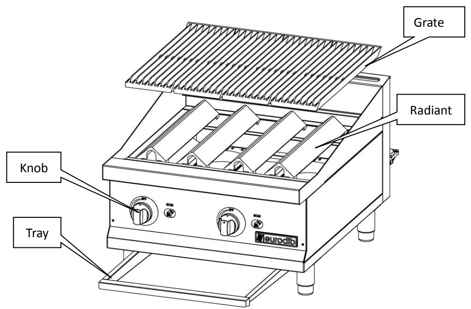
2. Pull out and remove all the knobs. Remove the tray, grates, and radiants. |

3. Remove the screws of the control panel. |
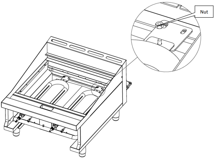
4. Remove the nuts for U burners. |
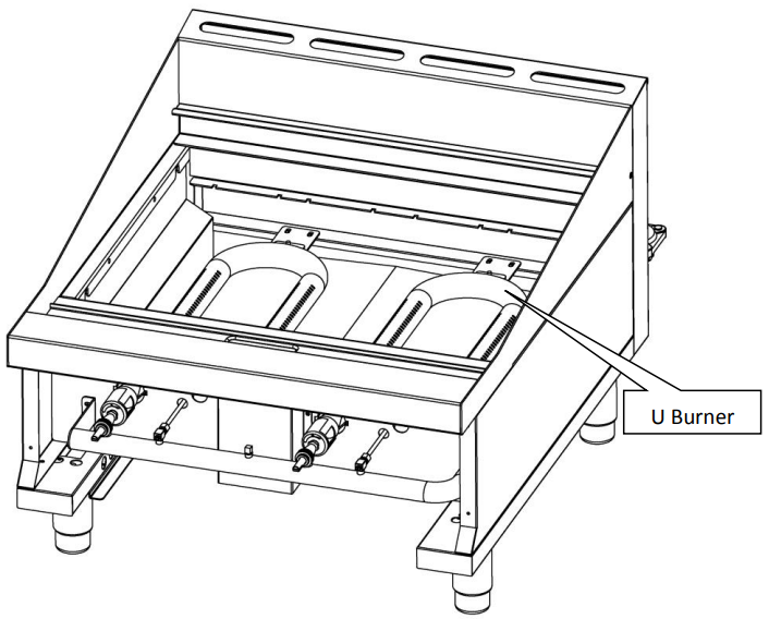
5. Remove the U burners. |
|
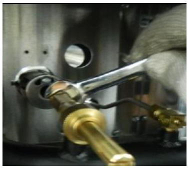
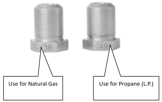
6. Remove the orifice and replace it. Use a 1/2” spanner. See the list of orifice numbers for the appropriate gas type. |
7. Converting the gas regulator.
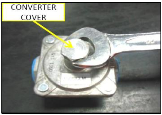
Remove the converter cover from the regulator. Use a 7/8” spanner. |
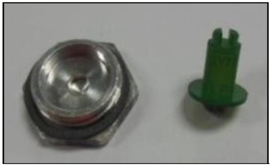
Pull out the converter from the cover. |
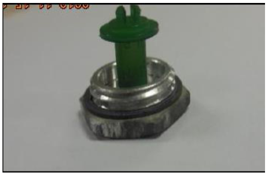
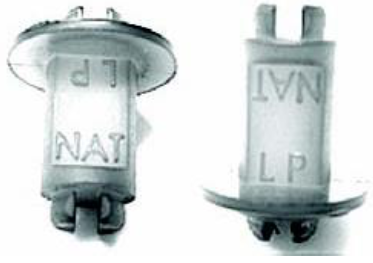
Position of the converter when using propane (L.P.). |
Install the converter cover to the regulator. |
Note: The arrow in the regulator indicates the flow direction of the gas.
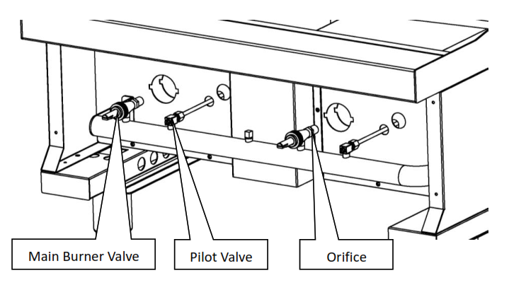
8. Reinstall the U burners.9. Check leakage and reinstall the other parts.10. Ignite the pilot burner and check the flame state.11. Turn the knobs to “High”.If the U burner does not ignite, open the pilot valve more. If the pilot flame appears larger than necessary, turn it down and reset burner ignition. The pilot flame should be as small as possible but large enough to guarantee a reliable ignition of the burners when the knobs are turned to “ON.Note: Please check leakage before reinstalling the control panel.
LIGHTING INSTRUCTIONS
Lighting the Pilot The pilot light on the appliance has been set at the factory. A screwdriver may be required for the first lighting to adjust the flame for your elevation.
- Turn off the manual valve and wait 5 minutes to clear the air gas.
- Turn all knobs to the “OFF” position.
- Hold an ignition source (match) at the pilot. When the flame is established, remove the ignition source.
- Turn the burner knobs to “ON”. If the burner does not ignite, promptly open the pilot
valve more. If the pilot flame appears larger than necessary, turn it down and reset the burner ignition. The pilot flame should be as small as possible but large enough to guarantee a reliable ignition of the burners when the knobs are turned to “ON”.Lighting the Main BurnerTo light burner, turn the knob to “ON.” Then back off to the desired flame level. The range of adjustment is virtually infinite between “ON” and “OFF”.Main burner air supplyFor efficient burner operation, a proper balance of the gas volume and primary air supply must be maintained, which will result in a complete combustion. Insufficient air supply results in a yellow streaming flame. The primary air supply is controlled by an air shutter on the front of the burner. Loosen the screws on the front of the burner and adjust the air shutter to just eliminate the yellow tips of the burner flame. Lock the air shutter in place by tightening the screws.CAUTION: Never attempt to move a grill section while cooking. An unexpected flare could cause severe injury. Turn off the unit, let it cool and use potholders and/or gloves to reposition or remove. The space between the legs at the bottom admits combustion air. DO NOT BLOCK THIS SPACE.All burners are lit from constantly burning pilots. Turning the valve to the desired flame height is all that is required to put the unit in service. Do not permit fans to blow directly at the unit. Wherever possible, avoid open windows next to the unit’s sides or back. Avoid wall-type fans, which create air crosscurrents within a room.It is also necessary that sufficient air should be allowed to enter the room to compensate for the amount of air removed by any ventilating system. Otherwise, a subnormal atmospheric pressure will occur, affecting the operation and causing undesirable working conditions.A properly designed and installed hood will act as the heart of the ventilating system for the room or area in which the unit is installed, and will leave the unit independent of changing draft conditions. All valves must be checked and lubricated periodically. This must be done by an authorized service representative in your area.
OPERATION INSTRUCTIONS
Turn the burners ON about 15-20 minutes before cooking for preheating. Set the knobs to the desired flame height or temperature. Each valve will control the gas flow to the burner to bring that area of the unit up to the set temperature. If different temperature settings are to be used, adjoining areas should be set at progressively higher temperatures using the lowest temperatures on the outside burners. A uniform and systematic approach to the loading of the unit will produce the most consistent product results.RadiantsPlace all the radiants in their position. Make sure that the radiants are setting properly into the slots on the front and rear supports. Radiants should be centered over a straight section of the burners.
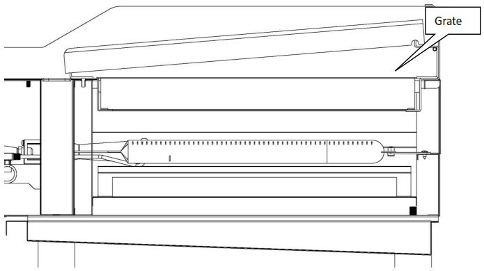
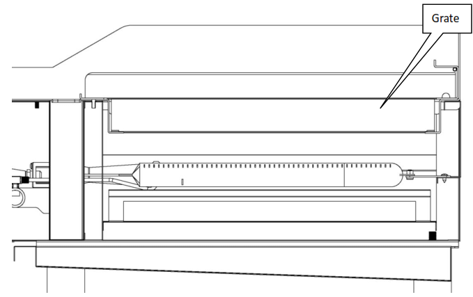
 Cooking GratesInstall the top cooking grates.NOTE: When cooking grates are placed sloping toward the front, the grooves on top will guide the excess fat drippings into the grease trough.
 |
 |
CLEANING & MAINTENANCE
Initial Cleaning Prior to operating your new charbroiler, thoroughly wash the exterior with a mild detergent or soap solution. Do not use abrasive cleaners as this might damage the cabinet finish. If the stainless steel surfaces become discolored, scrub by rubbing only in the direction of the finished grain. When the charbroiler is first heated, it will smoke until the oil used in manufacturing, preservation, and dust from storage and shipping are burned off. An hour at “max.” on all burners is usually sufficient.Daily Cleaning
- Remove the greased pan, empty it, and wash it. The grease buildup on the grates should be cleaned daily (more often as needed).
- Caution: When handling grates or radiants, always use insulated gloves to prevent burns.
- Warning: Do not cover the top of the grid grates during a burn-off operation. Restricting the airflow by covering the grid grates may cause them to warp. It will also cause damage to the valves, knobs, and front panel decal.
- Place the grates on the broiler with grid bars horizontal, facing down.
- Turn the charbroiler on for approximately 45 minutes.
- Turn off the charbroiler and allow it to cool off for 20 minutes.
- Clean the top and bottom surfaces of the grate with a wire brush to remove animal fats and carbonized grease.
- Clean the channels on the grates with a scraper.
- Remove the grates from the charbroiler. Clean the top surface of the radiants with the wire brush. They may be cleaned in place.
NOTE: Parts protected by the manufacturer or his agent are not to be adjusted by the installer unless the installer is an authorized service agent.
TROUBLESHOOTING GUIDE
| PROBLEMHeat does not come on when the valve is turned on. | POSSIBLE CAUSEThe pilot burner is not lit. |
| The gas valve is bad. | |
| The pilot burner will not light. | Obstructed pilot orifice. |
| The pilot valve is turned off. | |
| The pilot burner will not stay lit. | Obstructed pilot orifice. |
| The gas supply is not purged of air. | |
| Air is blowing the pilot’s light out. | |
| Fat appears to smoke excessively. | The heat is set too high. |
| Moisture in the food may be turning into steam. | |
| Food sticks to grates. | The heat is set too high. |
| Char broiler’s surface needs cleaning and/or seasoning. | |
| The surface under food may not have been covered with enough cooking oil. | |
| Food is undercooked inside. | The heat is set too high. |
| Food may not have been cooked long enough. | |
| Food tastes greasy or has an objectionable off-flavor. | The food itself may have an off-flavor. |
| Food may have been stored improperly before cooking. | |
| Too much fat used. | |
| _ Heat is set too low. |
| PLACE LAVA ROCK WITH AIR SPACES BETWEEN THE ROCKS. DO NOT OVERLOAD ROCK GRATES. | |
| Please use following amount of lava rock per model:T-CBL15 : 30pcsT-CBL24 : 60pcsT-CBL36 : 90pcsT-CBL48 : 120pcs | 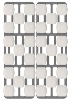 |
EXPLOSION VIEW DRAWING
MODELS: T-CBL48 / T-CBR48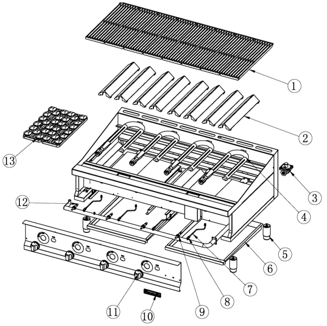
Spare Parts List
| NO. | DESCRIPTION | MODEL | CODE | QTY |
| CBL15M / CBR15M | 01.09.1050446 | 1 | ||
| 1 | Cooking Grill | CBL15M / CBR15MCBL24M / CBR24MCBL36M / CBR36MCBL48M / CBR48M | 01.03.1015028
|
2468 |
| 2 | Tent radiant | CBR15MCBR24MCBR36MCBR48M | 01.03.1015048 | 2468 |
| 3 | Regulator | CBL15M / CBR15MCBL24M / CBR24MCBL36M / CBR36MCBL48M / CBR48M | 01.22.1069501 | 1 |
| 4 | Burner | CBL15M / CBR15MCBL24M / CBR24MCBL36M / CBR36MCBL48M / CBR48M | 06.05.1470672 | 1234 |
| 5 | Foot | CBL15M / CBR15MCBL24M / CBR24MCBL36M / CBR36MCBL48M / CBR48M | 01.02.1005165 | 4 |
| 6 | Tray | CBL15M / CBR15MCBL24M / CBR24MCBL36M / CBR36MCBL48M / CBR48M | 01.05.1029395
01.05.1029318 01.05.1029365 01.05.1029318 |
1112 |
| 7 | Pilot Pipe | CBL15M / CBR15MCBL24M / CBR24MCBL36M / CBR36MCBL48M / CBR48M | 06.05.1472152 | 1234 |
| 8 | Pilot valve | CBL15M / CBR15MCBL24M / CBR24MCBL36M / CBR36MCBL48M / CBR48M | 01.20.1068509 | 1234 |
| 9 | Valve | CBL15M / CBR15MCBL24M / CBR24MCBL36M / CBR36MCBL48M / CBR48M | 01.20.1068502 | 1234 |
| 10 | Brand | CBL15M / CBR15MCBL24M / CBR24MCBL36M / CBR36MCBL48M / CBR48M | 01.02.1005449 | 1 |
| 11 | Dial | CBL15M / CBR15MCBL24M / CBR24MCBL36M / CBR36MCBL48M / CBR48M | 06.05.1472430 | 1234 |
| 12 | Orifice | CBL15M-NAT/CBR15M-NATCBL24M-NAT/CBR24M-NATCBL36M-NAT/CBR36M-NATCBL48M-NAT/CBR48M-NAT | 01.20.1068636 | 1234 |
| CBL15M- LPG/CBR15M-LPGCBL24M-LPG/CBR24M-LPGCBL36M-LPG/CBR36M-LPGCBL48M-LPG/CBR48M-LPG | 01.20.1068649 | 1234 | ||
| 13 | 12” Cast Lava Rock Kit (Optional) | CBL15M / CBR15MCBL24M / CBR24MCBL36M / CBR36MCBL48M / CBR48M | 06.05.1472465 | 1234 |
![]()
For service or Inquiry, please Call Eurodib (Toll-free) at 1 888 956 6866
Limited Warranty
Eurodib Cooking Equipment Models:
Griddles: T-G15, T-G24, T-G36, T-G48
Char Broilers: T-CBL15, T-CBL24, T-CBL36, T-CBL48, T-CBR15, T-CBR24, T-CBR36, T-CBR48
Countertop Range: T-HP212, T-HP424, T-HP636
Fryer: T-CF15, T-CF30
All new Eurodib griddles, charbroilers, fryers, and countertop range used for commercial purposes are warranted against defects in materials and workmanship under normal use and maintenance. The warranty runs for one year from the date of the original installation and is for the benefit of the original purchaser only. All other warranties, expressed or implied, statutory or otherwise, including without limitation any implied warranty of merchantability for fitness for purposes, are excluded. The seller shall in no event be liable for direct, indirect, or consequential damages in connection with Eurodib commercial products.
ExclusionsThe following conditions are not covered by warranty:
- Equipment damage or equipment failure occurs because of accident, carelessness, lack of proper set-up, supervision when required, or if the equipment is installed or operated in any manner contrary to the installation and operating instructions.
- Equipment damage or equipment failure due to improper installation, improper utility connection or supply, and problems due to ventilation.
- Equipment that has not been used appropriately, or has been subject to misuse, neglect, abuse, accident, alteration, negligence, damage during transit, delivery or installation, fire, flood, or act of God.
- Equipment that has the model number or serial number removed or altered.
- Equipment that has been changed, altered, or modified or repaired by other than an Authorized Service Agency.
Eurodib shall not be held liable for any damages to any person or property, which may result from the use of the equipment thereafter.This warranty does not apply to, and Eurodib is not responsible for any warranty claims on products sold or used outside of the contiguous United States.This equipment is intended for commercial use only. The warranty is void if the equipment is installed other than commercial applications.
[xyz-ips snippet=”download-snippet”]