Intesis Interface for the integration of Hitachi’s
Air-to-Water units User Manual

Important User InformationDisclaimerThe information in this document is for informational purposes only. Please inform HMS Industrial Networks of any inaccuracies or omissions found in this document. HMS Industrial Networks disclaims any responsibility or liability for any errors that may appear in this document.
HMS Industrial Networks reserves the right to modify its products in line with its policy of continuous product development. The information in this document shall therefore not be construed as a commitment on the part of HMS Industrial Networks and is subject to change without notice. HMS Industrial Networks makes no commitment to update or keep current the information in this document.
The data, examples, and illustrations found in this document are included for illustrative purposes and are only intended to help improve understanding of the functionality and handling of the product. In view of the wide range of possible applications of the product, and because of the many variables and requirements associated with any particular implementation, HMS Industrial Networks cannot assume responsibility or liability for actual use based on the data, examples, or illustrations included in this document nor for any damages incurred during the installation of the product. Those responsible for the use of the product must acquire sufficient knowledge in order to ensure that the product is used correctly in their specific application and that the application meets all performance and safety requirements including any applicable laws, regulations, codes, and standards. Further, HMS Industrial Networks will under no circumstances assume liability or responsibility for any problems that may arise as a result of the use of undocumented features or functional side effects found outside the documented scope of the product. The effects caused by any direct or indirect use of such aspects of the product are undefined and may include e.g. compatibility issues and stability issues.
Interface for the integration of Hitachi’s Air-to water units into KNX TP-1 (EIB) control systems.Compatible with Air-to-Water Yutaki S, Yutaki S Combi, Yutaki S80 and Yutaki M series.Application’s Program Version: 1.1
ORDER CODEINKNXHIT001A000
LEGACY ORDER CODE HI-AW-KNX-1
1. Presentation
 The INKNXHIT001A000 gateways allow fully bidirectional monitoring and control of the Hitachi Air-to-Water systems from KNX installations.
The interface is compatible with all the models of the Yutaki S line commercialized by Hitachi.
General features:
- Reduced dimensions, easy and fast installation.
- Multiple control and status objects (bit, byte, characters…) with standard KNX datapoints.
- One status object available for each control object.
- Control on the A.W. unit based on the ambient temperature read from the unit itself or from the temperature read by any KNX thermostat.
- The Hitachi A.W. can be controlled simultaneously through the remote controller of the A.W. system or through the KNX bus.
- Total supervision and control of the Hitachi A.W. unit from KNX, including unit internal variables supervision, special modes control (such as Anti-legionella), an error alarm, and codes too.
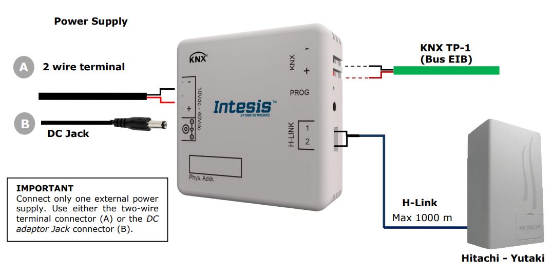
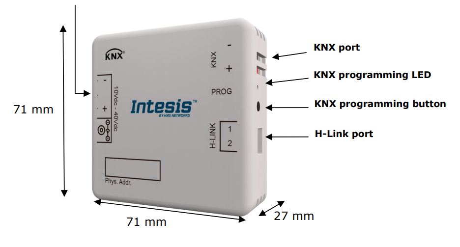
2. Connection
Connection of the interface to the AW indoor unit is by means of the cable supplied with the indoor unit to connect the remote controller. It must be connected to the interface on one side (connector H-Link) and to the internal electronic board of the Air-to-Water indoor unit on the other side.
Connection of the interface to the KNX bus is by means of the standard KNX bus connector also supplied with the interface.
In order to plug the interface into the external power supply, two different methods are available. The first one is using the external power supply provided with the interface using the DC JACK connector
Connections diagram:
3. Installation and setup
This is a fully compatible KNX device that must be configured using the ETS software. The ETS database can be downloaded from:https://www.intesis.com/products/ac-interfaces/hitachi-gateways/hitachi-knx-air-to-water-hi-aw-knx-1
Please, check the README.txt file located inside the zip file to find instructions for proper installation of the database.
![]() IMPORTANT: Do not forget to select the corresponding features of the Air-to-Water system connected to the INKNXHIT001A000 interface. This should be selected in the “Parameters” section on the ETS software.
IMPORTANT: Do not forget to select the corresponding features of the Air-to-Water system connected to the INKNXHIT001A000 interface. This should be selected in the “Parameters” section on the ETS software.
4. ETS parameters and communication objects
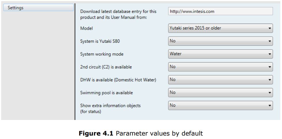
4.1 Default settings
When importing the ETS database for the first time, the following menu appears, with these parameter values selected as default:
 With this configuration is possible to control the system (Control_ objects) and monitoring it (Status_ objects) through the following communication objects:
4.1.1 Run or Stop the unit
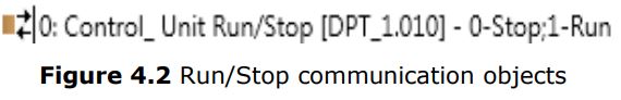 This object allows to run or to stop the Hitachi unit features (C1, C2, DHW, and/or SwimPool) at once. Sending a “0” value will turn them off while sending a “1” value will turn them on.
4.1.2 Change de Unit mode
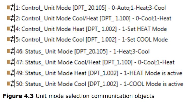 This object allows changing the working mode of the Hitachi unit. Sending a “0” value the unit will turn into “Cool” mode while sending a “1” value will make the unit turn into “Heat” mode.
4.1.3 Run or Stop the C1 Circuit
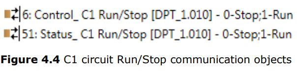
This object allows to run or to stop the Hitachi C1 Circuit (or C1 climate zone). Sending a “0” value will close the C1 circuit while sending a “1” value will open the C1 Circuit. More functions related to the C1 circuit and its communication objects can be seen in section 4.2.3.
4.1.4 Anti-legionella System
NOTE: The anti-legionella function is hidden to users by default. The installer can make it available if desired.
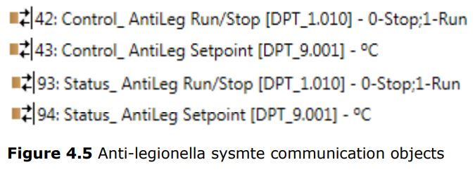 The Hitachi Yutaki S units include an Anti-legionella system. From the gateway, this function can be activated by sending a “1” value to the Control_ AntiLeg Run/Stop object and can be stopped by sending a “0” value to the same object.
It is also possible to send a value to set the temperature of the Anti-legionella system to this value. To do it so you have to use the Control_ AntiLeg Setpoint object.
![]() IMPORTANT: Anti-legionella will set the water temperature to the setting value during the specified time. This temperature will be dangerous to the user and could burn him or her. The installer is responsible for configuring it properly, advising the user, and enabling the function.
IMPORTANT: Anti-legionella will set the water temperature to the setting value during the specified time. This temperature will be dangerous to the user and could burn him or her. The installer is responsible for configuring it properly, advising the user, and enabling the function.
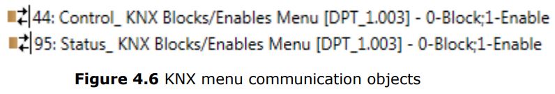 This object allows blocking or enabling the KNX menu from Hitachi’s LCD panel. Sending a “0” value will block the Menu while sending a “1” value will enable the Menu.
4.1.6 Errors and Alarms
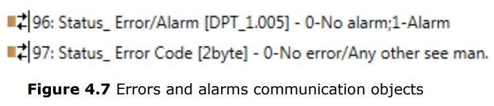
These objects allow reading the system status indicating if any alarm or error is active (Status_ Error/Alarm) and, in case it exists, it indicates which error is (Status_ Error Code). See section 7 to get more information about the error codes.
4.2 General dialog
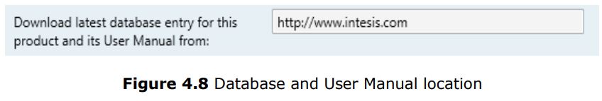
In the General Dialog (settings) tab, it is possible to enable, disable or modify the parameters shown in Figure 4.1. For instance, the first field is showing where you can download the database and the user manual from.
 4.2.1 Model
 4.2.1 Model
This parameter enables or disables communication objects depending on the Yutaki model.
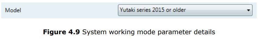
- When selecting “Yutaki series 2015 or older”, objects available will be related to Yutaki S and Yutaki S80 models from 2015 or before (default objects).
- When selecting “Yutaki series 2016 or newer”, objects available will be related to Yutaki S, Yutaki S Combi, Yutaki S80, and Yutaki M models from 2016 or later.
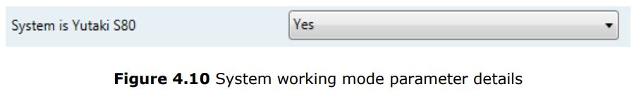
4.2.2 System is Yutaki S80
This parameter enables specific objects for Yutaki S80 and filters objects that do not apply to the Yutaki S80.
4.2.3 System working mode
 4.2.3 System working mode
This parameter enables or disables communication objects depending on the working mode selected: Water mode, Air, mode or Full (which includes both: Water and Air).
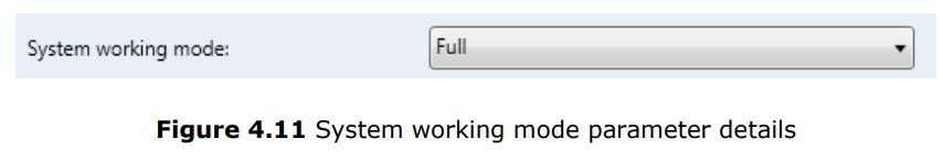
- When selecting “Water” the interface will work for a water climate environment only. Water climate control and status objects will be available. Air climate control and status objects will be disabled.
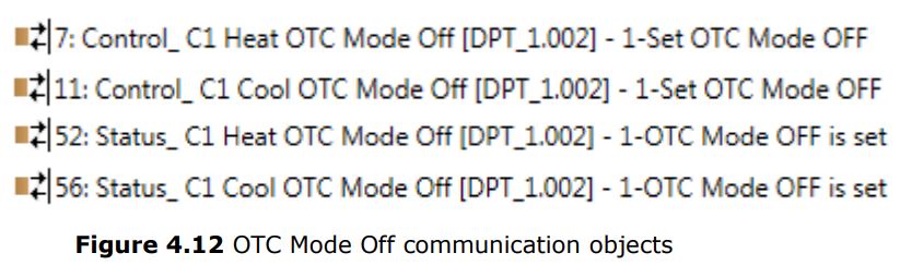
OTC ModeThe OTC model (Output Temperature Compensation) allows keeping the desired indoor temperature despite external temperature variations.
From the gateway, you can:
• Turn this function off by sending a “1” value to the Control_ C1 OTC Mode Heat/Cool Off communication object.
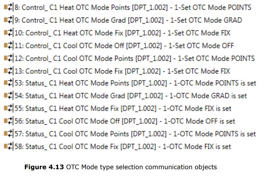
- Activate the different modes available for the calculus of the water temperature for the cooling or heating the facility where the unit is placed:
- Points: The user fixes 4 points that will create a line function that will depend on the current ambient temperature.
- Gradients: In this case, the function used is not a line but a gradient. Only available for the Heat mode.
- Fix: The temperature adjustment is only performed by a fixed value. This makes the unit keep this fixed value all the time.
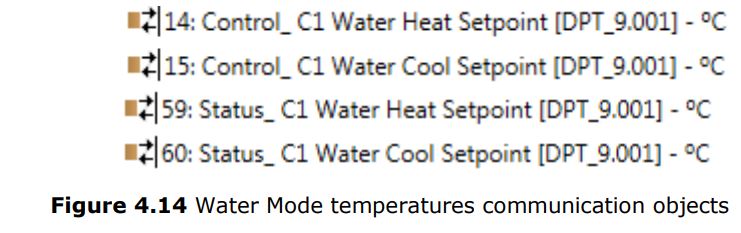
 Water mode temperaturesUsing the following communication objects it is possible to control/monitor water setpoint temperatures for the Heat and Cool modes (C1 Water Heat Setpoint and C1 Water Cool Setpoint).
- When selecting “Air”, the interface will work for an air climate environment only. Air climate control and status objects will be available. Water climate control and status objects will be disabled.
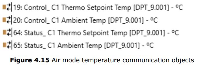
Air mode temperatures
With the communication objects corresponding to this mode enabled, control/monitoring of the setpoint temperature of the thermal (C1 Thermo Setpoint) and the ambient temperature provided by a thermostat not included in the Hitachi system (C1 Ambient Temp).
- When selecting “Full“, the interface will work for an air and water climate environment. Air and Water climate control and status objects will be available.
NOTE: If Yutaki S80 is selected, some of these communication objects may not be present.
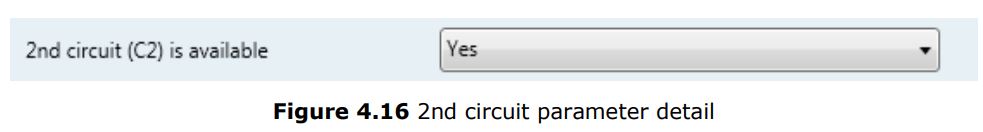
4.2.4 2nd circuit (C2) is available
This parameter enables or disables the Control_ and Status_ communication objects of a second circuit (or climate zone). In case the project is divided into 2 separate circuits this parameter needs to be selected to get control on each circuit independently.
- When selecting “No”, the gateway will hide the 2nd circuit (C2) communication objects.
- When selecting “Yes”, the gateway will show the 2nd circuit (C2) communication objects. Depending on the other selected parameters, some objects will remain hidden and some others will be shown.
- Run and Stop status:
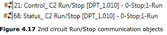
To activate or deactivate the 2nd circuit (C2) a “1” value or a “0” value needs to be sent respectively to the Run/stop communication object.
- If “Water” mode is selected:
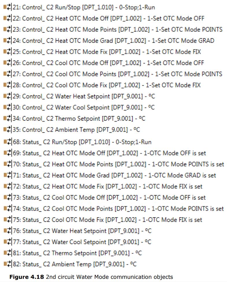
- If “Air” mode is selected:

- If the “Full” mode is selected, all communication objects present when selecting “Water” or “Air” will be enabled for this mode too.
4.2.5 DHW is available (Domestic Hot Water)
This parameter enables or disables the Control_ and Status_ objects corresponding to the control and monitoring of a water tank or DHW system.
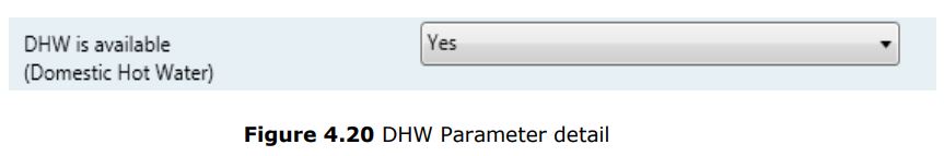
- When selecting “No“, the gateway will hide communication objects related to the water tank or the Domestic Hot Water system.
- When selecting “Yes“, the gateway will show the communication objects related to the water tank or the Domestic Hot Water system.
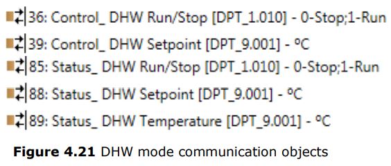
Domestic Hot WaterBy means of Control_ DHW Run/Stop and Control_ DHW Setpoint, it is possible to turn on/off the DHW system and to control its setpoint temperature.
Through the Status_ DHW Temperature communication object, it is possible to read the instantaneous temperature of the DHW system.
4.2.6 Swimming pool is available
This parameter enables or disables the Control_ and Status_ objects corresponding to the control and monitoring of a swimming pool system present in the project

- When selecting “No”, the gateway will hide communication objects related to the swimming pool.
- When selecting “Yes”, the gateway will show communication objects related to the swimming pool.
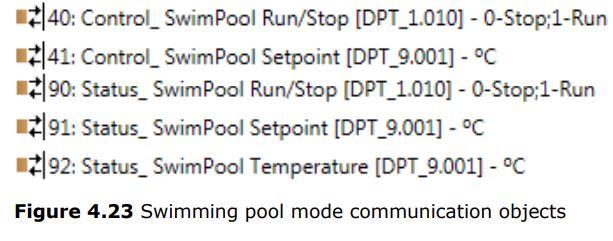
Swimming poolBy means of Control_ SwimPool Run/Stop and Control_ SwimPool Setpoint, it is possible to turn on/off the Swimming pool system and also to control its setpoint temperature.
Through the Status_ SwimPool Temperature communication object, it is possible to read the instantaneous temperature of the Swimming pool system.
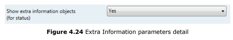
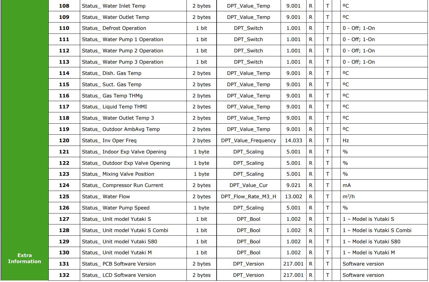
4.2.7 Show extra information objects (for Status)
 4.2.7 Show extra information objects (for Status)
These parameters enable or disable the Status_ communication objects related to the monitoring of extra information depending on the installed Hitachi model (Yutaki S or Yutaki S80).
- When selecting “No“, the gateway will hide communication objects related to the extra information provided by the Hitachi units.
- When selecting “Yes“, the gateway will offer you to select extra information for a Yutaki S80 model or the rest of the Yutaki S models.
 Yutaki S Extra Information
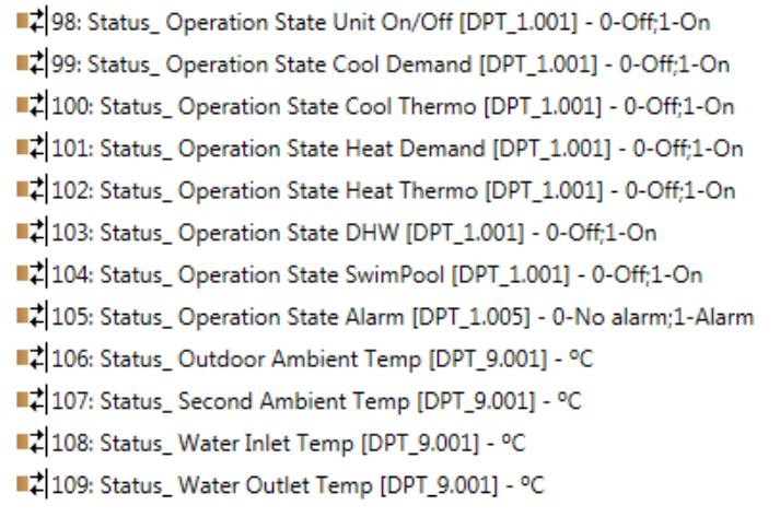
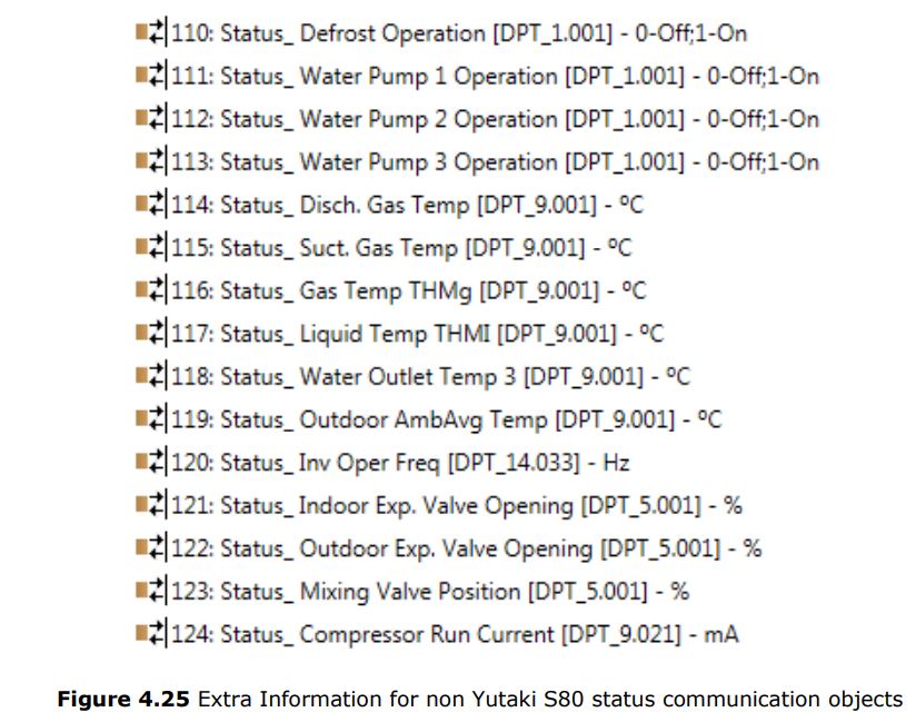
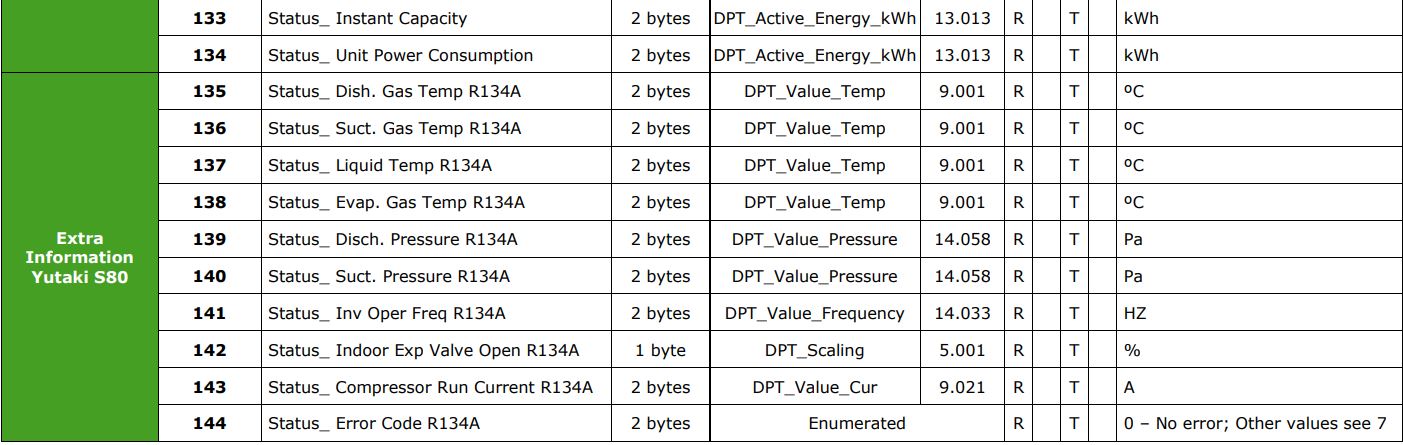
Yutaki S80 Extra Information For more details about the information provided by those communication objects, please check the Hitachi user manual.
5. Technical Specifications
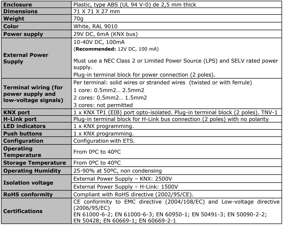
External Power Supply connection
6. Compatible Air-to-Water (A.W.) units
A list of Hitachi unit model references compatible with INKNXHIT001A000 and their available features can be found in: [PDF]
7. Error Codes object #97: Status_Error_Code.
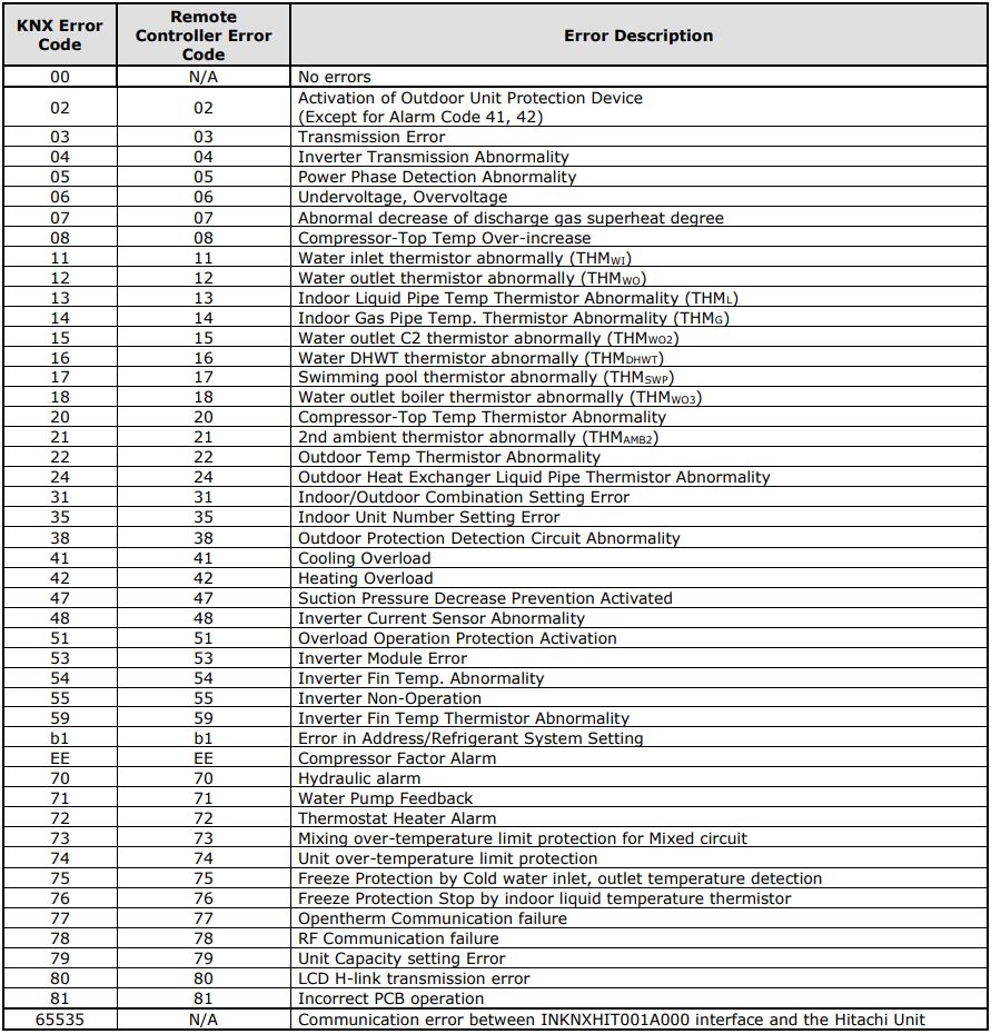
In case you detect an error code not listed, please contact your nearest Hitachi support center to get more information about the meaning of the error.
8. Error Codes object #144: Status_Error_Code_R134A.
Available only if parameter “Show extra information objects (for Status)” is set active. (See Section 4.2.7).
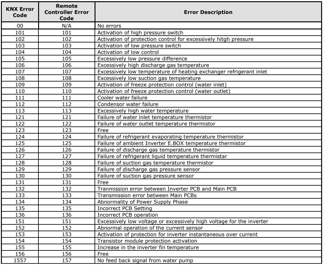
In case you detect an error code not listed, please contact your nearest Hitachi support center to get more information about the meaning of the error.
Appendix A Communication objects description table
Control Objects
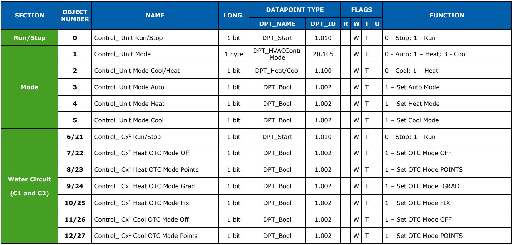
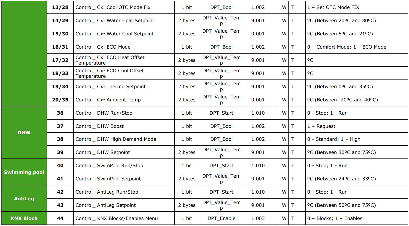
1 X can be 1 or 2 depending on which circuit is being controlled.
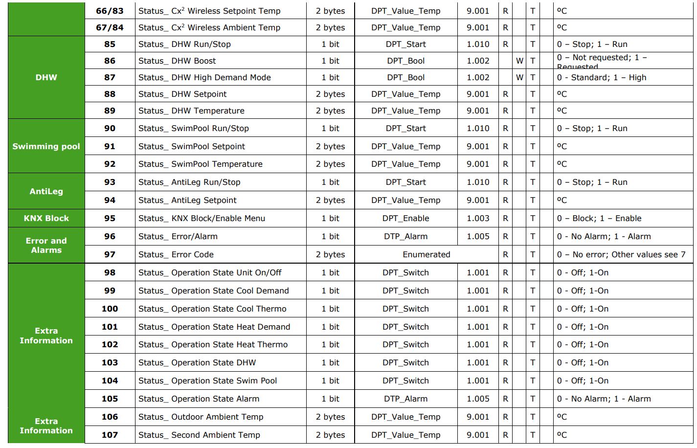
Status Objects
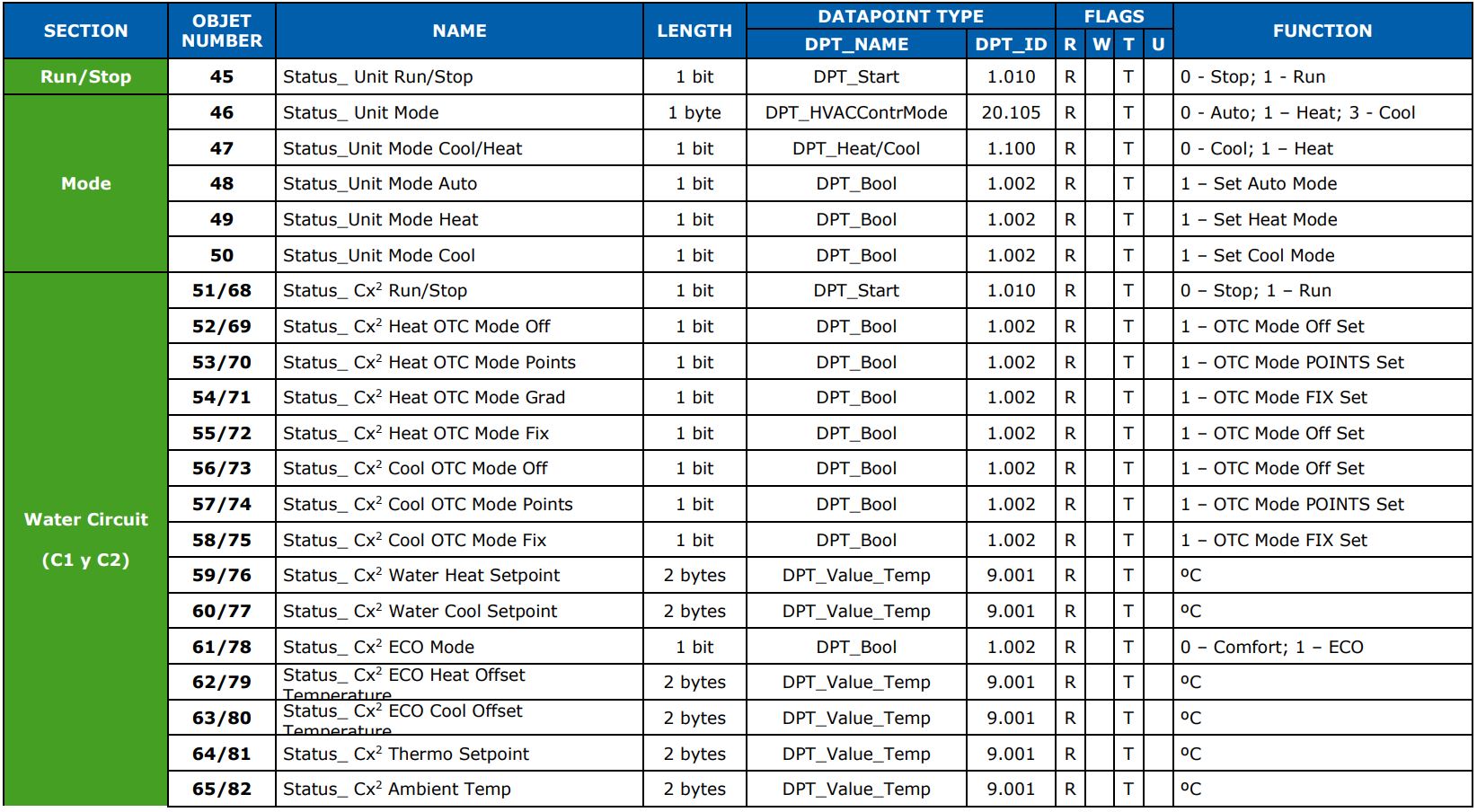
2 X can be 1 or 2 depending on which circuit is being observed.
References
[xyz-ips snippet=”download-snippet”]