Mitsubishi Heavy Industries air conditioningUser Manual
![]()
Gateway for integration of Mitsubishi Heavy Industries air conditioning systems into KNX TP-1 (EIB) control systemsApplication’s Program Version: 2.1
Intesis KNXMitsubishi Heavy Industries AC
Important User Information
Disclaimer
The information in this document is for informational purposes only. Please inform HMS Industrial Networks of any inaccuracies or omissions found in this document. HMS Industrial Networks disclaims any responsibility or liability for any errors that may appear in this document.
HMS Industrial Networks reserves the right to modify its products in line with its policy of continuous product development. The information in this document shall therefore not be construed as a commitment on the part of HMS Industrial Networks and is subject to change without notice. HMS Industrial Networks makes no commitment to update or keep current the information in this document.
The data, examples and illustrations found in this document are included for illustrative purposes and are only intended to help improve understanding of the functionality and handling of the product. In view of the wide range of possible applications of the product, and because of the many variables and requirements associated with any particular implementation, HMS Industrial Networks cannot assume responsibility or liability for actual use based on the data, examples or illustrations included in this document nor for any damages incurred during installation of the product. Those responsible for the use of the product must acquire sufficient knowledge in order to ensure that the product is used correctly in their specific application and that the application meets all performance and safety requirements including any applicable laws, regulations, codes and standards. Further, HMS Industrial Networks will under no circumstances assume liability or responsibility for any problems that may arise as a result from the use of undocumented features or functional side effects found outside the documented scope of the product. The effects caused by any direct or indirect use of such aspects of the product are undefined and may include e.g. compatibility issues and stability issues.
Gateway for integration of Mitsubishi Heavy Industries air conditioning systems into KNX TP-1 (EIB) control systems.
1. Description
1.1 Introduction
IntesisTM KNX – Mitsubishi Heavy Industries AC is a communication gateway for the integration of Mitsubishi Heavy Industries air conditioning (AC) systems into KNX TP-1 (EIB).
This gateway allows integrating a Mitsubishi Heavy Industries AC system inside a supervision/control/automation system through PLC, SCADA and, in general, through any device or system with a KNX TP-1 (EIB) interface.
The aim of this integration is to make accessible several Mitsubishi Heavy Industries air conditioning indoor units communicating with the Superlink protocol as if they were part of a KNX TP-1 (EIB) system. Therefore, the Intesis KNX acts as a KNX device in the KNX TP-1 (EIB) interface, allowing the KNX system read and write in the communication objects. Moreover, Intesis includes all hardware required to manage/control Mitsubishi Heavy Industries indoor units without extra components needed.
1.2 Integration signals
Following is the list of parameters that can be monitored/controlled on the indoor units using Intesis:
For each indoor unit in the system:
- Communication Status (read-only)
- On/Off (R/W)
- Operation Mode (R/W)
- SetPoint Temperature (R/W)
- Fan Speed (R/W)
- Remocon Lock/Unlock (R/W)
- Louver Control (R/W)
- Room Temperature (read-only)
- Filter Sign Status (read-only)
- Error Code (read-only)
- Compressor Status (read-only)
- Filter Sign Reset (write-only)
- Remocon Error Reset (write-only)
- Thermo On/Off Status (read-only)
Apart from these, the Intesis also implements some extra signals (functions):
For all indoor units1 in the system:
- HW Communication Status (read-only)
- On/Off (write-only)
- Operation Mode (write-only)
- SetPoint Temperature (write-only)
- Fan Speed (write-only)
- Remocon Lock/Unlock (write-only)
1.3 Functionality
IntesisTM continuously polls (reads) the Superlink network for all configured signals and keeps the updated status of all of them in its memory ready to be served when requested from KNX.
When a change of status is detected in a MHI’s AC signal, a write telegram is sent to the KNX bus, of the associated KNX Group.
When it is received a telegram from the KNX bus, and if its KNX Group address is associated to an MHI’s AC signal, a message is sent immediately to the Superlink network to perform the corresponding action in the MHI’s AC system.In the continuous polling if no response is detected, the corresponding virtual signal inside the gateway will be activated indicating communication error. There is a virtual signal for each AC indoor unit indicating communication error with the indoor unit – this signal will be normally activated if the indoor unit is not properly setup.
Each of the mentioned signals in section 1.2 has to be associated to a KNX group address, with this, all the system is seen as another KNX device, with the same configuration and functioning characteristics. These addresses are not fixed and can be configured using the LinkBoxEIB tool (see 4.2.2)
IntesisTM includes all hardware needed to connect directly with the Mitsubishi Heavy Industries indoor units connecting with Superlink network.
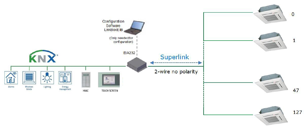
Figure 1.1 Integration of Mitsubishi Heavy Industries AC into KNX TP-1 (EIB) system
1.4 Capacity of IntesisTM
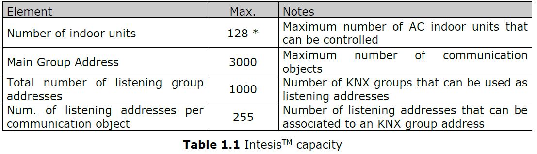
* There are two different models of IntesisTM KNX – Mitsubishi Heavy Industries AC each one with different capacity. The table above shows the capacity for the top model (with maximum capacity).
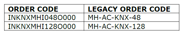
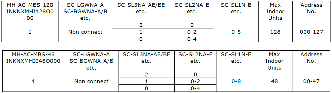
Their order codes are:
INKNXMHI048O000:
- Model supporting up to 48 indoor units
- For Superlink-I (Previous Superlink) or Superlink-II (New Superlink).
- Indoor Unit actual address range is 00 to 47
INKNXMHI128O000:
- Model supporting up to 128 indoor units
- For Superlink-II (New Superlink)
- Indoor Unit actual address range is 000 to 127
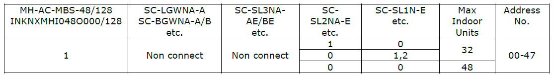
Check available combination of Mitsubishi Heavy Industries Central Control and BMS interface units in the next tables.
In the case of SL2NA or SL3NA, it is necessary to erase registration of non-connected indoor unit. For SL2NA and SL3NA, change is required for the setup deprived of the rights of instruction of Remocon control Lock/Unlock.
New Superlink connections:
Previous Superlink connections:
2. KNX interface of IntesisTM
Description
IntesisTM KNX – Mitsubishi Heavy Industries supports the KNX TP-1 (EIB) physical layer, as defined in the KNX standard. It behaves as another device of the KNX system, with the same configuration and functional characteristics as other KNX devices.
KNX TP-1 (EIB) bus provides a 30V DC current, which can even directly power certain low-consumption KNX devices. IntesisTM does not drain any significant current from the KNX bus – it has a separate own power supply. Another important electrical aspect is that the KNX TP-1 (EIB) port of IntesisTM is optically isolated (~2500Vrms AC) from all its other ports (EIA232, EIA485, Ethernet) and power supply.
At a logical level, all KNX devices feature an interface of communication objects, by which their functionality is abstracted. As a basic example, a KNX interface of an AC indoor unit would typically consist of an interface of datapoints such as “On/Off”, “Setpoint temperature”, “Operating mode”, etc.
Associations between communication objects from different KNX devices are actually done by means of so-called group addresses.
KNX telegrams within a working KNX installation are always addressed to a certain KNX group address. Typically, whenever a communication object on a KNX device changes its value, the new value is updated to the bus, by sending a “write” telegram addressed to its associated group address. The rest of KNX devices in the installation that have a communication object associated to this group address will act accordingly on reception of the new value.
Other operations are possible. KNX devices can also decide to read the current value of the communication objects, by sending a “read” telegram to a certain group address (previously known to be associated to the targeted comm. object). This operation is performed by many devices on bus start-up or recovery – in this way, the device gets the latest value of the group addresses it has associated right from its start-up.
Each datapoint defined in IntesisTM KNX configuration needs at least a single KNX group address associated with it. This group address will be used either for sending updates to KNX of the datapoint value (that have been generated on the other MHI interface of the IntesisTM), or receiving updates from KNX of the datapoint value (that will be propagated to the MHI side in this case)From the point of view of KNX functionality, each datapoint of IntesisTM can hold following group address associations:
- A single KNX group address with which update/write telegrams will be sent, whenever the datapoint changes (as a result of a change coming from the other interface of IntesisTM, MHI in this case).
- One or more KNX group addresses from which this datapoint of IntesisTM will be updated/written from the KNX installation (resulting in a change to the other side of IntesisTM, MHI in this case).
A single KNX group address from which IntesisTM will read the object value on KNX bus recovery / IntesisTM start-up.
Behavior of IntesisTM datapoints with regard to their associated group addresses is defined by means of flags (R, W, T, U and U2), explained in section 4.2.2.
Additional to the binding aspect commented above, it is also important to notice that each KNX communication object has a defined EIS type. The EIS type of a communication object defines the bit length and coding of the data it represents. Communication objects associated by means of a group address need to match the same EIS type, in order to communicate consistently.
So, at configuration time it is required that for each datapoint configured on IntesisTM an EIS type is defined. Datapoints on IntesisTM KNX support the following EIS-types:
- EIS1 – Switching (1bit raw)
- EIS2 – Dimming (4bit raw)
- EIS5 – Value (16bit – floating type)
- EIS6 – Scaling (8bit – scaled 0%-100% in values 0-255)
- EIS7 – Drive Control (1bit raw)
- EIS8 – Priority (2bit raw)
- EIS9 – IEEE 754 float (32bit – floating type)
- EIS10 – 16bit Counter (16bit raw)
- EIS11 – 32bit Counter (32bit raw)
- EIS13 – ASCII char (8bit raw)
- EIS14 – 8bit Counter (8bit raw)
ETS3 or ETS4 software tools are not used to configure IntesisTM. Though, it’s typical that the choice of which KNX group addresses to use is restricted or defined by an ETS-based project. If that’s the case, the KNX installer/integrator needs to provide the set of group addresses prior to doing the configuration of datapoints in LinkBoxEIB.
Also, a dummy ETS application is provided by HMS Networks (section 5), which can be imported into ETS. This application is nor downloadable into IntesisTM KNX neither usable for IntesisTM configuration. Rather, it poses as a means of having a device in the ETS project representing the IntesisTM KNX and its own datapoints/communication objects, and to which group addresses are associated.
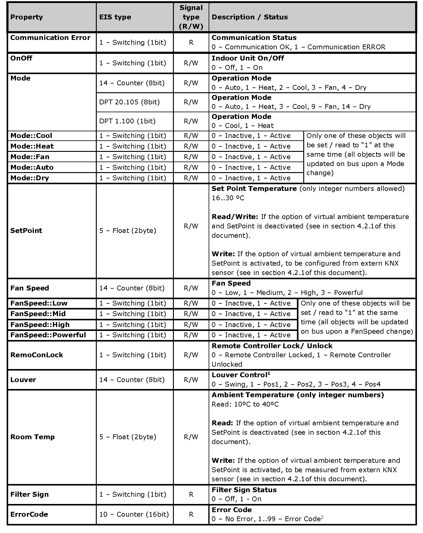
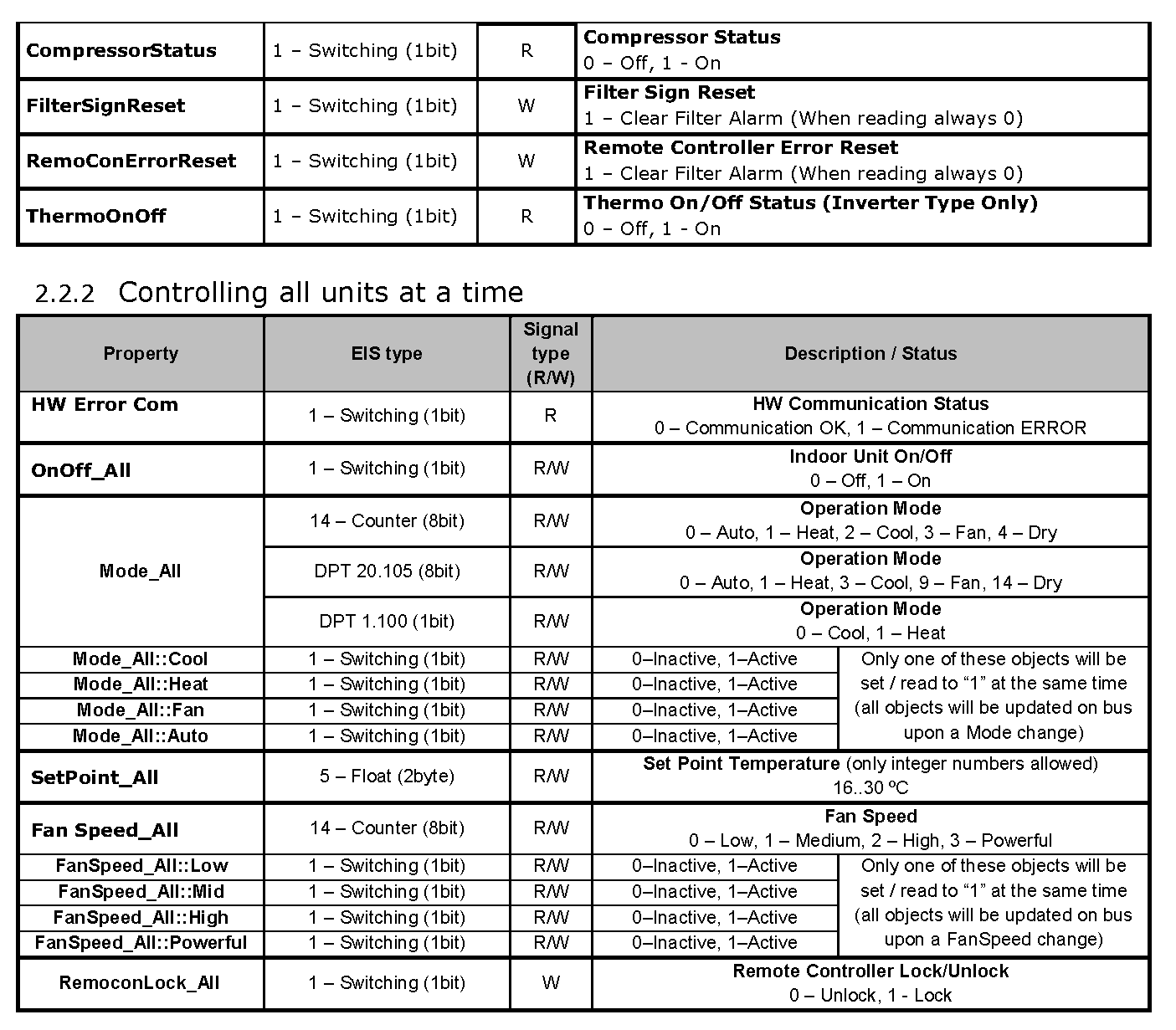
2.2 Communication objects available
Address map is configurable for each indoor unit and can be modified through the supplied software LinkBoxEIB. Next, there are two tables showing different datapoints/communication objects available either for each indoor unit control or all indoor units control at a time. Please, remember that in the tables R/W stands for Read and Write, R stands for Read Only and W stands for Write Only.
2.2.1 Communication objects per each indoor unit:
3. IntesisTM KNX Device Connections

3.1 Connect to Mitsubishi Heavy Industries Interface
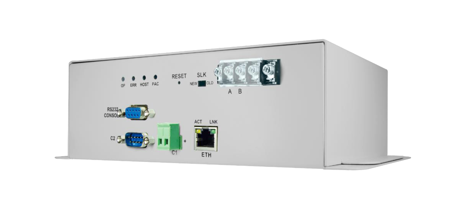
Use the A-B connector in the right top corner of the front side of the IntesisTM device in order to connect the Mitsubishi Heavy Industries network (Superlink) to the IntesisTM. Recommended specifications of the cable for the Superlink are shown as follows:
- Size of cable : 0.75 to 1.25 square mm
- Max length of wiring : total 1000m (loop wiring is not allowed)
- Cable materials :
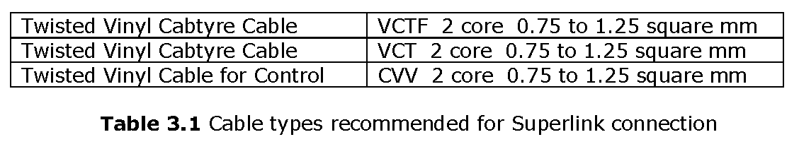
- For prevention of electromagnetic noise malfunctions, parallel wiring with the power line should be avoided
Select the appropriate Superlink mode in the SLK selector. If you are using latest Air Conditioner of the Mitsubishi Heavy Industries network (New Superlink) select NEW, if not select OLD.
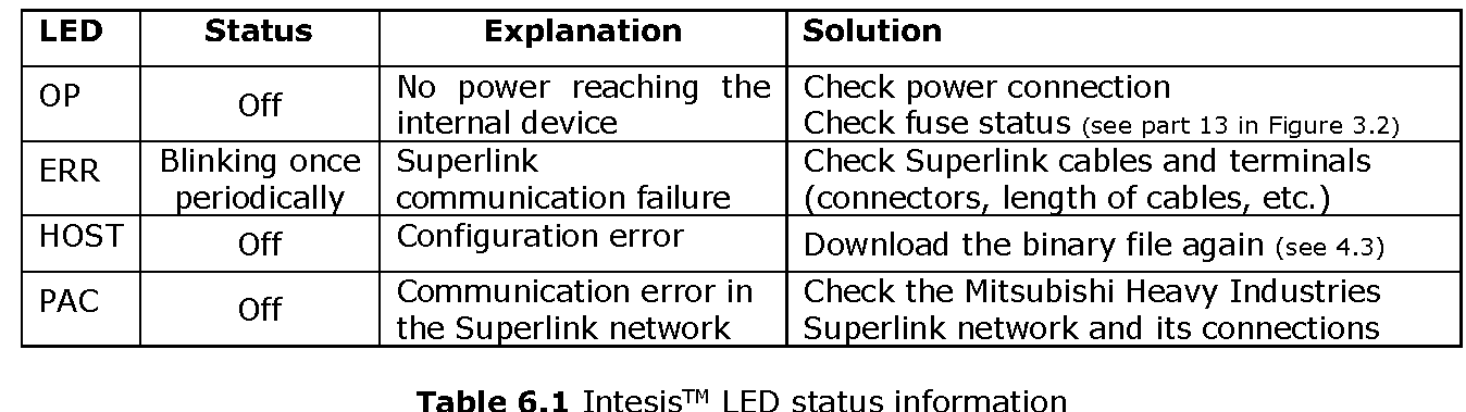
LEDs placed in the top left corner will show connection status as follows:
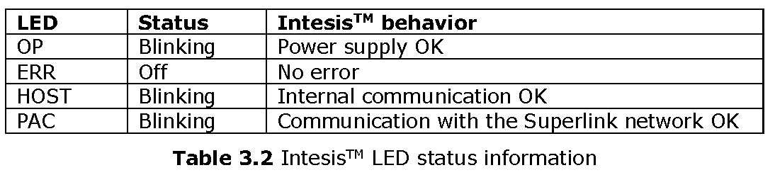
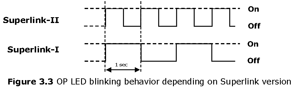
OP LED behavior must defer depending on the Superlink version, as shown in Figure 3.3
If LEDs (except ERR) are not in the states described above, check section 6.3.For further information about the Superlink network, look up the Mitsubishi Heavy Industries Manual or contact your nearest Mitsubishi Heavy Industries supplier.
Connect to KNX Interface
Connect + and – terminals of the KNX bus to the IntesisTM KNX connector (C1). The polarity is important.
How to check if there is communication with the KNX bus is explained in the LinkBoxEIB Manual (section 6.3).
To check connectivity and correct functioning, use LinkBoxEIB software (see LinkBoxEIB User Manual).
Connect to PC (LinkBoxEIB)
This action allows the user to have access to configuration and monitoring of the device (more information can be found in the LinkBoxEIB User Manual).Two methods to connect to the PC can be used:
- Ethernet: Using the ETH port (Figure 3.1) of IntesisTM. How to check connectivity is explained in section 6.3.
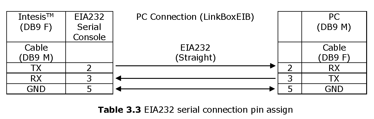
- Serial cable: Connect the IntesisTM device to the PC serial port using the serial cable provided. One end should be connected to the Console EIA232 port of the IntesisTM device (Figure 3.1) and the other end to the PC serial port.
3.4 Power Device
To power up the device, what you need is to plug properly the Power Supply connector to the IntesisTM device using a proper cable and connecting one end to the power supply connector (see Figure 3.2) and the other end to the power line. After that, just press the power supply On/Off button to turn it on.
4. LinkBoxEIB.
Configuration & monitoring tool for IntesisTM KNX series
4.1 Introduction
LinkBoxEIB is a Windows® compatible software developed specifically to monitor and configure IntesisTM KNX series.The installation procedure and main functions are explained in the LinkBoxEIB User Manual. This document can be found in the Doc folder or can be downloaded from the link indicated in the installation sheet supplied with the IntesisTM device.
In this section, only the specific case of Mitsubishi Heavy Industries indoor unit’s integration to KNX networks will be covered.
4.2 Connections configuration
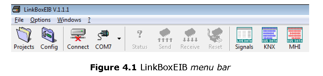
To configure the IntesisTM connection parameters and to see the points list, press on the Config button in the menu bar (see Figure 4.1). The Mitsubishi Heavy Industries Configuration window will open (see Figure 4.2). For integrations with large number of points, there is available an alternative CSV installation procedure explained in the LinkBoxEIB User Manual.
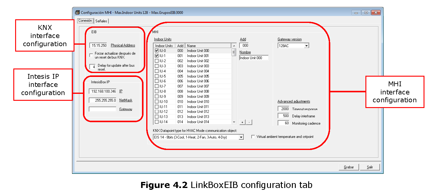
4.2.1 Configuration tabSelect the Connection tab to configure the connection parameters. Three subsets of information are shown in this window: EIB (KNX interface), Intesis IP (IP interface for configuration) and Mitsubishi Heavy Industries interface parameters (see Figure 4.2).
Next, there is an explanation for each of the configuration parameters in each mode.
- KNX interface configuration parameters:

x in “Indoor Unit xxx”) is the reference that will be used later on (in tab “Signals”) to refer to this AC indoor unit. You can also change the description name of the Indoor Unit and its address to facilitate integration tasks using Add and Name text boxes.
2. Add: Enter here the desired Indoor Unit address.
3. Name: Enter here the desired descriptive Indoor Unit name (optional).
4. KNX Datapoint type for HVAC Mode communication object: Select the desired codification so the Mode object matches your integration needs.
5. Gateway version: Selection of the IntesisTM KNX – Mitsubishi Heavy Industries gateway you are setting up (128AC for INKNXMHI128O000, 48AC for INKNXMHI048O000).
6. Timeout response: Maximum amount of time permitted before activating the Communication Error signal. It is expressed in milliseconds (ms) and ranges can vary from 2000 ms to 10000 ms.
7. Delay interframe: Maximum amount of time permitted between End Of Transmission (EOT) and a new frame. It is expressed in milliseconds (ms) and ranges can vary from 500 ms to 3000 ms.
8. Monitoring cadence: Cadence of monitoring and subscription. It is expressed in seconds (s) and ranges can vary from 60 s to 600 s.
9. Virtual ambient temperature and setpoint: Meant to be enabled when you want the temperature provided by a KNX sensor to be the reference ambient temperature for the air conditioner. Then, the following formula applies for calculation of real Control_ Setpoint Temperature sent to the AC unit:
“AC Setp. Temp” = “AC Ret. Temp” – (“KNX Amb. Temp.” – “KNX Setp. Temp”)
- AC Setp. Temp: AC indoor unit setpoint temperature
- AC Ret. Temp: AC indoor unit return temperature
- KNX Amb. Temp.: Ambient temperature provided from KNX
- KNX Setp. Temp: Setpoint temperature provided from KNX
As an example, consider the following situation:User wants: 19ºC (“KNX Setp. Temp.”)User sensor (a KNX sensor) reads: 21ºC (“KNX Amb Temp.”)Ambient temp. read by MHI system is: 24ºC (“AC Ret. Temp”)In this example, the final setpoint temperature that INKNXMHI048O000/128 will send out to the indoor unit (shown in “Setp. Temp.”) will become 24ºC – (21ºC – 19ºC) = 22ºC. This is the setpoint that will actually be requested to MHI unit.
This formula will be applied as soon as the Control_ Setpoint Temperature and Control_ Ambient Temperature objects are written at least once from the KNX installation. After that, they are kept always consistent.
Note that this formula will always drive the AC indoor unit demand in the right direction, regardless of the operation mode (Heat, Cool or Auto). Due to the use of this functionality, temperature showed in the KNX device and in the MHI remote controller (in case it exist) may differ.
Additional configuration parameters should generally be left to their default value. They only might need to be tuned in some very specific cases (installations with large number of units, scenarios with large bursts of commands sent at once …)
4.2.2 Signals
Select the Signals tab to configure the signals list (the IntesisTM internal points).
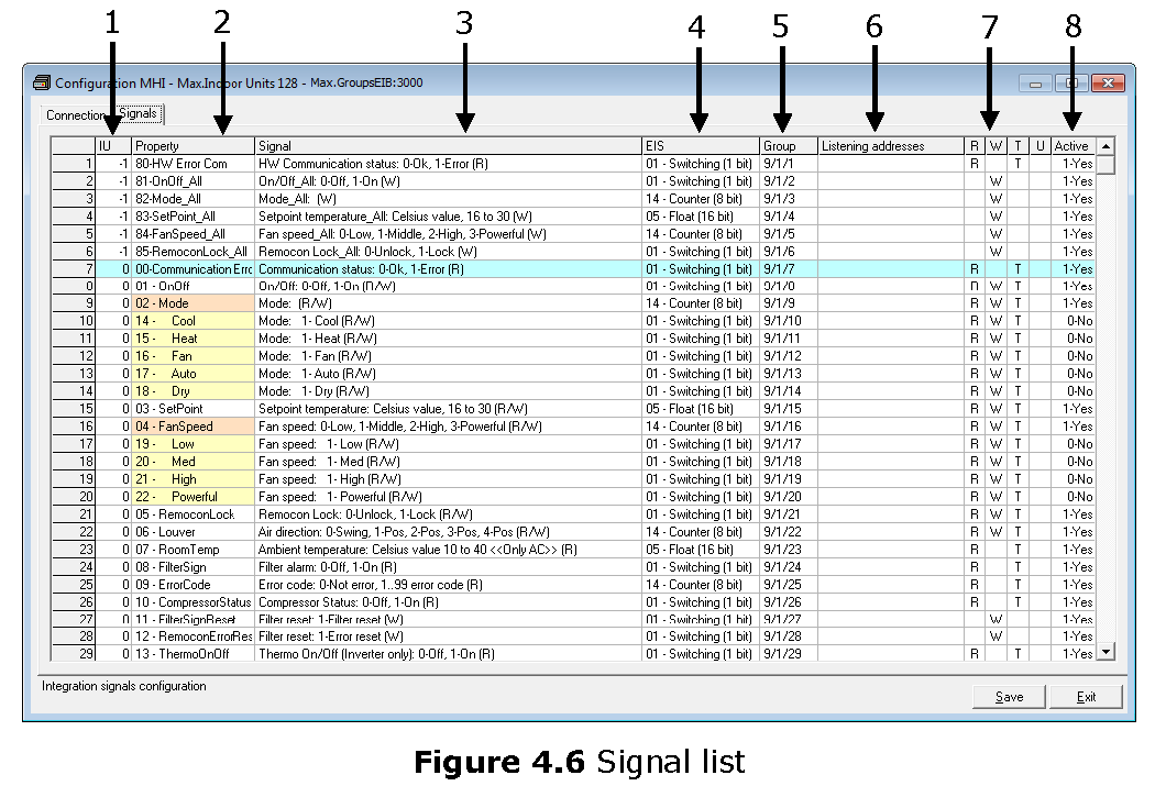
- IU: Indoor Unit identifier.
- Property: Identifies the different signals available per every MHI group. An identification code is given to every different signal into the MHI group, identifying every signal with an individual code. In section 2.2, an explanation of every signal is given. A contextual menu appears using mouse right button click over the column showing all the possible signal codes.
- Signal: Signal’s descriptive name (optional). Useful to identify the signal. The default descriptive name corresponds to the signal’s code, but can be edited or modified.
- EIS: KNX data type (Data point) to encode the signal’s value. It will depend on the MHI type of signal associated to it in every case. Edit using the mouse right-button-click pop-up menu available on the column. Only the EIS defined in values are allowed.
- Group: Main KNX group address for the signal. Flags R,W,T,U explained below will only apply for this main KNX group address, not for listening addresses. Formats supported are P/I/S and P/S.
- Listening addresses: KNX group addresses that will be listened by IntesisTM for this signal. If IntesisTM receives a KNX telegram whose destination is one of these listening addresses, the telegram will be taken into account and the corresponding action will be performed on this signal (if W is active). Formats supported are P/I/S and P/S, comma separated.
- Communication object flags:7.1 R: Indicates if this signal is allowed to be read from KNX system (“R” flag activated, “blank” flag not activated).7.2 W: Indicates if this signal is allowed to be written from KNX system (“W” flag activated, “blank” flag not activated).7.3 T: Indicates if this signal will generate a telegram sending to the KNX system following a change of the signal’s value, that is to say, any change of value of this signal in MHI side will be transmitted to the KNX system if this flag is activated (“T” flag activated, “blank” flag not activated).7.4 U: Indicates if this signal will be updated (sending read requests) whenever IntesisTM starts up or after a KNX bus reset (“U” flag activated for the main group address, “U2” activated for the listening group address, “blank” flag not activated).1
- Active: Indicates if the signal is active or not for the current configuration (“1-Yes” signal active, “0-No” signal not active).
See section 2.2 for further detail on available signals and the possible values on each one.
4.3 Sending the configuration to IntesisTM
When the configuration is finished, follow the next steps.
- – Click on Save button to save the project to the project folder on your hard disk (more information in LinkBoxEIB User Manual).
- – You will be prompted to generate the configuration file to be sent to the gateway.a.- If Yes is selected, the binary file (MHI.Lbox) containing the configuration for the gateway will be generated and saved also into the project folder.b.- If NO is selected, remember that the binary file with the project needs to be generated before the IntesisTM starts to work as expected.
- – Once in the configuration window again, click on exit. Configuration file is ready to be sent to the IntesisTM device.
- -Press the Send File button to send the binary file to the IntesisTM device. The process of file transmission can be monitored in the IntesisTM Communication Console window. IntesisTM will reboot automatically once the new configuration is loaded.After any configuration change, do not forget to send the configuration file to the IntesisTM using button Send File.
4.4 Signals viewer
Once the gateway is running with the correct configuration, to supervise the status of the configured signals, press the Signals button on the menu bar (see Figure 4.1). The Signals Viewer window will open (see Figure 4.7).
This window shows all signals active within the gateway with its main configuration parameters and its real time value2 in the Value column.
- DO NOT BE CONFUSED: Philosophy of IntesisTM point’s U flag is not the same as KNX device’s U flag. In KNX devices, U flag means that the point’s value will be updated whenever a write telegram for the group address is received by the device.
- In case you connect to the IntesisTM when it’s been running for a certain time, you should press the Refresh button to get updated values. After pressing Refresh, all signal values will keep continuously updated until the connection is closed.

The signals viewer can be used even though only one system is connected to the IntesisTM, KNX or Mitsubishi Heavy Industries AC. Therefore, it becomes convenient for supervision and testing the system.
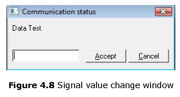
In order to force a specific value to a signal, double-click its row in the table. This will display a dialog in which the desired value can be entered (see Figure 4.8). Changing its value in this way, will make:
- The content of the corresponding KNX group address will be changed to this value.
- If the signal is write-enabled, it will trigger a suitable command to Mitsubishi Heavy Industries AC system.
4.5 Files
LinkBoxEIB saves the integration configuration in the following files inside the project folder:
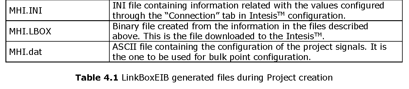
It is strongly recommended to back up the project folder containing these files in external media, once the installation process is finished. This way you will be able to do future configuration changes in case of reinstallation of LinkBoxEIB due, for example, to a failure of the hard disk in the PC where LinkBoxEIB was installed.
The configuration cannot be uploaded from the gateway to LinkBoxEIB, it can only be downloaded.
5. IntesisTM and ETS
5.1 Integration of IntesisTM in ETS
As explained the IntesisTM is configured with the LinkBoxEIB but in some projects it might be needed to integrate the gateway in the ETS project, for example to allow the line couplers have a correct configuration of their filter tables. To do so a Dummy device can be used in ETS to simulate the IntesisTM and associate also to this Dummy device all group addresses used in IntesisTM.The dummy device can be downloaded from: https://intesis.com/docs/software/setupv_linkboxmb
6. Setup process and troubleshooting
6.1 Pre-requisites
It is necessary to have the KNX bus operative and well connected to the KNX port of IntesisTM.
Connectors, connection cables, PC for LinkBoxEIB, and other auxiliary material, if needed, are not supplied by HMS Networks for this standard integration. Items supplied by HMS Networks for this integration are:
- IntesisTM KNX device with full Mitsubishi Heavy Industries AC compatibility without extra components.
- Standard plug-in 220Vac 50Hz power supply to power IntesisTM (European plug type).
- Access to LinkBoxEIB software download site to configure IntesisTM.
- Console cable needed to download the configuration to IntesisTM.
- Product documentation.
6.2 Setup procedure
- Install LinkBoxEIB on your laptop, use the setup program supplied for this and follow the instructions given by the Installation Wizard.
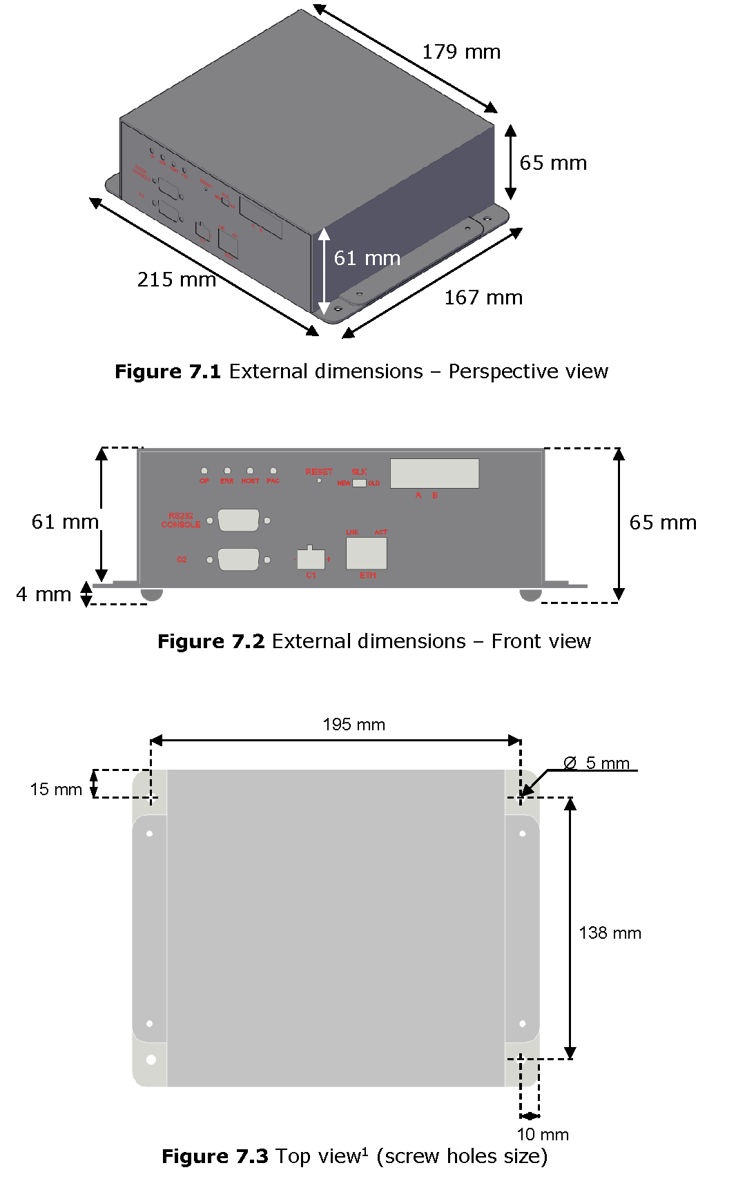
- Install IntesisTM in the desired installation site. For your convenience, check external enclosure measures (see 7) before deciding where to place the IntesisTM device.
- Connect the communication cable coming from the KNX bus to the IntesisTM KNX port (See 3 for more information on connection procedure).
- Connect the Superlink network cable to the IntesisTM port marked as AB (see 3.1).
- Select the appropriate Superlink mode in the SLK selector. If you are using latest Air Conditioner of the Mitsubishi Heavy Industries network select NEW, if not select OLD. Contact your nearest Mitsubishi Heavy Industries supplier in case of doubt.
- Connect the IntesisTM device to the power line (see 3.4) and press the On/Off button to turn it on.
- Connect the communication cable coming from the serial port of your laptop/desktop PC to the IntesisTM port marked as EIA232 Console (see 3.3).
- Open LinkBoxEIB and proceed as explained in section 4.
6.3 Troubleshooting
If IntesisTM is not working properly or even not working at all, please check the following conditions to be accomplished.
6.3.1 Physical checkingFirst point to look at to make sure that IntesisTM is not working properly is to check physical connections:
- Make sure that the power plug is correctly connected and current is available in the power line.
- Check IntesisTM LED status:
6.3.2 Software checkingOnce physical connections have been checked, if functioning problems still remain, please use the LinkBoxEIB tool to monitor the working status of the device.
- To check the KNX communication status, click on the KNX button in the menu bar (see Figure 4.1).
- To check the MHI communication status, click on the MHI button, also in the menu bar (see Figure 4.1).
- To check the signal values in the KNX communication objects, click on the Signals button, also in the menu bar (see Figure 4.1).
Further information regarding the monitoring procedure and the information provided in each window can be consulted in the LinkBoxEIB Manual.
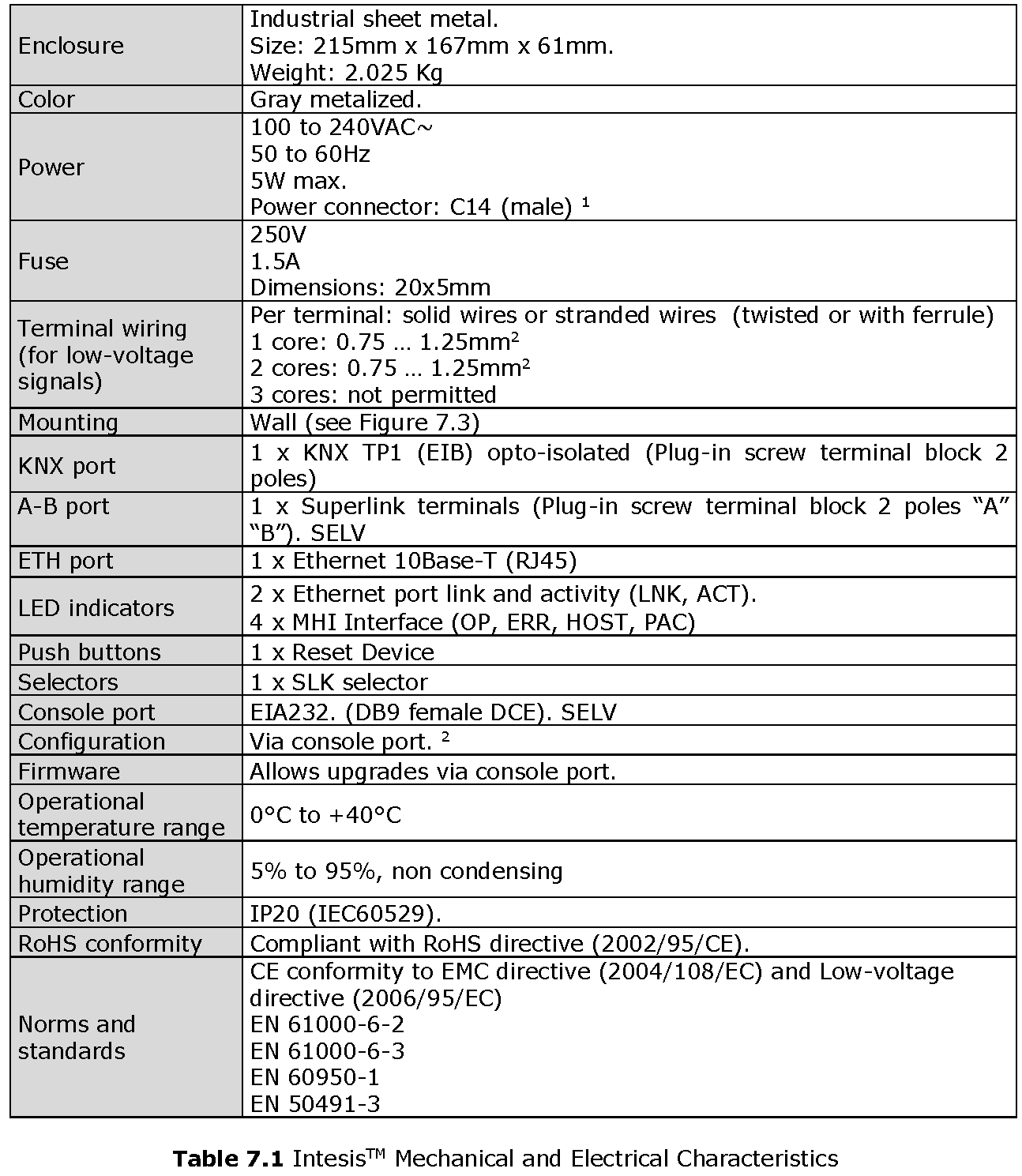
7. Mechanical & Electrical characteristics
8. AC Unit Types compatibility
Indoor units compatible with the IntesisTM KNX – Mitsubishi Heavy Industries are those included in the Mitsubishi Heavy Industries KX family and so on.
9. Error codes
This list contains all possible values shown in KNX communication objects for “Error Code” for each indoor unit.
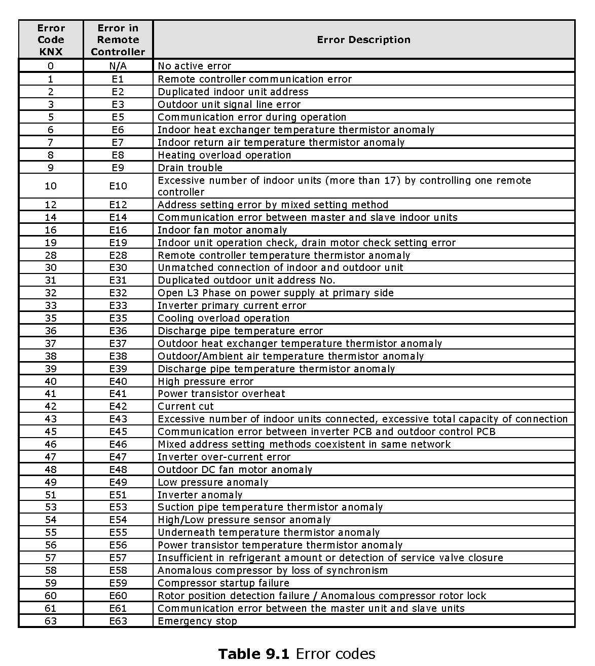
In case you detect an error code not listed, contact your nearest MITSUBISHI HEAVY INDUSTRIES technical support service.
References
[xyz-ips snippet=”download-snippet”]