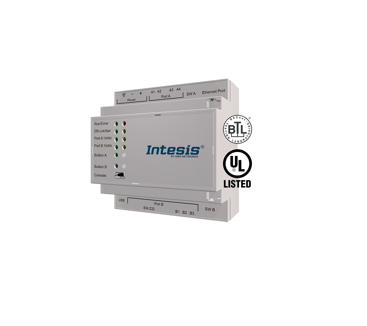
Intesis Hitachi VRF to BACnet Server gateway
SAFETY INSTRUCTIONS
![]() WARNINGFollow carefully this safety and installation instructions. Improper work may lead to serious harmful for your health and also may damage seriously the Intesis gateway and/or any other equipment connected to it.
WARNINGFollow carefully this safety and installation instructions. Improper work may lead to serious harmful for your health and also may damage seriously the Intesis gateway and/or any other equipment connected to it.
The Intesis device must be installed by accredited electrician or similar technical personnel, following all the safety instructions given here and in accordance always with the country legislation for installation of electric equipment.
The Intesis device cannot be installed outdoors or exposed to direct solar radiation, water, high relative humidity or dust.
The Intesis gateway must only be installed in a restricted access location.In case of wall mount, fix firmly the Intesis gateway on a not vibrating surface following the instructions next.
In case of DIN rail mount fix the Intesis device properly to the DIN rail following the instructions below.
Mounting on DIN rail inside a metallic cabinet properly connected to earth is recommended.
Disconnect always power of any wires before manipulating and connecting them to the Intesis gateway.
A power supply with an NEC Class 2 or Limited Power Source (LPS) and SELV rated is to be used.
Respect always the expected polarity of power and communication cables when connecting them to the Intesis gateway.
Supply always a correct voltage to power the Intesis gateway, see details of voltage range admitted by the device in the technical characteristics below.
CAUTION: Risk of Explosion if Battery is replaced by an Incorrect Type. Dispose of Used Batteries according to the instructions. Battery replacement shall be done by an authorized installer.
CAUTION: The device is to be connected only to networks without routing to the outside plant, all communication ports are considered for indoor only and can be connected SELV circuits only.
This device was designed for installation in an enclosure. To avoid electrostatic discharge to the unit in environments with static levels above 4 kV, precautions should be taken when the device is mounted outside an enclosure. When working in an enclosure (ex. making adjustments, setting switches etc.) typical anti-static precautions should be observed before touching the unit.Safety instructions in other languages can be found at https://intesis.com/docs/manuals/v6-safety
CONFIGURATION
Use the Configuration Tool to configure the gateway.See instructions to download and install the latest version at: www.intesis.com/docs/software/intesis-maps-installerUse the Ethernet connection or the Console Port (mini USB type B connector included) to get communication between the gateway and the configuration tool.Follow instructions of the user’s manual for more details.
INSTALLATION
Follow instructions next to properly install the gateway.Disconnect from mains the power supply before connecting it to the Intesis device.Disconnect power of any bus or communication cable before connecting it to the Intesis gateway.Mount the Intesis device on the wall or DIN rail following the instruction given below, respecting the safety instructions given above.Connect a NEC Class 2 or Limited Power Source (LPS) and SELV rated power supply to the Intesis gateway, respect the polarity if DC power or Line and Neutral if AC power. Apply always a voltage within the range admitted by the Intesis gateway and of enough power (see technical characteristics).Circuit-breaker must be used before the power supply. Rating 250V6A.Connect the communication cables to the Intesis device, see details on the user’s manual.Power the Intesis gateway and the rest of devices connected to it.
NOTE: The device cannot be installed in air-handling space.
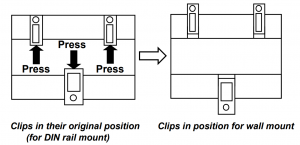
Wall Mount
- Separate the fixing clips in the bottom of the box, pushing them to the outside until hear the “click” which indicates that now the clips are in position for wall mount, see in the figure below.
- Use the holes of the to fix the box in the wall using screws.Use the template below for the wall wholes.

DIN Rail Mount
With the clips of the box in their original position, insert first the box in the upper edge of the DIN rail and later insert the box in the down part of the rail, using a small screwdriver and following the steps in the figure below.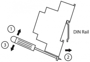
CONNECTIONS
Power SupplyMust use NEC Class 2 or Limited Power Source (LPS) and SELV rated power supply.
If using DC power supply:Respect polarity applied of terminals (+) and (-). Be sure the voltage applied is within the range admitted (check table below). The power supply can be connected to earth but only through the negative terminal, never through the positive terminal.
If using AC power supply:Make sure the voltage applied is of the value admitted (24 Vac). Do not connect any of the terminals of the AC power supply to earth, and make sure the same power supply is not supplying any other device.
Ethernet / BACnet IP (UDP) / Console (UDP & TCP)Connect the cable coming from the IP network to the connector ETH of the gateway. Use an Ethernet CAT5 cable. If communicating through the LAN of the building, contact the network administrator and make sure traffic on the port used is allowed through all the LAN path (check the gateway user manual for more information).Default IP is 192.168.100.246.
PortA / H-Link HitachiConnect the H-Link terminals (TB2) of Hitachi Outdoor Unit to the connectors A3 and A4 of gateway’s PortA.There is no polarity to be respected.
PortB / BACnet MSTPConnect the EIA485 bus to connectors B1 (B+), B2 (A-) and B3 (SNGD) of gateway’s PortB. Respect the polarity.
Note for PortB; Remember the characteristics of the standard EIA485 bus: maximum distance of 1200 meters, maximum 32 devices connected to the bus, and in each end of the bus it must be a termination resistor of 120 Ω. Bus biasing and termination resistor for EIA485 can be enabled for PortB by means of a dedicated DIP switch – see table below.
Console PortConnect a mini-type B USB cable from your computer to the gateway to allow communication between the Configuration Software and the gateway. Remember that Ethernet connection is also allowed. Check the user manual for more information.
USBConnect a USB storage device (not a HDD) if required. Check the user manual for more information.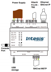
ELECTRICAL & MECHANICAL FEATURES
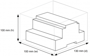
| Enclosure | Plastic, type PC (UL 94 V-0)Net dimensions (dxwxh): 90x88x56 mmRecommended space for installation (dxwxh): 130x100x100mmColor: Light Grey. RAL 7035 |
| Mounting | Wall.DIN rail EN60715 TH35 |
| Terminal Wiring (for power supply and low-voltage signals) | Per terminal: solid wires or stranded wires (twisted or with ferrule)1 core: 0.5mm2…2.5mm2 2 cores: 0.5mm2… 1.5mm23 cores: not permittedIf cables are more than 3.05 meters long, Class 2 cable is required |
| Power | 1 x Plug-in screw terminal block (3 poles)9 to 36VDC +/-10%, Max.: 140mA.24VAC +/-10% 50-60Hz, Max.: 127mARecommended: 24VDC |
| Ethernet | 1 x Ethernet 10/100 Mbps RJ452 x Ethernet LED: port link and activity |
| Port A | 1 x H-Link Plug-in screw terminal block orange (2 poles)1500VDC isolation from other ports1 x Plug-in screw terminal block green (2 poles)Reserved for future use |
| Switch A (SWA) | 1 x DIP-Switch for PORT A configuration:Reserved for future use |
| PORT B | 1 x Serial EIA232 (SUB-D9 male connector)Reserved for future use1 x Serial EIA485 Plug-in screw terminal block (3 poles)A, B, SGND (Reference ground or shield)1500VDC isolation from other ports (except PORT B: EIA232) |
| Switch B (SWB) | 1 x DIP-Switch for serial EIA485 configuration:Position 1:ON: 120 Ω termination activeOff: 120 Ω termination inactivePosition 2-3:ON: Polarization activeOff: Polarization inactive |
| Battery | Size: Coin 20mm x 3.2mmCapacity: 3V / 225mAhType: Manganese Dioxide Lithium |
| Console Port | Mini Type-B USB 2.0 compliant 1500VDC isolation |
| USB port | Type-A USB 2.0 compliantOnly for USB flash storage device (USB pen drive)Power consumption limited to 150mA (HDD connection not allowed) |
| Push Button | Button A: Check the user manualButton B: Check the user manual |
| Operation Temperature | 0°C to +60°C |
| Operational Humidity | 5 to 95%, no condensation |
| LED Indicators | 10 x Onboard LED indicators2 x Run (Power)/Error2 x Ethernet Link/Speed2 x Port A TX/RX2 x Port B TX/RX1 x Button A indicator1 x Button B indicator |
![]() This marking on the product, accessories, packaging or literature (manual) indicates that the product contains electronic parts and they must be properly disposed of by following the instructions at https://intesis.com/weee-regulation
This marking on the product, accessories, packaging or literature (manual) indicates that the product contains electronic parts and they must be properly disposed of by following the instructions at https://intesis.com/weee-regulation

References
[xyz-ips snippet=”download-snippet”]