Intesis Interface integration Haier air conditioners User Manual KNX TP1 (EIB)
|
ORDER CODE |
LEGACY ORDER CODE |
|
INKNXHAI008C000 |
HA-AC-KNX-8 |
|
INKNXHAI016C000 |
HA-AC-KNX-16 |
| INKNXHAI064C000 |
HA-AC-KNX-64 |
Important User Information
Disclaimer
The information in this document is for informational purposes only. Please inform HMS Industrial Networks of any inaccuracies or omissions found in this document. HMS Industrial Networks disclaims any responsibility or liability for any errors that may appear in this document.
HMS Industrial Networks reserves the right to modify its products in line with its policy of continuous product development. The information in this document shall therefore not be construed as a commitment on the part of HMS Industrial Networks and is subject to change without notice. HMS Industrial Networks makes no commitment to update or keep current the information in this document.
The data, examples and illustrations found in this document are included for illustrative purposes and are onlyintended to help improve understanding of the functionality and handling of the product. In view of the wide range of possible applications of the product, and because of the many variables and requirements associated with any particular implementation, HMS Industrial Networks cannot assume responsibility or liability for actual use based on the data, examples or illustrations included in this document nor for any damages incurred during installation of the product. Those responsible for the use of the product must acquire sufficient knowledge in order to ensure that the product is used correctly in their specific application and that the application meets all performance and safety requirements including any applicable laws, regulations, codes and standards. Further, HMS Industrial Networks will under no circumstances assume liability or responsibility for any problems that may arise as a result from the use of undocumented features or functional side effects found outside the documented scope of the product. The effects caused by any direct or indirect use of such aspects of the product are undefined and may include e.g. compatibility issues and stability issues.
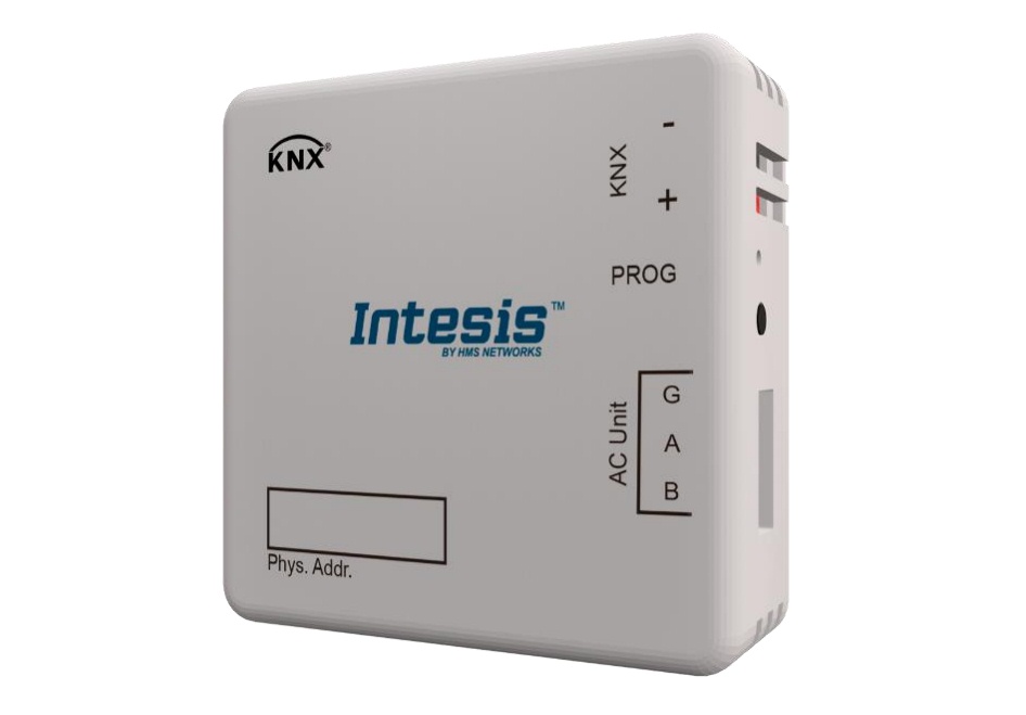
1 Presentation
 INKNXHAI0–C000allows a complete and natural integration of Haier air conditioners with KNX control systems.Compatible with all models of VRF line of Haier air conditioners.
Main features:
- Reduced dimensions. Installation even inside the A.C. indoor unit.
- Quick and non-visible installation.
- External power not required.
- Direct connection to the KNX EIB bus.
- Direct connection to the AC indoor unit.
- Fully KNX interoperable, configuration from ETS.
- Multiple objects for control (of different types: bit, byte, characters…).
- Control of the AC unit based in the ambient temperature read by the own AC unit, or in the ambient temperature read by any KNX thermostat.
- Total Control and Monitoring of the AC unit from KNX, including monitoring of AC unit’s state of internal variables, running hours counter (for filter maintenance control), and error indication and error code.
- AC unit can be controlled simultaneously by the IR remote control of the AC unit and by KNX.
2 Connection
Connection of the interface to the AC indoor unit:
Disconnect mains power from the AC unit. Open the front cover of the indoor unit in order to have access to the internal control board. In the control board locate the socket connector marked as ABG1.
Using a 3-wire cable, connect the ABG1 connector from the INKNXHAI0- C000to the A B G1 connector of the AC unit’s control board.
Fix the INKNXHAI0–C000inside or outside the AC indoor unit depending on your needs – remember that INKNXHAI0–C000must be also connected to the KNX bus. Close the AC indoor unit’s front cover again.
Connection of the interface to the KNX bus:
Disconnect power of the KNX bus. Connect the interface to the KNX TP-1 (EIB) bus using the KNX standard connector (red/grey) of the interface, respect polarity. Reconnect power of the KNX bus.
Connections diagram:
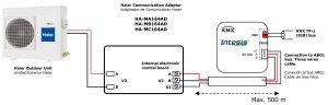 Figure 2.1 Default parameter configuration
Each Haier Communication Adaptor connects to a single Outdoor Unit.
The INKNXHAI008C000-16-64 can be connected to more than one Haier Communication Adaptor simultaneously.
NOTE: More than one Haier Communication Adaptor can be present in the installation.Please make sure that the address of the Haier Communication Adaptor is correctly set in the ETS. Check section 4.6 for more information.
3 Configuration and setup
This is a fully compatible KNX device which must be configured and setup using standard KNX tool ETS.
ETS project for this device can be downloaded from: https://www.intesis.com/products/ac-interfaces/haier-gateways/haier-knx-vrf-ha-ac-knx
Please consult the README.txt file, located inside the downloaded zip file, to find instructions on how to install the database.
4 ETS Parameters
When imported to the ETS software for the first time, the gateway shows the following default parameter configuration: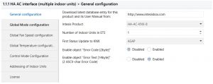 Figure 4.1 Default parameter configuration
With this configuration it’s possible to send On/Off (Control_ On/Off), change the AC Mode (Control_ Mode), the Fan Speed (Control_ Fan Speed) and also the Setpoint Temperature (Control_ Setpoint Temperature). The Status_ objects, for the mentioned Control_ objects, are also available to use if needed. Objects Status_ AC Ambient Reference Temperature and Status_ Error/Alarm are shown too.
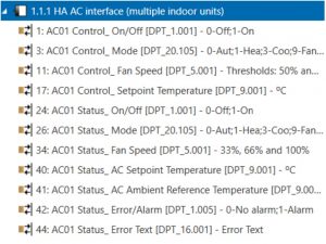 Figure 4.2 Default communication objects
4.1 General configuration
Inside this parameter’s dialog it is possible to activate or change the parameters shown in the Figure 4.1.
4.1.1 Download latest database entry for this product and its User Manual from:The first field shows the URL where to download the database and the user manual for the product.![]() Figure 4.3 Parameter detail
Figure 4.3 Parameter detail
4.1.2 Intesis ProductThis parameter is used to check, before sending the programing, the maximum number of AC units your device supports.![]() Figure 4.4 Parameter detail
Figure 4.4 Parameter detail
Select the version of the gateway that you have:
- INKNXHAI008C000, if you only want to control up to 8 AC unit.
- INKNXHAI016C000, if you only want to control up to 16 AC units.
- INKNXHAI064C000, if you only want to control up to 64 AC units.
4.1.3 Number of Indoor Units in ETSThis parameter is used to hide/show communication object according to the number of AC units you need to configure. Value ranges go from 1 to 64.![]() Figure 4.5 Parameter detail
Figure 4.5 Parameter detail
In case you introduce a number higher than the maximum number of units allowed by your license, you will get a warning message. This is just for information and will not block the configuration process. Configurations with more indoor units configured than the ones allowed by the license will not be downloaded correctly.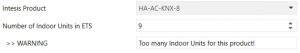 Figure 4.6 Parameter detail
4.1.4 First Status Updated to KNXThis parameter defines how fast the status is updated to KNX. Depending on the value selected, more or less priority will be assigned to this action. As there are so many parameters available, it is important to consider carefully how to set this parameter.
- If set to “ASAP”, all status communication objects will send its value (if needed).
- If set to “Slow”, all status communication objects will send its value (if needed), but slower than in the previous option (ASAP).
- If set to “Super Slow”, all status communication objects will send its value (if needed), but slower than in the previous option (Slow).
 Figure 4.7 Parameter detail
4.1.5 Enable object “Error Code [2byte]”This parameter shows/hides the Status_ Error Code communication object which shows the indoor unit errors, if occurred, in numeric format.
 Figure 4.8 Communication object and parameter detail
- If set to “Disabled” the object will not be shown.
- If set to “Enabled” the Status_ Error Code [2byte signed value] object will appear.
- This object can be read and also sends the indoor unit error, if occurred, in numeric format. If a “0” value is shown that means no error.
4.1.6 Enable object “Error Text Code [14byte]”This parameter shows/hides the Status_ Error Text Code communication object which shows the indoor unit errors, if occurred, in text format.
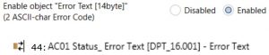 Figure 4.9 Communication object and parameter detail
- If set to “Disabled” the object will not be shown.
- If set to “Enabled” the Status_ Error Text Code object will appear.
- This object can be read and also sends the indoor unit error, if occurred, in text format. The errors shown have the same format as in the remote controller and in the error list from the indoor unit manufacturer. If the object’s value is empty, that means there is no error.
4.2 Global mode configuration
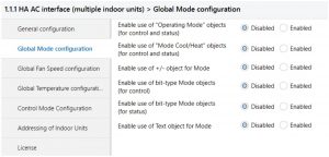 Figure 4.10 Default Mode Configuration dialog
All the parameters in this section are related with the different mode properties and communication objects.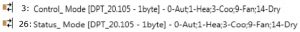
The byte-type communication object for Mode works with the DTP_20.105. Auto mode will be enabled with a “0” value, Heat mode with a “1” value, Cool mode with a “3” value, Fan mode with a “9” value and Dry mode with a “14” value.
4.2.1 Enable use of “Operating Mode” objectsThis parameter shows/hides the Control_ and Status_ Mode Operating Mode communication objects.
4.2.2 Enable use of Mode Heat/Cool objects
This parameter shows/hides the Control_ and Status_ Mode Cool/Heat communication objects.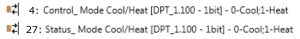
- If set to “Disabled” the objects will not be shown.
- If set to “Enabled” the Control_ and Status_ Mode Cool/Heat objects will appear.
- When a “1” value is sent to the Control_ communication object, Heat mode will be enabled in the indoor unit, and the Status_ object will return this value.
- When a “0” value is sent to the Control_ communication object, Cool mode will be enabled in the indoor unit, and the Status_ object will return this value.
4.2.3 Enable use of + / – object for Mode
This parameter shows/hides the Control_ Mode +/- communication object which let’s you change the indoor unit mode by using two different datapoint types.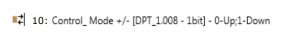
- If set to “Disabled” the object will not be shown.
- If set to “Enabled” the Control_ Mode +/- object and a new parameter will appear. Figure 4.11 Parameter detail
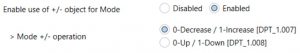 Figure 4.11 Parameter detail
 ➢ DPT type for +/- Mode Object
This parameter lets choose between the datapoints 0-Up / 1-Down [DPT_1.008] and 0-Decrease / 1-Increase [DPT_1.007] for the Control_ Mode +/- object.
The sequence followed when using this object is shown below:
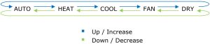
Keep in mind that depending on the indoor unit you have and the available features, Auto mode and Dry mode may not be present.
4.2.4 Enable use of bit-type Mode objects (for control)
This parameter shows/hides the bit-type Control_Mode objects.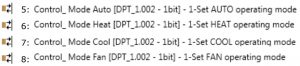
![]()
- If set to “no” the objects will not be shown.
- If set to “yes” the Control_ Mode objects for Auto, Heat, Cool, Fan and Dry will appear. To activate a mode by using these objects a “1” value has to be sent.
4.2.5 Enable use of bit-type Mode objects (for status)
This parameter shows/hides the bit-type Status_ Mode objects.
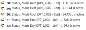
- If set to “no” the objects will not be shown.
- If set to “yes” the Status_ Mode objects for Auto, Heat, Cool, Fan and Dry will appear.When enabled, a mode will return a “1” through its bit-type object.
4.2.6 Enable use of Text object for Mode
This parameter shows/hides the Status_ Mode Text communication object.![]()
- If set to “no” the object will not be shown.
- If set to “yes” the Status_ Mode Text object will appear. Also, in the parameters, will be shown five text fields, one for each mode, that will let modify the text string displayed by the Status_ Mode Text when changing mode.
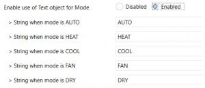 Figure 4.12 Parameter detail
4.3 Global Fan Speed Configuration dialog
 Figure 4.13 Default Fan Speed Configuration dialog
All the parameters in this section are related with the Fan Speed properties and communication objects.
4.3.1 DPT object type for fan speed
With this parameter is possible to change de DPT for the Control_ Fan Speed and Status_ Fan Speed byte-type communication objects. Datapoints Scaling (DPT_5.001) and Enumerated (DPT_5.010) can be selected.
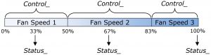
- When “Enumerated [DPT 5.010]” is selected, Control_ Fan Speed and Status_ Fan Speed communication objects for this DPT will appear. Also, depending on the number of fan speeds selected, these objects will be different.The first fan speed will be selected if a “1” is sent to the Control_ object. The secondone will be selected sending a “2”, and the last one sending a “3”.The Status_ object will always return the value for the fan speed selected. Important: If a “0” value is sent to the Control_ object, the minimum fan speed will be selected. If a value bigger than “3” is sent to the Control_ object, then the maximum fan speed will be selected.
- When “Scaling [DPT 5.001]” is selected, Control_ Fan Speed and Status_Fan Speed communication objects for this DPT will appear. Also, depending on the number of fan speeds selected, these objects will be different.
 The first fan speed will be selected if a “1” is sent to the Control_ object. The secondone will be selected sending a “2”, and the last one sending a “3”.The Status_ object will always return the value for the fan speed selected.
When a value between 0% and 49% is sent to the Control_ object the first fan speed will be selected.When a value between 50% and 83% is sent to the Control_ object, the second speed will be selected.When a value between 84% and 100% is sent to the Control_ object, the third speed will be selected.The Status_ object will return a 33% when the first speed is selected, a 67% for the second one and a 100% for the third one.
4.3.2 Enable use of “Fan Speed Man/Auto” objects (for Control and Status)This parameter shows/hides the Control_ Fan Speed Man/Auto and Status_ Fan Speed Man/Auto communication object which lets you set the Fan Speed into Manual or Auto mode.
4.3.3 Enable use of +/- object for Fan Speed
This parameter shows/hides the Control_ Fan Speed +/- communication object which lets you increase/decrease the indoor unit fan speed by using two different datapoint types.![]()
- If set to “no” the object will not be shown.
- If set to “yes” the Control_ Fan Speed +/- object and a new parameter will appear.
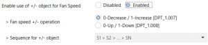
➢ Fan speed +/- operationThis parameter lets choose between the datapoints 0-Up / 1-Down [DPT_1.008] and 0-Decrease / 1-Increase [DPT_1.007] for the Control_ Fan Speed +/- object.
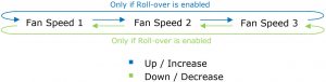
➢ Sequence for +/- objectThis parameter lets choose between the different modes available:
- S1>S2>….>SNSelect this option if you don’t have Auto mode and you don’t want roll-over to be enabled.
- S1>S2>….>SN>S1>…Select this option if you don’t have Auto mode and you want roll-over to be enabled.
- Auto>S1>S2>….>SNSelect this option if you have Auto mode and you don’t want roll-over to be enabled.
- Auto>S1>S2>….>SN>Auto>S1>…Select this option if you have Auto mode and you want roll-over to be enabled.
4.3.4 Enable use of bit-type Fan Speed objects (for Control)This parameter shows/hides the bit-type Control_ Fan Speed objects.
- If set to “no” the objects will not be shown.
- If set to “yes” the Control_ Fan Speed objects for Speed 1, Speed 2 and Speed 3 (if available) will appear. To activate a Fan Speed by using these objects a “1” value has to be sent.
4.3.5 Enable use of bit-type Fan Speed objects (for Status)
This parameter shows/hides the bit-type Status_ Fan Speed objects.
- If set to “no” the objects will not be shown.
- If set to “yes” the Status_ Fan Speed objects for Speed 1, Speed 2 and Speed 3 (if available) will appear. When a Fan Speed is enabled, a “1” value is returned through its bittype object.
4.3.6 Enable use of Text object for Fan Speed
This parameter shows/hides the Status_ Fan Speed Text communication object.![]()
- If set to “no” the object will not be shown.
- If set to “yes” the Status_ Fan Speed Text object will appear. Also, in the parameters, will be shown two (or three, depending on the number of fan speeds selected) text fields, one for each Fan Speed, that will let modify the text string displayed by the Status_Fan Speed Text when changing a fan speed.Figure 4.15 Parameter detail
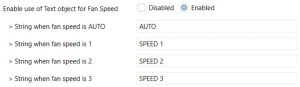 Figure 4.15 Parameter detail
4.4 Global temperature configuration
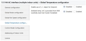 Figure 4.20 Default Temperature Configuration dialog
All the parameters in this section are related with the Temperature properties and communication objects.
4.4.1 Enable use of +/- obj for Setpoint
This parameter shows/hides the Control_ Setpoint Temp +/- communication object which lets you change the indoor unit setpoint temperature by using two different datapoint types.![]()
- If set to “no” the object will not be shown.
- If set to “yes” the Control_ Setpoint Temp +/- object and a new parameter will appear.
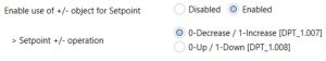 Figure 4.23 Parameter detail
➢ DPT type for +/- Setp Temp objectThis parameter lets choose between the datapoints 0-Up / 1-Down [DPT_1.008] and 0-Decrease / 1-Increase [DPT_1.007] for the Control_ Setpoint Temp +/- object.(Lower limit) 16ºC ![]() 17ºC
17ºC ![]() …
… ![]() 31ºC
31ºC ![]() 32ºC (Upper limit)
32ºC (Upper limit)![]() Up / Increase
Up / Increase![]() Down / Decrease
Down / Decrease
4.4.2 Ambient Ref. Temp. is provided from KNX
This parameter shows/hides the Control_ Ambient Temperature communication object which lets you use an ambient temperature reference provided by a KNX device.![]()
- If set to “no” the object will not be shown.
- If set to “yes” the Control_ Ambient Temperature object will appear. Meant to be enabled when you want the temperature provided by a KNX sensor to be the reference ambient temperature for the air conditioner. Then, the following formula applies for the calculation of real Control_ Setpoint Temperature sent ot the AC unit:“AC Setp. Temp” = “Ambient ref. Temp” – (“KNX Amb. Temp.” – “KNX Setp Temp.”) Temp”)
- AC Setp. Temp: AC indoor unit setpoint temperature
- Ambient Ref. Temp: AC indoor unit return temperature
- KNX Amb. Temp.: Ambient temperature provided from KNX
- KNX Setp. Temp: Setpoint temperature provided from KNXAs an example, consider the following situation:User wants: 19ºC (“KNX Setp. Temp.”)User sensor (a KNX sensor) reads: 21ºC (“KNX Amb Temp.”)Ambient temp. read by Haier system is: 24ºC (“Ambient Ref. Temp”)In this example, the final setpoint temperature that INKNXHAI0–C000will send out to the indoor unit (shown in “Setp. Temp.”) will become 24ºC – (21ºC – 19ºC) = 22ºC. This is the setpoint that will actually be requested to Haier unit.This formula will be applied as soon as the Control_ Setpoint Temperature and Control_ Ambient Temperature objects are written at least once from the KNX installation. After that, they are kept always consistent.Note that this formula will always drive the AC indoor unit demand in the right direction, regardless of the operation mode (Heat, Cool or Auto).
4.5 Control Mode configuration
 Figure 4.20 Control Mode Configuration dialog
All the parameters in this section are related with the Mode properties and communication objects.
4.5.1 Enable use of Control Mode objects (for Control and Status)
This parameter shows/hides the Control_ Control Mode and Status_ Control Mode communication objects which lets you change the indoor unit control: No Central, LIFO (Last Input First Output), Central Controller and Lock Central Controller.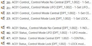
- If set to “no” the objects will not be shown.
- If set to “yes” the Control_ and Status_ Control Mode objects for No Central, LIFO (Last Input First Output), Central Controller, Lock Central Controller will appear.
4.5.1 Initial state of Control Mode
This parameter sets the initial value for the Control Mode: No Central, LIFO (Last Input First Output), Central Controller, Lock Central Controller or Do not initialize.
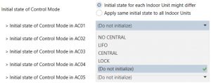 Figure 4.24 Parameter detail
- If set to “Apply same initial state to all Indoor Units”, the parameter option selected will apply to all indoor units.
- If set to “Initial state for each Indoor Unit might differ”, you will be able to set this parameter for each Indoor Unit individually.
4.6 Addressing of Indoor Units
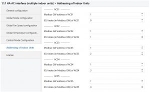 Figure 4.24 Parameter detail
In this section you will be able to set the AC addressing for each AC unit present in the installation.
- Modbus GW address of ACxx refers to the addres of the Haier Communication Addapters.
- IDU index (in Modbus GW) of ACxx refers to the AC system address of the Indoor Unit.
4.7 License
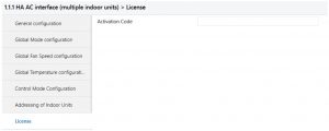 Figure 4.24 Parameter detail
Use this section to introduce the migration code in case you need to update your box from another version different from the factory default one.
5 Technical Specifications
|
Enclosure |
ABS (UL 94 V-0) de 2,5 mm / 1” thick Net dimensions (dxwxh): 71 x 71 x 27 mm / 2.8” x 2.8” x 1.1” Color: White RAL 9010 |
Operation Temperature |
0ºC to +60ºC |
|
Weight |
42 g. |
Stock Temperature |
-20ºC to +85ºC |
|
Power supply |
Power is supplied by: 1 x KNX bus (29V DC, 7mA) |
Operational Humidity |
<90% RH, non-condensing |
|
Terminal Wiring (for low-voltage signals) |
For terminal: solid wires or stranded wires (twisted or with ferrule) 1 core: 0.5mm2… 2.5mm2 2 cores: 0.5mm2… 1.5mm2 3 cores: not permitted |
Stock Humidity |
<90% RH, non-condensing |
|
KNX port |
1 x KNX TP1 (EIB) port opto-isolated. Plug-in terminal block (2 poles). TNV-1 |
Isolation voltage |
1500 VDC |
|
AC unit port |
1 x Specific connector Plug-in terminal block (3 poles) |
Isolation resistance |
1000 MΩ |
|
Configuration |
Configuration with ETS |
Protection |
IP20 (IEC60529) |
|
LED indicators |
1 x Onboard LED – Operational status |

6 AC Unit Types compatibility.
A list of Haier indoor unit model references compatible with INKNXHAI0- C000and their available features can be found in: [PDF]
7 Error Codes
|
Error Code in KNX Object |
Error in Remote Controller |
Category |
Error Name |
|
1 |
1 |
Indoor Unit |
Indoor ambient temp.sensor TA (Tas) failure |
|
2 |
2 |
Indoor gas pipe temp. sensor TC1 failure | |
|
3 |
3 |
Indoor liquid pipe temp. sensor TC2 failure | |
|
4 |
4 |
Dual heat source sensor TW failure | |
|
5 |
5 |
Indoor EEPROM failure | |
|
6 |
6 |
Communication between indoor and outdoor failure | |
|
7 |
7 |
Communication between indoor and wired controller failure | |
|
8 |
8 |
Indoor float switch failure |
|
|
9 |
9 |
Indoor address repeated failure | |
|
10 |
10 |
Reserved | |
|
11 |
11 |
Reserved |
|
|
12 |
12 |
No 50 Hz zero passage signal | |
|
13 |
13 |
Coil sensor TC3 failure | |
|
14 |
14 |
DC motor failure | |
|
15 |
15 |
Indoor ambient temp.sensor TA (Taf) failure | |
|
16 |
16 |
– | |
|
17 |
17 |
Outdoor Unit |
– |
|
18 |
18 |
– | |
|
19 |
19 |
– | |
|
20 |
20 |
Defrosting temp. sensor Tdef1 failure Defrosting temp. sensor Tdef2 failure | |
|
21 |
21 |
Ambient temp. sensor Ta failure | |
|
22 |
22 |
Suction temp. sensor Ts1 failure Suction temp. sensor Ts2 failure Suction temp. sensor Tsacc failure Suction temp. sensor Tsuc failure | |
|
23 |
23 |
Discharging temp. sensor Tdi failure Discharging temp. sensor Td1 failure Discharging temp. sensor Td2 failure | |
|
24 |
24 |
Oil temp. sensor Toilp failure Oil temp. sensor Toil failure | |
|
25 |
25 |
Inlet temp. of heat exchanger Toci1 failure Inlet temp. of heat exchanger Toci2 failure | |
|
26 |
26 |
indoor communication failure
Reduce the number of indoor units failure Increase the number of indoor units failure |
|
|
27 |
27 |
Oil temp. too high protection (Toil) Oil temp. too high protection (Toi2) | |
|
28 |
28 |
High pressure sensor Pd1 failure High pressure sensor Pd2 failure | |
|
29 |
29 |
Low pressure sensor Ps failure | |
|
30 |
30 |
High pressure switch HPSi failure High pressure switch HPS1 failure High pressure switch HPS2 failure | |
|
31 |
31 |
Liquid pipe pressure Pl failure | |
|
32 |
32 |
Outlet temp. of subcooler Tsco failure
Liquid pipe SC temp. of subcooler Tliqsc failure |
|
|
33 |
33 |
EEPROM (AT24C04) failure | |
|
34 |
34 |
Discharging temp. too high protection (Tdi) Discharging temp. too high protection (Td1) Discharging temp. too high protection (Td2) | |
|
35 |
35 |
4-way valve reversing failure 4-way valve reversing failure | |
|
36 |
36 |
Oil temp. too low protection (Toil) Oil temp. too low protection (Toi2) | |
|
37 |
37 |
Lack of phase of 3N power supply or wrong phase sequence | |
|
38 |
38 |
High pressure sensor Pd too low protection | |
|
39 |
39 |
Low pressure sensor Ps too low protection Compression ratio too high protection
Compression 1 ratio too low protection Compression 2 ratio too low protection |
|
|
40 |
40 |
High pressure sensor Pd1 too high protection High pressure sensor Pd2 too high protection | |
|
41 |
41 | Water temp. Twi too low protection Water temp. Twi too high protection | |
|
42 |
42 |
Frost protection of water system
Water system out of water freeze protection Water flow of Water system is too small to protect |
|
|
43 |
43 |
Discharging temp. sensor Tdi too low protection Discharging temp. sensor Td1 too low protection Discharging temp. sensor Td2 too low protection |
|
44 |
44 |
Low pressure sensor PS too high protection |
|
45 |
45 |
Communication among outdoors failure |
|
46 |
46 |
Communication with inverter board 1 failure Communication with inverter board 2failure |
|
47 |
47 |
– |
|
48 |
48 |
Unloading valve SV1 failure |
|
49 |
49 |
– |
|
50 |
50 |
|
|
51 |
51 |
– |
|
52 |
52 |
– |
|
53 |
53 |
Current detector CT1 failure |
|
54 |
54 |
Communication with Thermal storage module failure |
|
55 |
55 |
Thermal storage module LEV failure |
|
56 |
56 |
Thermal storage module too hot failure |
|
57 |
57 |
Communication between Thermal storage module and host computer |
|
58 |
58 |
Thermal storage module Tc1 temp. sensor failure |
|
59 |
59 |
Thermal storage module Tc2 temp. sensor failure |
|
60 |
60 |
Reserved |
|
61 |
61 |
Reserved |
|
62 |
62 |
Reserved |
|
63 |
63 |
Thermal storage module DIP setting failure |
|
64 |
64 |
CT1 over current CT2 over current |
|
65 |
65 |
– |
|
66 |
66 |
– |
|
67 |
67 |
Communication with motor driving board failure |
|
68 |
68 |
– |
|
69 |
69 |
– |
|
70 |
70 |
– |
|
71 |
71 |
Left DC motor blocked Right DC motor blocked |
|
72 |
72 |
Left DC motor reversed Right DC motor reversed |
|
73 |
73 |
Left DC motor current too high Right DC motor current too high |
|
74 |
74 |
– |
|
75 |
75 |
No pressure drop between high pressure and low one Pressure too low between high pressure and low one |
|
76 |
76 |
Incorrect outdoor address or capacity setting |
|
77 |
77 |
Oil equalization protection among outdoors |
|
78 |
78 |
Lack of refrigerant in cooling Lack of refrigerant in heating |
|
79 |
79 |
Incorrect wiring |
|
80 |
80 |
Indoor and outdoor do not match |
|
81 |
81 |
Model temp. too high protection |
|
82 |
82 |
Compressor current protection |
|
83 |
83 |
Wrong model selection |
|
84 |
84 |
– |
|
85 |
85 |
– |
|
86 |
86 |
– |
|
87 |
87 |
– |
|
88 |
88 |
– |
|
89 |
89 |
– |
|
90 |
90 |
– |
|
91 |
91 |
– |
|
92 |
92 |
– |
|
93 |
93 |
– |
|
94 |
94 |
– |
|
95 |
95 |
– |
|
96 |
96 |
– |
|
97 |
97 |
– |
|
98 |
98 |
– |
|
99 |
99 |
Program self-test failure |
|
100 |
100 |
DC motor driving board IPM alarm |
|
101 |
101 |
DC motor driving board detecting out of control |
|
102 |
102 |
DC motor driving board EEPROM faulty |
|
103 |
103 |
DC motor driving board over current or current detector damaged |
|
104 |
104 |
Voltage too low protection of DC motor driving board |
|
105 |
105 |
Voltage too high protection of DC motor driving board |
|
106 |
106 |
DC motor driving board blocked |
|
107 |
107 |
Protection of motor rate over Limitation |
|
108 |
108 |
– |
|
109 |
109 |
– |
|
110 |
110 |
model 1 Over current model 2 Over current |
|
111 |
111 |
Compressor 1 out of control Compressor 2 out of control | |
|
112 |
112 |
Radiator of model 1 temp. too high Radiator of model 2 temp. too high | |
|
113 |
113 |
model 1 overload
model 2 overload |
|
|
114 |
114 |
Voltage too low of model 1 Voltage too low of model 2 |
|
|
115 |
115 |
Voltage too high of model 1 Voltage too high of model 2 | |
|
116 |
116 |
Communication abnormal with model 1 Communication abnormal with model 2 | |
|
117 |
117 |
Model 1 Over current (software) Model 1 Over current (software) | |
|
118 |
118 |
Model 1 startup failure Model 2 startup failure | |
|
119 |
119 |
Current Detecting Circuit Abnormal of transducer 1 Current Detecting Circuit Abnormal of transducer 2 | |
|
120 |
120 |
Power supply of transducer 1 abnormal Power supply of transducer 2 abnormal | |
|
121 |
121 |
Power supply of inverter board 1 is abnormal Power supply of inverter board 2 is abnormal | |
|
122 |
122 |
Radiator temp. sensor of transducer 1 abnormal Radiator temp. sensor of transducer 2 abnormal | |
|
123 |
123 |
– | |
|
124 |
124 |
– | |
|
125 |
125 |
Compressor 1 frequency not match Compressor 2 frequency not match | |
|
126 |
126 |
– | |
|
127 |
127 |
MCU reset abnormal | |
|
128 |
128 |
MCU Program needs to be upgraded | |
|
0 |
N/A |
KNX interface | No error |
|
65535 (-1) |
N/A |
KNX interface | Indoor Units not ready for communication |
|
65436 (-100) |
N/A |
KNX interface | License Error / indoor unit not supported by current license |
|
65336 (-200) |
N/A |
KNX interface | Overconsumption error in EXY bus |
In case you detect an error code not listed, contact your nearest Haier technical support service for more information on the error meaning.
Appendix A – Communication Objects Table
|
SECTION |
OBJECT NUMBER |
NAME |
LENGTH |
DATAPOINT TYPE | FLAGS |
FUNCTION |
||
| DPT_NAME | DPT_ID | R | W | T | U | |||
| On/Off | 1 | Control_ On/Off | 1 bit | DPT_Switch | 1.001 | W | T | 0 – Off; 1-On |
|
Mode |
2 | Control_ Operating Mode | 1 byte | DPT_HVACMode | 20.102 | W | T | 0 – Auto; 1 – Com; 2 – Stan; 3 – Eco; 4 – Pro |
| 3 | Control_ Mode | 1 byte | DPT_HVACControl | 20.105 | W | T | 0 – Auto; 1 – Heat; 3 – Cool; 9 – Fan; 14 – Dry | |
| 4 | Control_ Mode Cool/Heat | 1 bit | DPT_Cool/Heat | 1.100 | W | T | 0 – Cool; 1 – Heat | |
| 5 | Control_ Mode Auto | 1 byte | DPT_Scaling | 5.001 | W | T | 1 – Auto | |
| 6 | Control_ Mode Heat | 1 byte | DPT_Scaling | 5.001 | W | T | 1 – Heat | |
| 7 | Control_ Mode Cool | 1 bit | DPT_Bool | 1.002 | W | T | 1 – Cool | |
| 8 | Control_ Mode Fan | 1 bit | DPT_Bool | 1.002 | W | T | 1 – Dry | |
| 9 | Control_ Mode Dry | 1 bit | DPT_Bool | 1.002 | W | T | 1 – Fan | |
|
10 |
Control_ Mode +/- | 1 bit | DPT_Step | 1.007 | W | 0 – Decrease; 1 – Increase | ||
| Control_ Mode +/- | 1 bit | DPT_UpDown | 1.008 | W | 0 – Up; 1 – Down | |||
|
Fan Speed |
11 |
Control_ Fan Speed / 3 Speeds |
1 byte |
DPT_Scaling |
5.001 |
W |
T |
0%-49% – Speed 1; 50%-83% – Speed 2;
84%-100% Speed 3 |
| Control_ Fan Speed / 3 Speeds | 1 byte | DPT_Enumerated | 5.010 | W | T | 1 – Speed 1; 2 – Speed 2; 3 Speed 3 | ||
| 12 | Control_ Fan Speed Man/Auto | 1 bit | DPT_Bool | 1.002 | W | T | 0 – Manual; 1 – Auto | |
| 13 | Control_ Fan Speed 1 | 1 bit | DPT_Bool | 1.002 | W | T | 1 – Fan Speed 1 | |
| 14 | Control_ Fan Speed 2 | 1 bit | DPT_Bool | 1.002 | W | T | 1 – Fan Speed 2 | |
| 15 | Control_ Fan Speed 3 | 1 bit | DPT_Bool | 1.002 | W | T | 1 – Fan Speed 3 | |
|
16 |
Control_ Fan Speed +/- | 1 bit | DPT_Step | 1.007 | W | T | 0 – Decrease; 1 – Increase | |
| Control_ Fan Speed +/- | 1 bit | DPT_UpDown | 1.008 | W | T | 0 – Up; 1 – Down |
|
Temperature |
17 | Control_ Setpoint Temperature | 2 byte | DPT_Value_Temp | 9.001 | W | T | 17ºC to 30ºC |
|
18 |
Control_ Setpoint Temp +/- | 1 bit | DPT_Step | 1.007 | W | 0 – Decrease; 1 – Increase | ||
| Control_ Setpoint Temp +/- | 1 bit | DPT_UpDown | 1.008 | W | 0 – Up; 1 – Down | |||
| 19 | Control_ Ambient Temperature | 2 byte | DPT_Value_Temp | 9.001 | W | T | ºC value in EIS5 format | |
|
Control Mode |
20 | Control_ Control Mode No Central | 1 bit | DPT_Bool | 1.002 | W | T | 1 – No Central Controller |
| 21 | Control_ Control Mode LIFO | 1 bit | DPT_Bool | 1.002 | W | T | 1 – Last Input First Output (LIFO) | |
| 22 | Control_ Control Mode Central | 1 bit | DPT_Bool | 1.002 | W | T | 1 – Central Controller | |
| 23 | Control_ Control Mode Lock | 1 bit | DPT_Bool | 1.002 | W | T | 1 – Lock Central Controller |
| On/Off | 24 | Status_ On/Off | 1 bit | DPT_Switch | 1.001 | R | T | 0 – Off; 1-On |
|
Mode |
25 | Status_ Operating Mode | 1 byte | DPT_HVACMode | 20.102 | R | T | 0 – Auto; 1 – Com; 2 – Stan; 3 – Eco; 4 – Pro |
| 26 | Status_ Mode | 1 byte | DPT_HVACContrMode | 20.105 | R | T | 0 – Auto; 1 – Heat; 3 – Cool; 9 – Fan; 14 – Dry | |
| 27 | Status_ Mode Cool/Heat | 1 bit | DPT_Heat/Cool | 1.100 | R | T | 0 – Cool; 1 – Heat | |
| 28 | Status_ Mode Auto | 1 bit | DPT_Bool | 1.002 | R | T | 1 – Auto | |
| 29 | Status_ Mode Heat | 1 bit | DPT_Bool | 1.002 | R | T | 1 – Heat | |
| 30 | Status_ Mode Cool | 1 bit | DPT_Bool | 1.002 | R | T | 1 – Cool | |
| 31 | Status_ Mode Fan | 1 bit | DPT_Bool | 1.002 | R | T | 1 – Fan | |
| 32 | Status_ Mode Dry | 1 bit | DPT_Bool | 1.002 | R | T | 1 – Dry | |
| 33 | Status_ Mode Text | 14 byte | DPT_String_8859_1 | 16.001 | R | T | ASCII String | |
|
Fan Speed |
34 |
Status_ Fan Speed / 3 Speeds | 1 byte | DPT_Scaling | 5.001 | R | T | 33% – Speed 1; 67% – Speed 2; 100% – Speed 3 |
| Status_ Fan Speed / 3 Speeds | 1 byte | DPT_Enumerated | 5.010 | R | T | 1 – Speed 1; 2 – Speed 2; 3 – Speed 3 | ||
| 35 | Status_ Fan Speed Man/Auto | 1 bit | DPT_Bool | 1.002 | R | T | 0 – Manual; 1 – Auto |
| 36 | Status_ Fan Speed 1 | 1 bit | DPT_Bool | 1.002 | R | T | 1 – Speed 1 | |
| 37 | Status_ Fan Speed 2 | 1 bit | DPT_Bool | 1.002 | R | T | 1 – Speed 2 | |
| 38 | Status_ Fan Speed 3 | 1 bit | DPT_Bool | 1.002 | R | T | 1 – Speed 3 | |
| 39 | Status_ Fan Speed Text | 14 byte | DPT_String_8859_1 | 16.001 | R | T | ASCII String | |
|
Temperature |
40 | Status_ AC Setpoint Temp | 2 byte | DPT_Value_Temp | 9.001 | R | T | 16ºC to 32ºC |
| 41 | Status_ AC Ambient Ref Temp | 2 byte | DPT_Value_Temp | 9.001 | R | T | ºC value in EIS5 format | |
|
Error |
42 | Status_ Error/Alarm | 1 bit | DTP_Alarm | 1.005 | R | T | 0 – No Alarm; 1 – Alarm |
| 43 | Status_ Error Code | 2 byte | Enumerated | R | T | 0 – No Error; Any other see user’s manual | ||
| 44 | Status_ Error Text code | 14 byte | DPT_String_8859_1 | 16.001 | R | T | 2 char Haier Error; Empty – none | |
|
Control Mode |
45 | Control_ Control Mode No Central | 1 bit | DPT_Bool | 1.002 | W | T | 1 – No Central Controller |
| 46 | Control_ Control Mode LIFO | 1 bit | DPT_Bool | 1.002 | W | T | 1 – Last Input First Output (LIFO) | |
| 47 | Control_ Control Mode Central | 1 bit | DPT_Bool | 1.002 | W | T | 1 – Central Controller | |
| 48 | Control_ Control Mode Lock | 1 bit | DPT_Bool | 1.002 | W | T | 1 – Lock Central Controller |
NOTE: This addressing corresponds to the first AC indoor unit of the configuration. Communication objects for the rest of AC units are consecutively listed.
![]()
![]()
![]()
[xyz-ips snippet=”download-snippet”]